

What is the AMP (Asynchronous Mapping Procedure)?
This post describes the AMP (Asynchronous Mapping Procedure) for mapping a non-OTN CBR (Constant Bit Rate) client signal into an OPUk/ODUk signal.
ITU-T G.709 also states that the system designer can use AMP to map lower-speed ODUj tributary signals into a higher-speed OPUk server signal. We will discuss that topic in another post.
NOTE: Whenever ITU-T G.709 discusses procedures for mapping a CBR client signal into an OPUk/ODUk signal, it will often refer to the OPUk/ODUk signal as the Server signal. We will use the terms OPUk/ODUk and Server interchangeably throughout the rest of this post.
ITU-T G.709 also defines two other mapping procedures that one can use to map a non-OTN CBR client signal into a Server signal.
We discuss each of these two mapping procedures in other posts.
(*) – Requires membership to THE BEST DARN OTN TRAINING PRESENTATION…PERIOD!!! to see this post.
What is the Asynchronous Mapping Procedure?
The name Asynchronous Mapping Procedure means that the timing relationship between the client signal (being mapped into an OPUk payload) and the bit-rate of the OPUk payload are close in frequency but still asynchronous.
This timing relationship is different from that for the BMP (Bit-Synchronous Mapping Procedure).
In BMP, the timing relationship between the Client Signal and the Server signal must be synchronized. For AMP, we can say (in a “tongue-in-cheek manner”) that the timing relationship between the Client Signal and the Server signal is “close, but no cigar”!! I’ll explain that comment below.
The System Designer must ensure that ALL the following is true before they can use the Asynchronous Mapping Procedure to map a non-OTN client signal into the OPUk payload.
- The Client signal clock frequency must be within ±65pm of the OPUk Payload clock frequency.
- The System-Designer must handle Rate differences (between the Client and the Server signal) via fixed and variable stuffing.
- This ±65ppm tolerance accounts for the maximum variable stuffing (justification) limits.
How AMP Works
We begin our discussion of AMP by looking at the OPUk Overhead bytes.
In Figure 1, I illustrate the OPUk Frame (within the OTUk Frame).
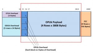
Figure 1, Illustration of the OPUk Frame – within the OTUk Frame.
In Figure 2, I take a closer look at the OPUk frame structure and show a more detailed drawing of the OPUk Overhead Bytes within the OPUk Frame.

Figure 2, Illustration of the OPUk Overhead Bytes – for AMP Applications
This figure shows five (5) Overhead Bytes that play a role in AMP.
- JC1 – Justification Control Byte # 1
- JC2 – Justification Control Byte # 2
- JC3 – Justification Control Byte # 3
- NJO – Negative Justification Opportunity Byte
- PJO – Positive Justification Opportunity Byte
Figure 2 also shows the bit format for the three Justification Control Bytes. This figure shows that Bits 1 through 6 (within each of these 3 bytes) are labeled RES (Reserved) and do not have a role in AMP.
This figure also shows Bits 7 and 8 (within these 3 bytes), which we have labeled JC7 and JC8, do have a role in AMP.
Has Inflation got You Down? Our Price Discounts Can Help You Fight Inflation and Become an Expert on OTN!!! Click on the Banner Below to Learn More!!!
Discount Available for a Short Time!!!

Justification Events within an OPU Frame
We earlier stated that if the System Designer wishes to use AMP to map a non-OTN client signal into an OPUk frame, then they must make sure that the frequency differences between the client signal and that for the OPUk payload are within ±65ppm.
Since there is no requirement to phase-lock the OPUk Payload frequency to the client signal frequency (as ITU-T G.709 requires for BMP applications), it is unlikely that these two signals will be at the same rate.
They will, most likely, be close (in frequency) to each other but off in one direction or the other.
In this case, the Source (OTN) Path Terminating Equipment (PTE) will generate many of its OPUk frames with no justification events. But, because these two signal frequencies will typically not be identical, the Source PTE will eventually generate OPUk frames with justification events. We sometimes call these justification events slip events in other forms of data communication.
NOTE: These justification events are also similar to the pointer justification events in SONET/SDH Networks.
The Source PTE will use these Justification Events to compensate for the frequency differences between the Client and the server signal.
Please see the post on “slip events” to understand the mechanics of slip events (e.g., why they occur and how we can elegantly handle them).
A Source PTE can generate three (3) types of OPUk frames in AMP.
- OPUk frames with NO Justification Events (e.g., The Nominal Condition)
- OPUk frames with Negative-Justification events (occurs periodically if the Client Bit Rate > OPUk Bit Rate)
- OPUk frames with Positive-Justification events (appears regularly, if the Client Bit Rate < OPUk Bit Rate)
We will discuss each of these types of OPUk frames below.
The Normal Situation – The Source PTE creates an OPUk Frame with No Justification Activities.
Many of the OPUk frames that a Source PTE generates will belong to this category for AMP applications.
Figure 3 shows a drawing of an OPUk Frame, with NO Justification events occurring.

Figure 3, An Illustration of an OPUk Frame with NO Justification events occurring
This figure shows that this OPUk frame does NOT have a Justification Event by:
- Setting at least two (out of the three) sets of JC7 and JC8 bit-fields to [0, 0] as shown above.
- The PJO byte field is currently carrying a client data byte (as it usually does) – in this OPUk frame.
- The NJO byte field is NOT transporting a client data byte but is (instead) carrying a stuff byte (which is also a nominal condition).
The settings within the JC7 and JC8 bit-fields alert the Sink PTE (at the other end of the network) that there is no justification event occurring within this OPUk frame and:
- That the PJO byte-field is currently carrying client data, and
- The NJO byte field is transporting a stuff-byte (and is NOT transporting client data).
NOTE: If (by design or accident) the OPUk payload rate is equivalent to the Client bit-rate, then the Source PTE will ALWAYS generate these types of OPUk frames (e.g., with NO Justification Events).
If the System Designer has achieved this synchronous relationship (between the OPUk and the Client signal) by design, this becomes Bit-Synchronous Mapping (BMP).
Negative Stuff Event (Occurs if the Client Bit Rate > OPUk Bit Rate)
If the Client-data bit rate is slightly faster than that for the OPUk payload rate, then (with no intervention) the Mapper Buffer will eventually fill up.
AMP uses Negative-Stuffing (or Negative Justification) to prevent the Mapper buffer from Overflowing.
In this case, the Source PTE will (temporarily) increase our Server (OPUk) signal’s bandwidth (to pull additional data out of the Mapper Buffer) by forcing both the PJO and the NJO bytes to carry client data momentarily.
Hence, for systems in which the Client data bit rate is faster than the OPUk payload bit rate, the Source PTE will periodically need to generate OPUk frames with Negative Justification to keep the Mapper Buffer from filling up.
Figure 4 shows a drawing of such an OPUk frame.

Figure 4, Illustration of an OPUk Frame with Negative Justification occurring
This figure shows that this OPUk frame has a Negative Justification Event by setting at least two (of the three) sets of JC7 and JC8 bits to [0, 1], as I show above.
The Source PTE will also (for this particular OPUk frame) use both the NJO and the PJO byte fields to carry client data bytes.
When the Source PTE sets the JC7 and JC8 bit-fields to these values, it notifies the Sink PTE (at the remote end of the network) of the roles of the NJO and PJO bytes within this OPUk frame.
NOTES:
- For the NO Justification OPUk frames, the NJO byte is considered part of the OPUk Overhead and usually does not transport any client data. For Negative Justification OPUk frames, the NJO byte will (for this OPUk frame) be carrying client data.
- If the Client-data bit rate is faster than the OPUk Payload rate, then the PJO byte will ALWAYS carry client data (in every OPUk frame). In this case, we will sometimes use the NJO byte to transport client data (within OPUk frames with justification events).
Positive Stuff Event (Occurs if the Client Bit Rate < OPUk Bit Rate)
If the Client-data bit-rate is slightly slower than that for the OPUk Payload rate, then (with no intervention) the Mapper Buffer will eventually be depleted.
AMP uses Positive-Stuffing (or Positive Justification) to avoid depleting the Mapper buffer.
In this case, the Source PTE will temporarily reduce the Server signal’s (e.g., the OPUk signal) bandwidth (for this OPUk frame) by forcing both the PJO and the NJO bytes to transport stuff (and NOT client) data.
Hence, for designs in which the Client data bit rate is slower than the OPUk payload, the Source PTE will periodically generate OPUk frames with Positive Justification to avoid depleting the Mapper Buffer.
NOTE: For the NO Justification OPUk Frames, the PJO byte field will be carrying client data. But, during Positive Justification frames, the PJO byte will transport a stuff (or dummy) byte instead. In other words, the Positive Justification OPUk frame will not carry client data within the PJO byte-field.
This action momentarily slows the rate at which the Server pulls data out of the Mapper Buffer and keeps the buffer from depleting.
Figure 5 shows a drawing of an OPUk frame with Positive Justification occurring.

Figure 5, Illustration of an OPUk Frame with Positive Justification occurring
This figure shows that this OPUk frame has a Positive Justification event by setting at least two (of the three) sets of JC7 and JC8 bits to “[1, 1].
When the Source PTE sets the JC7 and JC8 bit-fields to these values, it notifies the Sink PTE (at the remote end of the network) of the roles of the NJO and PJO bytes within this OPUk frame.
NOTE: If the Client data rate is slower than the OPUk Payload rate, then the NJO byte will ALWAYS function as a stuff byte (e.g., never carrying client data), and the PJO will sometimes function as a stuff byte (during OPUk frames with justification events).
Interpreting the JC7 and JC8 Bits
Table 1 summarizes how to understand the JC7 and JC8 bits (within two out of the three Justification Bytes) and the corresponding roles for the NJO and PJO bytes within the OPUk Frame.
Table 1, How to Interpret the Settings of the JC7 and JC8 bits within Two (of the Three) Justification Bytes, and the corresponding roles for the NJO and PJO bytes within the OPU Frame – When Transporting a Non-OTN Client Signal

AMP and De-Mapping Jitter
AMP poses some challenges for the System Designer’s efforts to control de-mapping jitter to meet system requirements. BMP offers the best de-mapping jitter of the three recommended Mapping Procedures.
However, AMP imposes all of the following contributions (and challenges) to meeting de-mapping jitter requirements.
- The presence of OTUk/ODUk/OPUk overhead bytes within the OTN signal (this challenge exists for BMP as well)
- Fixed-byte stuffing – while mapping the client signal into the OPUk frame (this challenge exists for BMP as well)
- Justification Events, also known as variable-stuffing, are unique to AMP.
Each Justification Event imposes 8UI-pp of mapping-related jitter within the client signal.
The System Designer will need to implement some clock-smoothing or jitter attenuation scheme to comply with de-mapping jitter requirements.
If the System Designer is transporting SONET/SDH data (which has very stringent jitter requirements) through the OTN, we recommend using BMP instead of AMP. Otherwise, the designer will have to implement some very robust jitter attenuation solutions (at the Sink PTE) when de-mapping this client signal from the OPUk frame.
ITU-T G.709 Recommendations on Using AMP
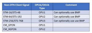
Table 2 presents a list of the Non-OTN Client signals that ITU-T G.709 recommends using AMP when mapping these signals into each OPUk/ODUk Structures.
Table 2, List of Client Signals that ITU-T G.709 Recommends using AMP when mapping into an OPUk Structure
Can we use AMP for all OPUk rates?
We can use AMP for the OPU1, OPU2, and OPU3 server signals. However, we cannot use AMP for mapping client signals into an OPU0 or OPU4 server signal.
ITU-T G.709 recommends using GMP to map client signals into OPU0 and OPU4 signals.
Summary
Table 3 summarizes the timing requirements (between the Client Clock Signal and that for the OPUk/ODUk clock) that the System Designer must follow before using any ITU-T G.709 Recommended Mapping Procedures. Please note that I have highlighted the AMP items (within Table 3) with a “Red Rectangular” outline.
Table 3, Mapping Procedure Timing Requirements

Has Inflation got You Down? Our Price Discounts Can Help You Fight Inflation and Help You Become an Expert on OTN!! Click on the Banner Below to Learn More!!!
Discounts Available for a Short Time!!!

For More Information on OTN Posts in this Blog, click on the Image below.
