

What is the OTUk-BEI (Backward Error Indicator) or SM-BEI Parameter?
The purpose of this post is to define the SM-BEI (Section Monitor – Backward Error Indicator) parameter that a Source STE will generate, and a Sink STE will tally at the OTUk-Layer.
Introduction
In another post, we describe how the Sink STE (OTUk_TT_Sk function) will compute and verify the SM-BIP-8 value within each incoming OTUk frame.
NOTE: I will use the terms Sink STE and OTUk_TT_Sk function interchangeably throughout this post.
The Sink STE performs this task to check for any occurrences of bit errors during data transmission (over optical fiber) from the STE Source Terminal to the STE Sink Terminal.
However, just as the Sink STE (through its near-end Source STE) sends the SM-BDI indicator back out to the remote Terminal whenever it declares a service-affecting defect. The Sink STE (again, through its near-end Source STE) will also send out information to the remote Terminal to reflect the number of BIP-8 errors detected within each incoming OTUk frame.
We call this information the Backward-Error Indicator (or BEI). I will explain how we generate and transport this parameter below.
A High-Level Overview of the SM-BEI Parameter and How we Use it.
Before we get into the details of how things work with the various Atomic Functions and Ports, let’s spend some time discussing the underlying philosophy for transmitting the SM-BEI indicator.
Let us consider two Network Elements. We will call one Network Element, N.E East, and the other Network Element N.E. West. We have connected these two networks via a Bidirectional Optical Connection, as shown below in Figure 1.

Figure 1, Illustration of Network Elements East and West connected over a Bidirectional Fiber Optic Connection.
Now let’s consider two possible cases when dealing with SM-BIP-8 errors and SM-BEI.
- The Unerred Case (where the Number of BIP-8 Errors = 0) and
- The Erred Case (where the Number of BIP-8 Errors = 5)
The Unerred Case (where the Number of BIP-8 Errors = 0)
Let’s assume that the OTUk Transceiver and OTUk Framer (within Network Element EAST) are not detecting any BIP-8 errors within a given OTUk frame.
We show this case below in Figure 2.

Figure 2, Illustration of Network Element EAST detecting NO BIP-8 Errors within OTUk frame # n
Please note that in Figure 2, I show that both the OTUk Transceiver and OTUk Framer blocks (within Network Element EAST) are detecting ZERO BIP-8 errors. I show this because many OTUk Transceivers will also include some OTUk Framing capability and can detect and flag BIP-8 errors.
In this case, Network Element EAST will respond to this ZERO BIP-8 Error condition by setting the BEI field (within its next outbound OTUk frame – back to Network Element WEST) to “0x00”.
Why “0000”?
Because that’s the Number of BIP-8 Errors that the OTUk Transceivers/Framer blocks have detected in their most recently received OTU frames.
Figure 3 shows Network Element EAST setting the BEI field to 0x00 within its next outbound OTUk frame.

Figure 3, Illustration of Network Element EAST responding to the NO BIP-8 Error Condition by setting BEI = 0 within its next outbound OTUk frame.
Both the OTUk Transceiver and Framer (within Network Element WEST) will receive this OTUk frame (with BEI = 0), and it will “know” the quality of its OTUk signal (out to Network Element EAST) is GOOD.
Therefore, the BEI field (within the OTUk Overhead) gives a Network Element a way to provide feedback to an upstream Network Element about the quality of its output signal.
As long as Network Element WEST receives OTUk frames with the BEI field set to 0, it has some indication that it is transmitting a good quality OTUk signal out to Network Element EAST.
NOTE: Since this is a bidirectional connection between Network Elements EAST and WEST, then Network Element WEST can (and will) provide the same type of feedback to Network Element EAST.
Now let’s move on to the Erred Case.
The Erred Case (where the Number of BIP-8 Errors = 5)
Now that we have covered the No-Error condition let’s cover a different situation. Let us assume that Network Element EAST has just received an OTUk frame, which detects 5 BIP-8 errors.
I show an illustration of this condition below in Figure 4.

Figure 4, Illustration of Network Element EAST detecting 5 BIP-8 Errors within OTUk Frame # n
In this case, Network Element EAST will respond to this error condition by setting the BEI field (within its very next outbound OTUk frame – back out to Network Element WEST) to “0x05” (e.g., the same number of BIP-8 errors that it detected) within its recently received OTUk frame.
Why “0x05”?
Because that’s the number of BIP-8 bit errors that Network Element EAST has detected within its most recently received OTUk frame.
Figure 5 shows Network Element EAST setting the BEI field to 0x05 within its next OTUk frame.

Figure 5, Illustration of Network Element EAST responding to the 5 BIP-8 Error Condition by setting BEI = 5 within its next outbound OTUk frame
In this case, since Network Element EAST sets the BEI-field to “0x05”, it is giving Network Element WEST some feedback that it (Network Element EAST) is having problems with the OTUk data-stream that it is receiving from Network Element WEST.
Now that we understand the underlying philosophy behind using the SM-BEI fields, let’s discuss the SM-BEI parameter in greater detail.
New Comprehensive OTN Training…Available Now. Click on the Banner Below to Learn More!!
Discounts Available for a Short Time!!!

An In-depth Discussion – How Does the Sink STE generate the BEI Parameter?
In the SM-BIP-8 Post, I mentioned that the Sink STE would locally compute its version of the SM-BIP-8 value based upon the contents within the OPUk portion of the OTUk frame that it has received.
I also mentioned that this SM-BIP-8 value is an 8-bit value.
The Sink STE (or OTUk_TT_Sk function) will then read out the contents of the SM-BIP-8 byte two OTUk frame periods later, and it will compare these two BIP-8 values.
I show the location of the BIP-8 Value, with respect to the OTUk Frame (that we used to compute this value), below in Figure 6.

Figure 6, The Location of the BIP-8 Value, with respect to the OTUk Frame (that we used to compute this value)
Comparing the Locally Computed BIP-8 Value with the Remotely Computed Value
At this point, the Sink PTE will compare its locally-computed SM-BIP-8 value with the remotely-computed SM-BIP-8 value (read out from the SM-BIP-8 byte field – two OTUk frame periods later).
If these byte values (of BIP-8 values) are equal, then we can state that this OTUk frame incurred no bit errors during transmission over the optical fiber.
On the other hand, if these two BIP-8 values are NOT the same, then the Sink STE (or OTUk_TT_Sk function) notes how many bits (between these two BIP-8 values) must be different from each other.
In other words, as the OTUk_TT_Sk function compares its locally computed BIP-8 value and that which it reads in from the BIP-8 byte-field within the incoming OTUk data stream. It will do this by performing a bit-by-bit XOR operation with each of these byte values.
The OTUk_TT_Sk function must then count the numbers of “1s” that occur during this bitwise XOR comparison. The OTUk_TT_Sk function will come up with any of the following nine (9) possible results.
- 0 bits in Error – Error-Free Transmission
- 1 bit in Error
- 2 bits in Error
- 3 bits in Error
- 4 bits in Error
- 5 bits in Error
- 6 bits in Error
- 7 bits in Error
- 8 (all) bits in Error
In Figure 7, I show a draw of a Bit-Wise XOR Comparator that the OTUk_TT_Sk function can use to compare its locally-computed BIP-8 value with the remotely-computed BIP-8 value.

The OTUk_TT_Sk function will need to send these BIP-8 comparison results back out to the remote terminal (the source of the OTUk signal that we are monitoring) in the form of BEI (Backward-Error-Indicator) value.
How does the OTUk_TT_Sk send out SM-BEI Information to the Remote Terminal?
Once the OTUk_TT_Sk function has performed the comparison (between its locally computed BIP-8 value with the remote-computed value), it then needs to report this information back to the remote terminal.
The OTUk_TT_Sk function will send a command to its collocated OTUk_TT_So function via the BEI (or RI_BEI) port.
I show a drawing of the OTUk_TT_Sk function, its collocated OTUk_TT_So function,
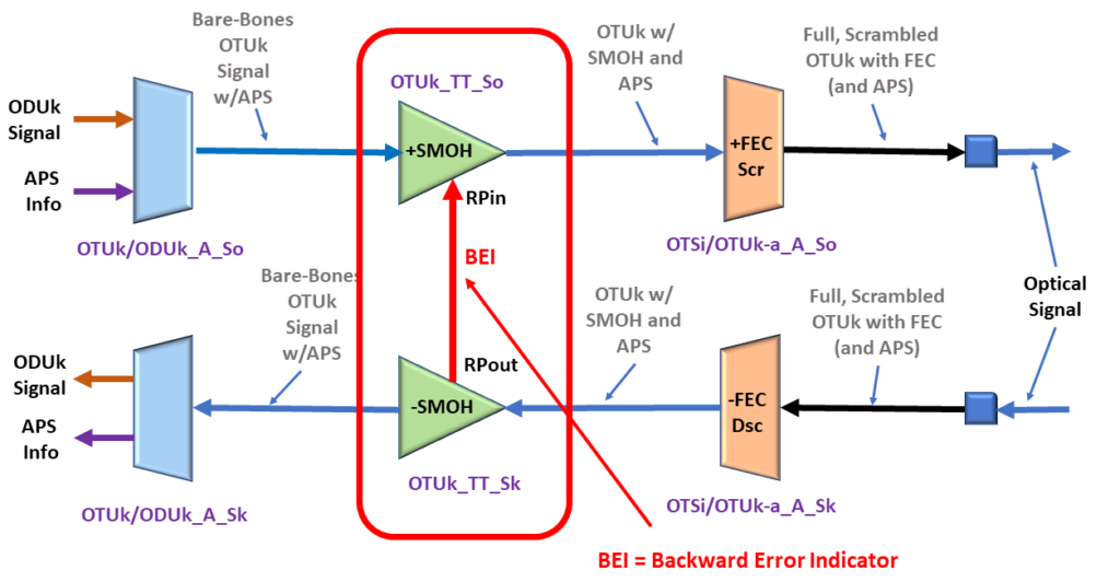
Figure 8, Illustration of the OTUk_TT_Sk, its collocated OTUk_TT_So function, and the BEI port.
The OTUk_TT_Sk function will use the BEI port to tell the OTUk_TT_So function what value it should set the BEI/BIAE nibble field to during its next outbound OTUk frame.
How does the OTUk Network Element transmit the SM-BEI Indicator?
The Network Element will transmit the SM-BEI indicator by setting the BEI/BIAE nibble-field within the SM (Section Monitoring) byte, to the BEI value, within each outbound OTUk frame.
The SM byte resides within the 3-byte SM (Section Monitoring) field of the OTUk Overhead.
Figures 9a, 9b, and 9c present the BEI/BIAE nibble-field location within an OTUk frame. First, Figure 9a shows the location of the SM field within the OTUk Overhead.

Figure 9a, The SM Field within the OTUk Overhead
Second, Figure 9b shows the location of the SM byte within the 3-byte SM Field.
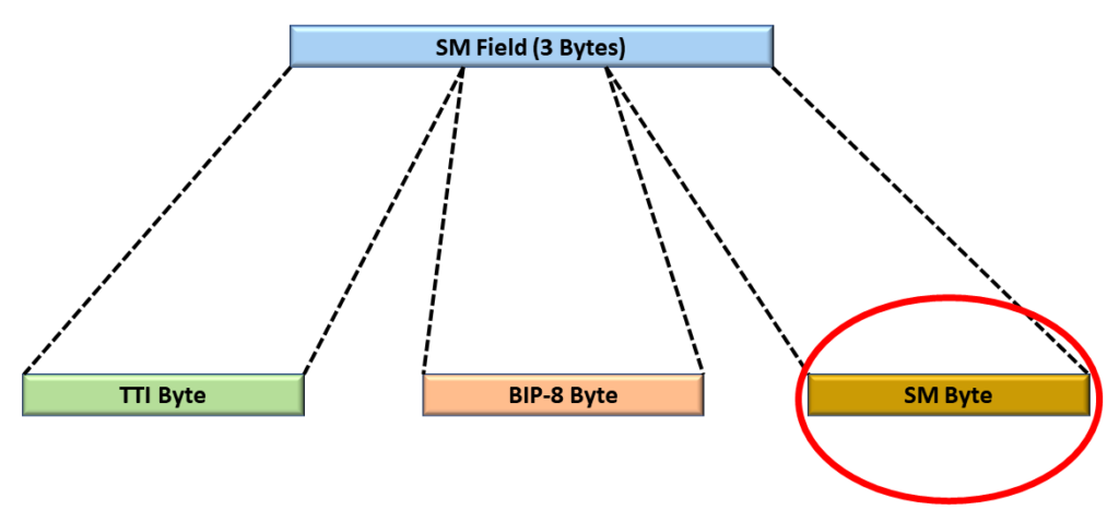
Figure 9b, The Location of the SM-Byte within the SM Field
Finally, Figure 9c presents the BEI/BIAE nibble-field location within the SM-byte.

Figure 9c, The Location of the BEI/BIAE nibble-field within the SM Byte, within the SM Field, of the OTUk Overhead.
What is the Official Interpretation of the SM-BEI/BIAE Nibble within the OTUk Frame?
The SM-BEI/BIAE Nibble does not just carry Backward Error Indication information. It also transports the BIAE (Backward Input Alignment Error Indicator).
Table 1 presents a list that defines how we should interpret each value for the SM-BEI/BIAE Nibble.
| SM-BEI/BIAE[1:4] Nibble Value | Is OTUk_TT_Sk Declaring dIAE? | BEI Count (Value) if any |
|---|---|---|
| 0000 | NO | 0 |
| 0001 | NO | 1 |
| 0010 | NO | 2 |
| 0011 | NO | 3 |
| 0100 | NO | 4 |
| 0101 | NO | 5 |
| 0110 | NO | 6 |
| 0111 | NO | 7 |
| 1000 | NO | 8 |
| 1001, 1010 | NO | 0 |
| 1011 | YES (BIAE Indicator) | 0 |
| 1100 through 1111 | NO | 0 |
This table shows that only nibble values of 0x01 through 0x08 reflect some (non-zero) Backward Error Indication count.
Summary
Each Network Element can use the BEI/BIAE Nibble-field within the SM byte to provide the remote Network Element with feedback on the number of SM-BIP-8 bit errors they are detecting.
The remote Network Element will note (and increment the pF_EBC parameter) each time it receives an OTUk frame, in which the SM-BEI/BIAE nibble-field ranges between 1 and 8.
In another post, I discuss the pF_EBC (Far-End – Error Block Count) parameter in greater detail.
Clueless about OTN? We Can Help!! Click on the Banner Below to Learn More!!
Discounts Available for a Short Time!!!

For More Information on OTN Posts in this Blog, click on the Image below.
