What is the Wait-to-Restore Period?

This post briefly defines and describes the term Wait-to-Restore for Protection-Switching systems.


What is the Wait-to-Restore Period within a Protection-Switching System?

The purpose of this post is to describe and define the Wait-to-Restore period within a Revertive Protection-Switching system.

Introduction

All Protection Groups will perform Protection-Switching, to route the Normal Traffic Signal around a defective Working Transport entity anytime it is declaring a service-affecting or signal degrade (dDEG) defect with that Working Transport entity.

In other words, the Protection Group will route the Normal Traffic Signal through the Protection Transport entity for the duration it declares this defect condition.

Whenever a Revertive Protection Group clears that defect, it will switch the Normal Traffic Signal back to flowing through the Working Transport entity.

We call this second switching procedure (to return the Protection-Group to its NORMAL, pre-protection-switching state) revertive switching.

In contrast, a Non-Revertive Protection Group will NOT perform this revertive switch, and the Normal Traffic Signal will continue to flow through the Protection Transport entity indefinitely.

When the Tail-End Node clears the Service-Affecting Defect

Protection-Switching events are very disruptive to the Normal Traffic Signal.  Each time we perform a protection-switching procedure, we induce a glitch (or a burst of bit errors) and signal discontinuity within the Normal Traffic Signal.

Therefore, Protection-Switching events should not be a common occurrence within any network.

To minimize the number of protection-switching events (occurring within a network), the Protection-Group will usually force the Tail-End Node to go through a Wait-to-Restore period after it clears the service-affecting or dDEG defect (which caused the Protection-Switching event in the first place) before it can proceed on to the next step and revert the protection-switching (and traffic).

In other words, the Tail-End Node (within a Protection-Group) will execute the following steps each time it clears a defect, which causes a protection-switching event.

  1. It clears the defect condition.
  2. The Tail-End circuit will then start a Wait-to-Restore Timer and will wait until this timer expires before it proceeds to the next step.
  3. If the Tail-End circuit declares another service-affecting defect while waiting for this Wait-to-Restore timer to expire, it will reset this timer back to zero and continue waiting.
  4. Once the Wait-to-Restore timer expires, the Tail-End circuit will revert the protection-switched configuration into the NORMAL configuration.  In other words, the Normal Traffic Signal will (once again) travel along the Working Transport entity.  

I show these same steps within the Revertive Procedure Flow Chart below.

Revertive Protection Switching Procedure Flow Chart

Figure 1, Flow-Chart of the Revertive Protection-Switching Procedure – after the Service-Affecting defect clears.

What is the purpose of using this Wait-to-Restore Period?

There are two main reasons why we use the Wait-to-Restore period in a Protection-Switching system.

  1. To make sure that the condition of the Working Transport entity has stabilized and is not still declaring intermittent defects before we start to pass the Normal Traffic signal through it again.
  2. And to reduce the number of protection-switching events within a protection group.

How Long Should the Wait-to-Restore period be?

ITU-T G.808.1 recommends that this period be between 5 and 12 minutes.

In Summary

All revertive protection-switching systems must wait through a Wait-to-Restore period (after clearing the defect condition) before executing the revertive switch.

The purpose of waiting through this Wait-to-Restore period is to prevent multiple Protection-Switching events due to intermittent defects within the Working Transport entity.

ITU-T G.808.1 recommends that this Wait-to-Restore period be between 5 and 12 minutes.

This means that the Tail-End circuit must go through this Wait-to-Restore period and declare no defects for the entire 5 to 12-minute period before it can move on to revert its protection-switching.

Has Inflation got You Down? Our Price Discounts Can Help You Beat Inflation and Become an Expert on OTN!! Click on the Banner Below to Learn More!!

Discounts Available for a Short Time!!!

For More Information on other Protection-Switching-related Posts, Click on the Image Below.

Protection-Switching Related Blog

Protection-Switching Related Blog Posts

Protection-Switching Related Blog Posts Basic Protection-Switching Terms Head-End (Source Node) Hold-Off Timer Protection-Group Protection-Transport entity Selector Switch Tail-End (Sink Node) ...

What is a Revertive APS System?

This post briefly defines and describes Revertive Protection Switching.

What is a Revertive APS (Automatic Protection-Switching) System?

If an Automatic Protection System is Revertive, then that means that the system will always return to transmitting/accepting the Normal Traffic Signal through the Working Transport Entity anytime the system has recovered from a defect or an external request (for Protection Switching).

An Example of Revertive Switching

Let’s use an example to help define the term revertive.

The Normal/No Defect Case

Let’s consider a 1:2 Protection Switching System shown below in Figure 1.

Linear Protection Switching - 1:2 Protection-Switching Architecture

Figure 1, Illustration of a 1:2 Protection Switching System – West to East Direction

NOTE:  Because the 1:N Protection-Switching pictures are somewhat complicated, I only show the West-to-East Direction of this Protection-Switching system to keep these figures simple.

In Figure 1, all is well.  Both of the Normal Traffic Signals within the figure (e.g., Normal Traffic Signal # 1 and Normal Traffic Signal # 2) flow from their Head-End Nodes to their Tail-End Nodes with no defects or impairments.

The Defect Case

Let’s assume that an impairment occurs within Working Transport Entity # 1 and that the Tail-End circuitry (associated with Working Transport Entity # 1) declares either a Service-Affecting or Signal Degrade Defect (e.g., declares the SF or SD condition).

We show this scenario below in Figure 2.

1:2 Protection Switching Scheme - Defect in Working Transport entity # 1

Figure 2, Illustration of our 1:2 Protection-Switching system (West to East Direction only) with a Service-Affecting Defect occurring in Working Transport Entity # 1 

The Protection-Switch

Whenever the Tail-End circuitry (within Figure 2) declares the service-affecting defect condition, it will (after numerous steps) achieve the Protection-Switching configuration shown below in Figure 3.

1:2 Protection Switching Scheme - Protection Event

Figure 3, Illustration of our 1:2 Protection-Switching system (West to East Direction only) following Protection-Switching.

NOTE:  Check out the post on the APS Protocol (within “THE BEST DARN OTN TRAINING PERIOD” training sessions) to understand the sequence of steps that the Tail-End and the Head-End Nodes had to execute to achieve the configuration we show in Figure 3.

Our 1:2 Protection-Switching system will remain in the condition shown in Figure 3 for the duration that the Tail-End Circuitry declares this defect within Working Transport Entity # 1.

The Defect Clears

Eventually, the Service-Provider will roll trucks (e.g., send repair personnel out to fix the fault condition, causing the service-affecting defect); and the defect will clear.

Once this service-affecting defect clears, the East Network Element will wait some WTR (or Wait-to-Restore) period before it proceeds with the Revertive switch.

Clueless about OTN? We Can Help!!! Click on the Banner Below to Learn More!!!

Corporate Discounts Available!!

The Revertive-Switch

Once the WTR period expires (with no further defects occurring within Working Transport Entity # 1), our Protection Group will switch and route Normal Traffic Signal # 1 back through Working Transport Entity # 1.

We show the resulting configuration below in Figure 4.

Linear Protection Switching - 1:2 Protection-Switching Architecture

Figure 4, Illustration of our 1:2 Protection-Switching System (West to East Direction ONLY) following Revertive-Switch

The Overall Flow for Revertive Switching

Figure 5 presents a flow-chart diagram that summarizes the Revertive Protection-Switching Procedure.

Revertive Protection Switching Procedure Flow Chart

Figure 5, Flow-Chart Diagram summarizing the Revertive Protection Switching Procedure

Check out the relevant post for more information about the Wait-to-Restore period and Timer.

In Summary

A Revertive Protection-Switching system will always perform a second switching procedure after the defect has cleared.

This second switching procedure will return the Protection Group to the state of having the Normal Traffic Signal flowing through the Working Transport Entity.

A Non-Revertive Protection-Switching system will NOT perform this second switching after the Tail-End Node has cleared the service-affecting defect.

Therefore, in a Non-Revertive Protection-Switching system, the Normal Traffic Signal will continue to flow through the Protection Transport entity indefinitely.

To use a Revertive Protection-Switching System or NOT.

There are advantages and disadvantages to using a Revertive system.

I list some of these advantages and disadvantages below.

Disadvantages of Using a Revertive System

  • Each service-affecting or signal degrade defect (SD or SF) occurrence will result in two Switching Events.  We will disrupt the Normal Traffic Signal twice for each defect condition.
    • The first switching event is in response to the defect condition, and
    • The follow-up Revert Switching event.

We strongly advise that you use Revertive Protection-Switching if:

  • You are using a Shared-Ring Protection-Switching system.
  • If the Bandwidth or Performance Capability of the Protection Transport entity is lower or worse than that for the Working Transport Entity (e.g., has more bit errors, inferior performance)
  • Whenever there is a much more significant delay in the Protection Transport entity (than that for the Working Transport entity)
  • If one needs to track which Protected ports are using the Working Transport entity and which are using the Protection Transport entities
  • Protection Transport entity must be readily available for multiple other Working Transport entities (as in a 1:N Protection Architecture).

Has Inflation got You Down? Our Price Discounts Can Help You Beat Inflation and Help You to Become an Expert on OTN!! Click on the Banner Below to Learn More!!!

Discounts Available for a Short Time!!!

Click on the Image Below to see more Protection-Switching related content on this Blog:

Protection-Switching Related Blog

Protection-Switching Related Blog Posts

Protection-Switching Related Blog Posts Basic Protection-Switching Terms Head-End (Source Node) Hold-Off Timer Protection-Group Protection-Transport entity Selector Switch Tail-End (Sink Node) ...

Shared-Ring Protection Switching

This post briefly defines the term: Shared-Ring Protection-Switching


What is Shared-Ring Protection Switching?

A Shared-Ring Protection Switching system is a Protection System that contains at least three (3) Nodes.

Each Node within this Shared-Ring Protection-Switching System (or Ring) is connected to two neighboring nodes.

I show an illustration of a Shared-Ring Protection-Switching System below in Figure 1.

4-Fibre/4-Lambda Shared-Ring Protection-Switching System

Figure 1, Illustration of a Shared-Ring Protection-Switching System

Figure 1 presents a shared-ring protection-switching system that consists of six (6) nodes that are each connected to a shared ring that contains four (4) Optical loops (or rings).

Some optical rings carry traffic that flows in the clockwise direction (through each node).  Other rings carry traffic that flows in the counter-clockwise direction.

In Figure 1, I have labeled some of these optical loops as “Working” or Working Transport Entity loops and others as “Protect” or Protection Transport Entity loops.

What are the Nodes within a Shared-Ring Protection-Switching System?

Each node (on the Shared-Ring Protection-Switching system) is an electrical/optical system that functions similarly to an Add-Drop-MUX.

Some data traveling on an optical loop (within the ring) will pass through these nodes.  These Nodes also can add in and drop-out some of the data traveling on these loops.

I show the Add-, Drop- and Pass-Through capability of these Nodes below in Figure 2.

Add-Drop MUX features of Nodes in Shared-Ring Protection-Switching

Figure 2, Illustration of the Add-, Drop- and Pass-Through capabilities of a given node, sitting on the shared-ring.  

It is also important to note that each Node can function as either a Source (or Head-End) Node, a Sink (or Tail-End) Node, or both.

Types of Shared-Ring Protection-Switching Systems

ITU-T G.873.2 defines the following two types of Shared-Ring Protection-Switching systems.

  • The 2-Fibre/2-Lambda Shared-Ring Protection-Switching system, and
  • The 4-Fibre/4-Lambda Shared-Ring Protection-Switching system.

Please click on the links above to learn more about these Shared-Ring Protection-Switching systems.

Types of Protection-Switching within a Shared-Ring Protection-Switching System

The Shared-Ring Protection-Switching system can support both the following kinds of Protection-Switching.

Click on the above links to learn more about these types of Protection-Switching within a Shared-Ring Protection-Switching system.

Design Variations for Shared-Ring Protection-Switching Systems

Shared-Ring Protection-Switching systems are available in a wide variety of features.  I’ve listed some of these features and their possible variations below.

Shared-Ring Protection-Switching Types

  • 2-Fibre/2-Lambda Shared-Ring Protection-Switching systems
  • 4-Fibre/4-Lambda Shared-Ring Protection-Switching systems.

Architecture Type

All Shared-Ring Protection-Switching is of the 1:N Protection-Switching Architecture.

Switching Type

All Shared-Ring Protection-Switching is Bidirectional.

Operation Type

All Shared-Ring Protection-Switching systems use Revertive Operation.

APS Protocol – Using the APS/PCC Channel

All Shared-Ring Protection-Switching systems use the APS Protocol.

What about other types of Protection-Switching?

Other types of Protection-Switching Systems are not Shared-Ring, such as Linear or Shared-Mesh Protection-Switching.

Has Inflation got You Down? Our Price Discounts Can Help You Beat Inflation and Become an Expert on OTN!! Click on the Banner Below to Learn More!!

Discounts Available for a Short Time!!!

Please Click on the Image below to See More Protection-Switching posts within this Blog.

OTN Related Blog

OTN Related Topics within this Blog

OTN Related Topics within this Blog General Topics Consequent Equations - What are they and How can you use them? ...

Linear Protection Switching

This post briefly defines the term: Linear Protection Switching. It also briefly defines 1+1, 1:N Protection Architectures.


What is Linear Protection Switching?

A Linear Protection-Switching System is a Protection System (or Protection Group) that contains two nodes:

Each of these two nodes is exchanging normal traffic signals, with each other, over a protected network that consists of both the Working Transport entity and the Protect Transport entity.

I show some simple pictures of Linear Protection Switching Systems below in Figures 1, 2, and 3.

The 1+1 Protection-Switching Architecture

1+1 Linear Protection-Switching System

Figure 1, Illustration of a Linear Protection Switching System (A 1+1 Protection-Switching System)

In Figure 1, I show a simple illustration of a 1+1 Protection-Switching system, which also presents the bidirectional traffic flow between the Head-End and Tail-End Nodes.

If you want to learn more about the 1+1 Protection-Switching Architecture, check out the post on this topic.

The 1:N Protection-Switching Architecture

Linear Protection Switching - 1:2 Protection Switching Architecture

Figure 2, Illustration of a Linear Protection Switching System (A 1:2 Protection-Switching System) – for the East to West Direction

Linear Protection Switching - 1:2 Protection-Switching Architecture

Figure 3, Illustration of a Linear Protection Switching System (A 1:2 Protection-Switching System) – for the West to East Direction

Figures 2 and 3 each present an illustration of a 1:2 (or 1:N) Protection-Switching System.

Please note that the 1:N Protection-Switching Architecture figures are more complicated than that for the 1+1 Protection-Switching Architecture.

Therefore, I needed to show this architecture in the form of two figures. 

One figure shows the traffic flowing from West to East, and the other illustrates the traffic flowing from East to West.

If you want to learn more about the 1:2 (or 1:N) Protection-Switching architecture, check out the post on that topic.

In summary, the 1+1 and the 1:N Protection-Switching schemes are Linear-Protection Protection-Switching systems.

Design Variations for Linear Protection-Switching Systems

Linear  Protection-Switching systems are available in a wide variety of features.  I’ve listed some of these features and their variations below.

Architecture

Switching Type

Operation Type

APS Protocol – Using the APS/PCC Channel

Click on any of the links above to learn more about these design variations within a Linear Protection-Switching System.

What about Other Protection-Switching Architectures?

There are other types of Protection Switching systems, which are not Linear, such as Shared-Ring Protection-Switching or Shared-Mesh Protection-Switching.

Please see the relevant posts for more information about those types of Protection-Switching Systems.

Has Inflation got You Down? Our Price Discounts Can Help You Beat Inflation and Help You to Become An Expert on OTN!!! Click on the Banner Below to Learn More!!!

Discount Available for a Short Time!!

Click on the Image Below to see more Protection-Switching related content on this Blog:

Protection-Switching Related Blog

Protection-Switching Related Blog Posts

Protection-Switching Related Blog Posts Basic Protection-Switching Terms Head-End (Source Node) Hold-Off Timer Protection-Group Protection-Transport entity Selector Switch Tail-End (Sink Node) ...

What is 1:N Protection Switching?

This post defines and describes the 1:n Protection Switching architecture.

What is the 1:n Protection Switching Architecture?

ITU-T G.808 defines the “1:n (protection) architecture (n >= 1) as:

A 1:n protection architecture has n normal traffic signals, n working transport entities, and one protection transport entity.  

It may have an extra traffic signal.  

At the source end, a normal traffic signal is either permanently connected to its working transport entity and may be connected to the protection transport entity (in the case of a broadcast bridge) or is connected to either its working or protection transport entity (in the case of a selector bridge).  

The sink-end can select the normal traffic signal from either the working or the protection transport entity.  

An unprotected extra traffic signal can be transported via the protection transport entity whenever the protection transport entity is not used to carry a normal traffic signal.

What Does All This Mean?

As for all Protection Groups, a 1:n Protection Architecture consists of the following elements:

  • n instances of the Head-End (or Source-End)
  • n instances of the Tail-End (or Sink-End)
  • and n separate Normal Traffic Signals
  • n sets of Working Transport entities
  • a single Protect Transport entity
  • a single Extra Traffic Signal
  • Protection Switching Controller (that can detect and declare defects within the Normal Traffic Signals).
  • An APS Communications Link/Protocol (Required)

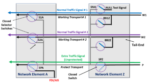
Figure 1 shows a variation of the 1:n Protection Switching architecture.

In this case, we show a 1:2 Protection Switching Architecture.

Basic Drawing of a 1:2 Protection Switching Scheme

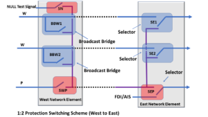
Figure 1, Illustration of a 1:2 Protection Switching Architecture

This figure shows that a Broadcast Bridge realizes each of the two Head-Ends (of this Protection Group).  We realize each of the two Tail-ends by a Selector Switch.

I have designated the Broadcast Bridges with the Blue Overlay Shading in this figure.

Likewise, I have designated the Selector Switches with the Red Overlay shading.

NOTES:  

  1. The user can also opt to realize the Head-ends with a Selector Switch for the 1:n Protection Switching Architecture.
  2. Figure 1 includes some other bells and whistles (in the form of some additional Selector Switches) that I will discuss later in this blog.

Clueless about OTN and Protection Switching? We Can Help!!! Click on the Banner Below to Learn More!!

Corporate Discounts Available!!!

How does the 1:n Protection Switching Architecture Work?

One of the noteworthy features of a 1:n Protection Switching Architecture is that you have a single Protection Transport entity that protects n Normal Traffic Signals.

This means that for the 1:n Protection Switching Architecture, you only need 1/n more bandwidth to transport the n Normal Traffic Signals in a protected manner, from the Head-ends to the Tail-ends (where n is the total number of Normal Traffic Signals that you are transporting via this Protection Group).

In contrast, for a 1+1 Protection Switching Architecture, you have one Protection Transport entity protecting one Normal Traffic Signal.

This means that we are providing the Normal Traffic Signal with twice the bandwidth required to transport this signal from the Head-End to the Tail-End in a protected manner.

For many applications, this is inefficient, expensive, and inconvenient.

Of course, this same ratio would also hold if you used a 1:1 Protection Switching Architecture.

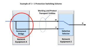
Another Key Characteristic of a 1:N Protection Architecture

Another critical characteristic of a 1:N Protection Architecture is the use of Broadcast Bridges on the Head-End Circuitry.  In contrast to a Permanent Bridge, during No-Defect Operation, there will not be a hardwired connection between the Normal Traffic Signal and the Working and Protection Transport entities.  There is only the connection between the Normal Traffic Signal and the Working Transport Entity.  When we are required to perform Protection-Switching, we will close the Broadcast Bridges and complete the electrical connection between the Normal Traffic Signal and the Protection Transport entity.  

We will discuss how the 1:n Protection Switching Architecture works by examining the following cases/conditions.

  • The Normal (No Defect) Case
  • A service-affect defect occurring Working Transport entity # 1
  • Protection Switching (after the defect has been declared).
  • The Normal (No Defect) Case – also using the Extra Traffic Signal

The Normal (No Defect) Case

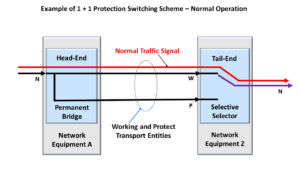
Figure 2 shows a drawing of the Normal (No Defect) Case.

In this case, we have two Network Elements that are exchanging data with each other.

One Network Element (which we labeled Network Element West) is transmitting data to another Network Element (which we labeled Network Element East).

In most actual applications, we would also have traffic going in the opposite direction (East to West).

But, to keep these figures simple, we are only showing one direction of traffic in each of the figures in this post.

In Figure 2, Normal Traffic Signal # 1 travels over Working Transport entity # 1.

Likewise, Normal Traffic Signal # 2 travels over Working Transport entity # 2.

Additionally, the Extra Traffic Signal is traveling over the Protection Transport entity.

There are no impairments on any of the Working Transport entities, and everything is expected in this case.

1:2 Protection Switching Scheme - Normal Condition - Extra Traffic Signal

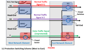
Figure 2, Illustration of the Normal (No Defect) Case 

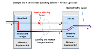
A Service-Affecting Defect occurs in Working Transport entity # 1

Now, let us assume that an impairment occurs in Working Transport entity # 1, such that some circuitry (sitting within the Tail-End of this Working Transport entity, within Network Element East) is declaring either a service-affecting defect such as SF (Signal Fail) or the signal degrade defect, such as SD (Signal Degrade).

In this case, Normal Traffic Signal # 1 can no longer travel on the Working Transport entity # 1.

Figure 3 shows a drawing of this condition.

1:2 Protection Switching Scheme - Defect in Working Transport entity # 1

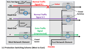
Figure 3, Illustration of a Service-Affecting Defect Occurring in Working Transport Entity # 1

Protection Switching – After the Defect (in Working Transport Entity # 1) has been declared

Now, since the Tail-End circuitry of Working Transport entity # 1, within Network Element East) has declared this defect condition, it needs to invoke Protection Switching.

In particular, this circuitry needs to perform the following four tasks.

  1. The circuitry within Network Element East needs to switch the local Selector Switch, which I’ve labeled SE1 (at the Tail-End of Working Transport entity # 1), away from this (now failed) Working Transport entity over to selecting the Protection Transport entity.
  2. The Network Element East circuitry also needs to send a command across the Transport entities back to the upstream Network Element (e.g., Network Element West).  In this case, Network Element East will also command Network Element West to invoke Protection Switching (for Working Transport entity # 1).
  3. Next, Network Element West (after it has received this command from Network Element East) then needs to command the Broadcast Switch, which I’ve labeled BBW1 (at the Head-end of Working Transport Entity # 1) to switch such that Normal Traffic Signal # 1 is now also connected to the Protection Transport entity.
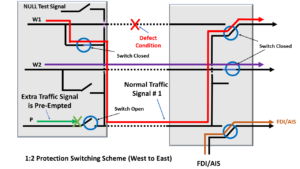
  4. Finally, Network Element West needs to pre-empt the Extra Traffic signal by opening the switch that I’ve labeled SWP.  Once this switch is OPEN, the Extra Traffic signal will no longer travel across the Protection Transport entity.

In this case, Normal Traffic Signal # 1 will now travel (from Network Element West to Network Element East) using the Protect Transport entity.

Figure 4 presents the resulting configuration (with Network Elements East and West) after protection switching.

1:2 Protection Switching Scheme - Protection Event
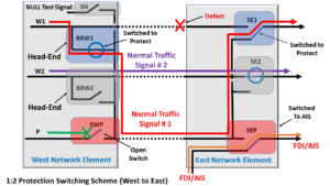
Figure 4, Illustration of our 1:2 Protection Switching Protect Group, following Protection Switching

NOTE:  Protection Groups using the 1:n Protection Switching scheme are required to support an APS Communications Channel to command and coordinate Protection Switching activities between the Head-ends and Tail-ends of the Protection Group.

This is how 1:N Protection Switching works.

Has Inflation got You Down? Our Price Discounts Can Help You Beat Inflation and Help You Become an Expert on OTN and Protection Switching!!! Click on the Banner to Learn More!!

Discounts Available for a Short Time!!

Additional Options in the 1:n Protection Switching Architecture

There are several options that users can use when designing a 1:n protection switching scheme.

Some of these options include:

  • Transmitting the NULL Signal during the Normal (No Defect) Case – as the Extra Traffic signal.
  • Transmitting the FDI/AIS signal during Protection Switching
  • Revertive Protection Switching
  • Unidirectional or Bidirectional protection switching

We will briefly discuss each of these options below.

Transmitting the NULL Signal during the Normal (No Defect) Case – as the Extra Traffic Signal.

In some cases, the user can transmit the NULL signal as the Extra Traffic signal (via the Protect Transport entities) anytime each of the n Working Transport entities is defect-free and is functioning properly.

In the Protection Group (discussed in this post), we could close the Switch labeled SN and open the Switch labeled SWP (within Network Element West).

This configuration setting would allow the NULL signal (that originates from Network Element West) to flow through the Protect Transport entity, as shown in Figure 5.

1:2 Protection Switching Sceme - Normal with NULL Signal

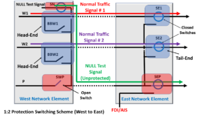
Figure 5, Transmitting the NULL Signal via the Protect Transport Entity, during Standby Times.  

Transmitting the FDI/AIS signal during Protection Switching

In many cases, the user will transmit the FDI/AIS signal towards the circuitry downstream from Network Element East by switching the switch, which I’ve labeled SEP (within Network Element East), away from the Protect Transport entity towards the FDI/AIS signal source.

Figure 4 (above) shows Network Element East transmitting the FDI/AIS indicator towards downstream traffic during Protection Switching.

The user would typically only do this whenever the Extra Traffic Signal (e.g., the NULL signal or some other low-priority signal) has been pre-empted due to a Protection Switching event.

The purpose of transmitting this FDI/AIS signal is to alert downstream equipment of a service-affecting defect condition within one of the Working Transport entities between Network Elements East and West.

NOTE:  For OTN applications, the Network Element will transmit the ODUk-AIS indicator during these protection switching events.

Revertive Protection Switching

Some Protection Groups will support Revertive operations, and others will not.

Suppose you designed a Protection Group to support Revertive operations.  In that case, the Protection Group will automatically reroute the affected Normal Traffic Signal back through its Working Transport entity shortly after the servicing-affecting defect (which caused the protection switching event in the first place) has cleared.

1:n Protection Switching systems typically support Revertive operations, whereas 1+1 Protection Switching systems may NOT support Revertive operations.

If a 1:n Protection Switching system was to support Revertive operations, then the Network Element that first declared (and is now clearing) the service-affecting defect; would have to send a command back to the other (remote) Network Element to coordinate revert protection switching activities (between both the Head-Ends and Tail-Ends of the Protection Group).

Please see the post on the Revertive Operation and the Automatic Protection Switching Channel for more details on this topic.

Unidirectional or Bidirectional Protection Switching

A 1:n Protection Switching scheme can support either Unidirectional or Bidirectional Protection Switching.

If the Protection Group supports Unidirectional Protection Switching, then the Network Element (that detects and declares the Service-Affecting defect within one of the Working Transport entities) will need to send the necessary command information (back to the upstream Network Element) to command and coordinate the Unidirectional Protection Switching event.

Conversely, suppose the Protection Group supports Bidirectional Protection Switching.  In that case, the Network Element (that detects and declares the Service-Affecting defect) will need to send the necessary command information (back to the upstream Network Element) to command and coordinate the Bidirectional Protection Switch.

Please see the posts for Unidirectional and Bidirectional Protection Switching for more details on this topic.

Has Inflation got You Down? Our Price Discounts Can Help You Beat Inflation and Help You Become an Expert on OTN!! Click on the Banner Below to Learn More!!!

Discounts Available for a Short Time!!

Click on the Image Below to see more Protection-Switching related content on this Blog:

Protection-Switching Related Blog

Protection-Switching Related Blog Posts

Protection-Switching Related Blog Posts Basic Protection-Switching Terms Head-End (Source Node) Hold-Off Timer Protection-Group Protection-Transport entity Selector Switch Tail-End (Sink Node) ...

What is the NULL Test Signal for OTN?

This post defines and describes the NULL Signal for OTN (Optical Transport Network) applications.

What is the NULL Test Signal for OTN?

What Exactly is the NULL Test Signal for OTN?

The NULL signal (for OTN) is an OPUk frame with all the following characteristics.

  • The PT (Payload Type) byte-field (within the PSI) is set to the value 0xFD (which indicates that this OPUk frame is transporting the NULL signal).
  • The rest of the 7 RES (Reserved) byte-fields (within the OPUk Overhead) are all set to an All-Zeros pattern (0x00).
  • All the payload bytes (within the OPUk frame) are set in an All-Zeros pattern.

Figure 1 shows a drawing of an OPUk Frame transporting the NULL signal.

OPUk_Frame transporting NULL Signal

Figure 1, An Illustration of the OPUk frame that is transporting the NULL signal

Any ODUk or OTUk frame that transports an OPUk frame with these characteristics carries the NULL signal.

Additionally, any of the following types of OPUk/ODUk signals can transport the NULL signal:

  • OPU0/ODU0
  • OPU1/ODU1
  • OPU2/ODU2
  • OPU2e/ODU2e
  • OPU3/ODU3
  • OPU4/ODU4
  • OPUflex/ODUflex

Clueless about OTN? We Can Help!! Click on the Banner Below to Learn More!!

Corporate Discounts Available!!!

Where and How would one use the NULL Signal?

ITU-T G.709 defines the NULL signal (for OTN) as a test signal.

Therefore, the System Architect can consider the NULL signal as a tool (in the toolbox) for testing and debugging features available to an OTN system.

Some system applications will transmit the NULL signal via the Protection Transport entity within a 1:1 or 1:n protection switching scheme.  In this case, the user will send the NULL signal instead of either the Extra-Traffic Signal or the ODUk-OCI Maintenance Signal.

Figure 2 shows a drawing of the 1:2 Protection Switching scheme, in which the user is transporting the NULL signal via the Protection Transport Entity.

1:2 Protection Switching scheme using the NULL Signal

Figure 2, An Illustration of a 1:2 Protection Switching scheme that is transporting the NULL signal via the Protection Transport entity

We can use the NULL signal in any application or situation whenever we need to continuously supply an optical signal (that is carrying timing information) to keep Clock Recovery PLL circuitry (within a downstream Network Element) locked onto the timing signal in the local Network Element.

Simultaneously, the NULL signal will indicate to the downstream Network Element that the connection is working correctly and that there are no defects upstream.

The NULL signal is unlike an AIS signal, which does indicate (to downstream Network Elements) the presence of service-affecting defect conditions upstream.

How Should a System Designer create the NULL Signal for OTN Applications?

The NULL signal (for OTN applications) consists of a fixed pattern.

Therefore, the user can generate OPUk signals (transporting the NULL signal) using a Pattern Generator, which gets its timing from a local clock oscillator.

The System Designer must also ensure that this NULL Signal generator function generates both the OTUk/ODUk Frame and Multi-Frame start indicators.

The Frame Start indicator (FS) should occur every 122,368 clock cycles (or ODUk frame period).

And the Multi-Frame Start indicator (MFS) should occur every 256 frames.

ITU-T G.798 specifies an adaptation function of the name ODUkP/NULL_A_So.

This function is responsible for generating an ODUk signal transporting the NULL signal.

This adaptation function generates the NULL signal from a free-running clock source, which then maps this signal into an OPUk/ODUk frame.

Finally, this function includes the OPUk overhead (e.g., the RES and PT fields) and a default ODUk overhead.

NOTE:  In the case of the default ODUk overhead, this function will set all the ODUk overhead fields to All-Zeros, except for the PM STAT field, which will be set to the value 001 (to indicate a Normal Path Signal).

Figure 3 illustrates the ODUkP/NULL_A_So function from ITU-T G.798.

ODUkP/NULL_A_So function block diagram

Figure 3 illustrates the ODUk/NULL_A_So function from ITU-T G.798.  

What are the Timing (Frequency Accuracy), Jitter, and Wander Requirements for the NULL Signal?

Please see the ODCa (ODU Clock for Asynchronous Mapping) post for the complete Frequency Accuracy and Jitter/Wander requirements of this NULL signal.

Summary

The NULL signal, for OTN applications, is an OPUk frame that has ALL the following characteristics:

  • All the Payload bytes have the value 0x00 (All Zeros).
  • The PT (Payload Type) byte (within the PSI message) has the value of 0xFD (which identifies this particular signal as being the NULL signal)
  • All remaining OPUk overhead fields will be of the value of 0x00 (All Zeros).

Additionally, within the ODUk overhead, the PM STAT field should be set to the value 001.

The NULL signal is a test signal that one can use for test and debugging purposes.

The System Design can also use the NULL signal as a replacement signal for a signal that is unavailable due to user configuration reasons.

Has Inflation got You Down? Our Price Discounts Can Help You Beat Inflation and Help You Become an Expert on OTN!! Click on the Banner Below to Learn More!!

Discounts Available for a Short Time!!

For More Information on OTN Posts in this Blog, click on the Image below.

OTN Related Blog

OTN Related Topics within this Blog

OTN Related Topics within this Blog General Topics Consequent Equations - What are they and How can you use them? ...

What is the Extra Traffic Signal (for APS)?

This post defines and describes the term Extra Traffic Signal, as it is used in a Protection Switching system.


What is the Extra Traffic Signal for APS (Automatic Protection Switching) Purposes?

ITU-T G.808 Defines the Extra Traffic Signal as:
A Traffic signal is carried over the protection transport entity and/or bandwidth when that transport entity/bandwidth is not being used to protect a normal traffic signal, i.e., when the protection transport entity is on standby.  

Whenever the protection transport entity/bandwidth is required to protect or restore the normal traffic on the working transport entity, we will preempt the extra traffic.  

Extra traffic is not protected.

What Does All That Mean?

1:1 and 1:n protection switching schemes often support two types of signals.

The Normal Traffic signal is the high-priority traffic signal that we designed our protection switching scheme to protect.

A Normal Traffic signal will usually travel through a Protection Group (from one Network Element to another) via the Working Transport entity.

What if the Network Declares a Service-Affecting or Signal Degrade Defect Condition with the Working Transport Entity?

However, suppose the Network detects a service-affecting or signal degrade defect within the Working Transport entity.  In that case, the protection group will route the corresponding Normal Traffic Signal through the Protection Transport entity.

The Extra Traffic signal is a lower-priority (and therefore, pre-emptible) traffic signal that will travel through a Protection Group (from one Network Element to another) via the Protection Transport entity whenever it is in standby mode.

In other words, as long as the one (or n) Normal Traffic signals can travel on their Working Transport entities (e.g., the normal condition), then the Extra Traffic signal will use the Protection Transport entity.

The Extra Traffic Gets Dropped

However, suppose the Tail-End circuitry (within the Protection Group) declares a defect condition and asserts the SF or SD indicators.  In that case, the protection scheme will respond to this event by entirely dropping the Extra Traffic signal and routing the Normal Traffic Signal through the Protection-Transport entity in its place.

In some cases, the system operator will transmit the NULL signal, or the ODU-OCI Maintenance signal, via the Protection Transport entity, instead of the Extra-Traffic Signal.

However, unlike the NULL Signal or the ODU-OCI  Maintenance signal, the Extra Traffic Signal can transport user (or client) traffic.  The end customers need to know that their traffic is a lower priority and that Protection-Switching events can preempt (or wipe out) their traffic/service.

In some cases, the Network Service Provider can offer their customers service via an Extra Traffic Signal for a reduced price because this traffic is low priority and preemptible.  

Figure 1 presents a drawing of a 1:2 Protection Switching system.

This figure shows the Normal Traffic signals traveling on the two Working Transport entities.  Normal Traffic Signal # 1 travels along W1 (the Working Transport Entity # 1).  Further, Normal Traffic Signal # 2 travels along W2 (the Working Transport Entity # 2).  

Additionally, this figure shows the Extra Traffic Signal traveling through the Protect Transport entity (P).  

1:2 Protection Switching Architecture - Normal Condition

Figure 1, Drawing of a 1:2 Protection Switching system, with the Extra Traffic Signal highlighted.

How Protection-Switching Preempts the Extra Traffic Signal

If the Network declares a service-affecting defect within one of the Working Transport entities, all the following events will occur.

  • The affected Normal Traffic Signal will now use the Protect Transport entity instead, and
  • The Protection-Switching Network will drop (or preempt) the Extra Traffic Signal.

Figure 2 shows a drawing of the 1:2 Protection Group during protection switching.

In this case, the Network declared a defect within the Working Transport entity associated with Normal Traffic Signal # 1.

Consequently, Normal Traffic Signal # 1 is now using the Protect Transport entity, and the Protection Group is now pre-empting the Extra Traffic signal.

1:2 Protection Switching Architecture - Defect Condition

Figure 2, Drawing of a 1:2 Protection Switching system when a Protection Switch preempts the Extra Traffic signal.

NOTE:  The Extra Traffic signal cannot be a high-priority signal for the following reasons.

  • We do not protect this signal.  If a Service-Affecting defect occurs and we, in turn, lose the Extra-Traffic Signal, our Protection-Switching system will do nothing about it.
  • Even worse, the Extra-Traffic signal is also expendable should one of the Normal Traffic signals need to use the Protect Transport entity.

Has Inflation got You Down? Our Price Discounts Can Help You Beat Inflation and Become an Expert on OTN and Protection-Switching!! Click on the Banner Below to Learn More!!

Discounts Available for a Short Time!!

Click on the Image Below to see more Protection-Switching related content on this Blog:

Protection-Switching Related Blog

Protection-Switching Related Blog Posts

Protection-Switching Related Blog Posts Basic Protection-Switching Terms Head-End (Source Node) Hold-Off Timer Protection-Group Protection-Transport entity Selector Switch Tail-End (Sink Node) ...

What is 1+1 Protection Switching (APS)

This post defines and describes the term 1+1 Protection Switching.


What is 1+1 Protection Switching?

ITU-T G.808 Defines 1+1 (Protection) Architecture as:
A 1+1 protection architecture has one normal traffic signal, one working transport entity, one protection transport entity, and a permanent bridge.
At the source end, the normal traffic signal is permanently bridged to both the working and the protection transport entities.  

At the sink end, the normal traffic signal is selected from the better of the two transport entities.

Due to the permanent bridging, the 1+1 (protection) architecture does not allow an unprotected extra traffic signal to be provided.  

What Does All This Mean?

As for all Protection Groups, a 1+1 Protection Architecture consists of the following elements.

Figure 1 presents an illustration of a 1+1 Protection Switching Architecture.

1+1 Protection Switching Architecture - Normal Operation

Figure 1, Illustration of a 1+1 Protection Switching Architecture – Normal (No Defect) Condition

How to Know if You’re Working with a 1+1 Protection Architecture?

This figure shows that a Permanent Bridge realizes the Head-End (of this Protection Group) and that a Selector Switch realizes the Tail-end.  This is a crucial characteristic of the 1+1 Protection Architecture.  

As we defined earlier (from the excerpts of ITU-T G.808), the Permanent Bridge means that there is a hardwired connection between the Normal Traffic Signal and both the Working and Protection Transport entities at the Head-End circuitry.  This fact helps you to identify a 1+1 Protection Architecture quickly.  This is not the case for a 1:N Protection Architecture.  

You can see all of this in Figure 1.  

No-Defect Operation of the Normal Traffic Signal in a 1+1 Protection Architecture

The Normal Traffic Signal will travel through the Working Transport entity for normal conditions, as shown in Figure 1.

Although the Normal Traffic signal is bridged (or connected) to both the Working and Protect Transport entities, it only flows through the Working Transport entity because we connected the Selector switch to the Working Transport entity.

Whereas the Selector Switch leaves the connection between the Protection Transport entity and the Tail-End circuitry, OPEN.

Clueless about OTN and Protection Switching? We Can Help!!! Click on the Banner Below to Learn More!!!

Corporate Discounts Available!!!

A Service-Affecting Defect occurs.

Now, let us look and see what happens if “bad things” occur.

Figure 2 presents an illustration in which an impairment now exists within the Working Transport entity; this impairment causes the Protection Controller (not shown but sitting behind the Tail-end circuitry) to declare a Service-Affecting defect (e.g., SF) or SD.

1+1 Protection Switching Architecture - Defect Condition

Figure 2, Illustration of a Service-Affecting Defect within the Working Transport entity

In this case, the Normal Traffic signal can no longer travel through the Working Transport entity.

If our circuitry did not have any protection switching capability, then all the customers (and end-users) of the Normal Traffic Signal would lose their service.

This would be very bad, especially for the service provider and their financial future.

Protection Switching Occurs

Fortunately, this system does offer protection switching.

In this case, since the Protection Controller has detected and declared a service-affecting defect condition within the Working Transport entity signal, it will then switch the Selector such that it is now connected to the Protect Transport entity, as we show in Figure 3.

1+1 Protection Switching - Protection Switching Condition

Figure 3, Illustration of Normal Traffic signal flow – following Protection Switching

Once the Selector switches over and connects to the Protection Transport entity, the Normal Traffic signal will flow through the Protection Transport entity.

This is an excellent thing for all parties involved.

The users (of the Normal Traffic signal) will get their data or have their service still available.  And the service provider will have fewer irate customers and nasty phone calls.

Other Considerations for 1+1 Protection Switching

The 1+1 Protection Switching Architecture is quite simple.

We usually implement the head-end with a Permanent Bridge and realize the tail-end with a Selector switch.

However, there are some variations that we need to consider for the 1+1 Protection Switching architecture.

Unidirectional or Bidirectional Switching

The user can design their 1+1 Protection Switching architecture to be either a Unidirectional or Bidirectional type.

Please see the Unidirectional and Bidirectional Protection Switching posts for more details on these terms.

NOTE:  If you intend to use Bidirectional Protection Switching, then you will need to use some form of APS communication link/protocol to coordinate the switching of both ends of the protection group.

Protection Ratio:

The protection ratio for a 1+1 Protection Switching system is not very good.  This situation is not good because the user must design twice (2X) the bandwidth of the Normal Traffic signal.

We have to allocate 1X of the bandwidth for the Working Transport entity and 1X for the Protection Transport entity.

To Revert or Not-Revert

If a Protection Switching architecture supports “revert” (or reverting), then this means that the Selector switch will automatically switch back to the Working Transport entity once the service-affecting defect (which caused the switching event) has cleared.

Please see the post on revert for more details about this option.

Has Inflation got You Down? Our Price Discounts Can Help You Beat Inflation and Help You Become an Expert on OTN and Protection-Switching!! Click on the Banner Below to Learn More!!

Discounts Available for a Short Time!!

Click on the Image Below to see more Protection-Switching related content on this Blog:

Protection-Switching Related Blog

Protection-Switching Related Blog Posts

Protection-Switching Related Blog Posts Basic Protection-Switching Terms Head-End (Source Node) Hold-Off Timer Protection-Group Protection-Transport entity Selector Switch Tail-End (Sink Node) ...

What is the Tail-End for Protection Switching?

This post defines and describes the term Tail-End for (APS) Automatic Protection Switching applications.


What is the Tail-End within an APS (Automatic Protection Switching) System?

ITU-T G.808 Defines the Tail-End as:

The tail-end of a protection group is the end where the selector process is located.  In the case where traffic is protected in both directions of transmission, the tail-end process is present at every end of the protection group.

NOTE:  Whenever people discuss the tail-end of an APS system, they will sometimes use the term sink node.

ITU-T G.808 Defines the Sink Node (within a Protection Group) as:

The node at the egress of a protected domain, where a normal traffic signal may be selected from either the working transport entity or the protection transport entity.

So What Does All This Mean?

In Figure 1, we present an illustration of a Protection Group.

If we were to look closely at the Normal Traffic Signal (in Figure 1), we would see that the Tail-End is the last component that the Normal Traffic signal passes through as it exits the Protection Group.

Protection Group - 1:N

Figure 1, Illustration of a Protection Group

The Tail-End (or Sink Node) circuitry is responsible for declaring and clearing defects and asserting (or de-asserting) the SF (Signal Fail) and SD (Signal Degrade) indicators.

The Sink Node (or Tail-End) will use these SF and SD indicators to select either the Working or Protect Transport entity as its source for the Normal Traffic Signal.

Figure 2 illustrates a simplified schematic within the Tail-End Circuitry (including the Protection-Switching Controller).  

Tail End Circuitry - Protection-Switching Controller for a 1+1 Protection Architecture

Figure 2, Illustration of the Tail-End Circuitry

Additionally, Figure 2 shows that the Tail-End Circuitry contains circuitry that detects and declares defect conditions and asserts the SF or SD indicators.   This circuitry also includes the Protection-Switching Controller.  I will describe how this circuitry works in another post.  

Another post discusses the SF (Signal Fail) and SD (Signal Degrade) indicators.

As I show in Figure 2, the Tail-End will often use a Selector Switch that connects to the Working or Protection Transport entity.

If the Selector Switch is connected to the Working Transport entity, then the Tail-End circuitry will be using it (the Working Transport entity) as its source of the Normal Traffic signal.

The Normal Traffic signal will then propagate through the Tail-End circuitry as it exits the Protection Group.

But, if the Selector (Switch) is connected to the Protect Transport entity, then the Tail-End circuitry will be using the Protect Transport entity as its source of the Normal Traffic signal.

USING THE SELECTOR IN A 1+1 AND 1:N PROTECTION SWITCHING ARCHITECTURE

Figures 3 and 4 show drawings of the Protection Group using a Selector (Switch) in a 1+1 and 1:2 Protection Switching scheme, respectively

Selector in a 1+1 Protection Switching System

Figure 3, Illustration of a Selector within a 1+1 Protection Switching Scheme

Selector in a 1:2 Protection Switching System

Figure 4, Illustration of a Selector within a 1:2 (1:N) Protection Switching Scheme

In the case of the 1+1 Protection Switching scheme, the Working and Protect Transport entities always carry the Normal Traffic Signal.

However, the Protection Switching controller function within the Tail-End circuitry (not shown in Figure 3) will determine whether to select the Normal Traffic signal from the Working or the Protect Transport entity.

Suppose the Protection Switching controller function was to declare (for example) the SF (Signal Fail) or SD (Signal Degrade) defect condition within the Normal Traffic signal passing through the Working Transport entity.  In that case, it will command the Selector Switch to switch over and connect to the Protect Transport entity.

Whenever the Selector Switch switches from the Working to the Protect Transport entities, we call this action protection switching.

Some Protection Groups support a revert feature, where the Selector Switch automatically switches back to connecting to the Working Transport entity after the SF or SD defect has cleared.

Other Protection Groups are non-reverting systems and do not support this feature.

In other blog posts, we discuss the Protection Switching controller function and the revert operation.

Clueless about OTN and Protection Switching? We Can Help!!! Click on the Banner Below to Learn More!!!

Corporate Discounts Available!!!

THE NEED FOR COMMUNICATION BETWEEN THE TAIL-END AND HEAD-END COMPONENTS OF A PROTECTION GROUP

The Selector Switch will connect to either the Working or Protect Transport entity, depending upon whether the Protection Switching controller circuitry declares the SF or SD defect within the Normal Traffic signal traveling through these transport entities.

The circuitry that detects and declares these defects (and commands the Selector to switch) resides on the Tail-End side of the Working/Protect Transport entities.

Therefore, in many Protection Switching architectures (e.g., 1:1, 1:n, and Bidirectional 1+1), the Tail-End will need to communicate and coordinate its protection-switching actions with the Head-End circuitry (within the Protection Group) via a communication link.

We discuss this APS communication link (or protocol) in another blog post.

Summary

The Tail-End (called the Sink Node) is usually the last component that a Normal Traffic Signal will pass through as it leaves the Protection Group.

The Tail-End (or Sink Node) contains circuitry that will determine if it should declare any service-affecting defects with the Working and Protect Transport entities and assert the SF (Signal Fail) signal as appropriate.

This Tail-End circuitry will also check the Working and Protect Transport entities for excessive errors (within the OTUk/ODUk signal) and assert the appropriate SD (Signal Degrade) signal.

The Sink Node (or Tail-End) circuitry will use these SF and SD signals to decide whether the Selector Switch should select the Normal Traffic Signal from the Working or the Protect Transport entities.

For normal (no defect) conditions, the Selector Switch will connect to and accept the Normal Traffic Signal from the Working Transport entity.

In this case, the Normal Traffic signal will travel from the Working Transport entity to and through the Tail-end circuitry as it leaves the Protection Group.

However, suppose the Protection-Switching controller determines that the Normal Traffic signal, when passing through the Working Transport entity, contains service-affecting defects, such as SF or SD.  In that case, it will command the Selector Switch to switch over and connect to the Protect Transport entity.

In this case, the Selector will now obtain the Normal Traffic signal from the Protect Transport entity (instead of the Working Transport entity).

Whenever the Selector switches from the Working to the Protect Transport entity, we call this action Protection Switching.

Has Inflation got You Down? Our Price Discounts Can Help You Beat Inflation and Become an Expert on OTN and Protection-Switching!! Click on the Banner Below to Learn More!!

Discounts Available for a Short Time!!!

Click on the Image Below to see more Protection-Switching related content on this Blog:

Protection-Switching Related Blog

Protection-Switching Related Blog Posts

Protection-Switching Related Blog Posts Basic Protection-Switching Terms Head-End (Source Node) Hold-Off Timer Protection-Group Protection-Transport entity Selector Switch Tail-End (Sink Node) ...

What is the Head-End for Protection Switching?

This post defines and describes the term head-end for APS (Automatic Protection Switching) applications.


What is the Head-End, within an APS (Automatic Protection Switching) System?

ITU-T G.808 Defines the Head-end as:

The head-end of a protection group is the end where the bridge process is located.  If traffic is protected in both directions of transmission, the head-end process is present at every end of the protection group.  

NOTE:  Whenever people discuss the head-end of an APS system, they sometimes use the alternative term source-node.

ITU-T G.808 Defines the Source-Node as:

The node at the Ingress to a protected domain, where a normal traffic signal may be bridged to the protection transport entity.  

So What Does All This Mean?

In Figure 1, we show a drawing of a Protection Group.

If we were to look closely at the Normal Traffic Signal (within Figure 1), we would see that the Head-end is the first component that the Normal Traffic Signal passes through as it enters the Protection Group.

Protection Group - 1:N

Figure 1, Illustration of a Protection Group

The Head-end (or Source Node) is responsible for connecting the Normal and Extra Traffic Signals to the Working and Protect Transport entities, as appropriate for APS applications.

The Head-end will typically use a Bridge to connect the Normal Traffic signals and the Extra Traffic Signal (if available) to the Working and/or Protect Transport entities.

Automatic Protection Switching typically uses one of two types of Bridges.

  • The Permanent Bridge and
  • The Broadcast Bridge

We will discuss each of these bridges below.

The Permanent Bridge – (for the 1+1 Protection Switching Architecture)

If you use the 1+1 Protection Switching Architecture, you will typically use the Permanent Bridge.

The Permanent Bridge (as its name implies) permanently bridges (e.g., connects) the Normal Traffic Signal to both the Working and Protect Transport Entities.

Figure 2 presents an illustration of a Permanent Bridge.

Permanent Bridge

Figure 2, Illustration of a Permanent Bridge

This means that, for the 1+1 Protection Switching Architecture, the Working and Protect Transport entities always carry the Normal Traffic Signal.

In this case, the Bridge also acts as a “splitter” that transmits the Normal Traffic signal via the Working Transport entity and a replica of the Normal Traffic signal via the Protect Transport entity.

Figure 3 shows a drawing of a Protection Group that uses the 1+1 Protection Switching Architecture.

Protection Group - 1+1

Figure 3, Illustration of a Protection Group that uses the 1+1 Protection Switching Architecture

The Broadcast Bridge – (for the 1:1 and 1:n Protection Switching Architecture)

If you are using the 1:1 or 1:n Protection Switching Architecture, you will typically use the Broadcast Bridge.

For the one or n Working Transport entities (for the 1:1 or 1:n protection switching architectures, respectively), the Broadcast Bridge will permanently connect the Normal Traffic Signal to the Working Transport entity.

The Broadcast Bridge will (upon protection-switching controller command or configuration) also connect its corresponding Normal Traffic signal to the Protect Transport Entity.

We discuss the protection-switching controller in another blog post.

The 1:1 or 1:n Protection Switching Architecture may also include an Extra Traffic signal, which travels through the Protect Transport entity whenever none of the Working Transport entities declare service-affecting or signal degrade defect conditions.

Below, Figure 4 presents an illustration of the Broadcast Bridge.

Broadcast Bridge

Figure 4, Illustration of a Broadcast Bridge (for 1:1 and 1:n Protection Switching schemes)

Additionally, Figure 5 presents an illustration of a Protection Group that uses the 1:2 Protection Switching Architecture and (thus) uses Broadcast Bridges within its Head-End circuitry.

1:2 Protection Switching System

Figure 5, Illustration of a Protection Group that uses the 1:2 Protection Switching Architecture

Summary

The Head-End (called the “Source Node”) is usually the first component that a Normal Traffic Signal will pass through as it enters a Protection Group.

The Head-End (or Source Node) performs a Bridging Function between the Normal Traffic Signal and the Working and Protect Transport Entities.

We use two basic types of bridging functions in Protection Switching applications.

The Permanent Bridge permanently connects the Normal Traffic signal to the Working and Protect Transport entities.

A Broadcast Bridge permanently connects the Normal Traffic signal to the Working Transport entities.

Finally, the Broadcast Bridge will (upon user command or configuration) also connect the corresponding Normal Traffic signal to the Protect Transport entity.

Has Inflation got You Down? Our Price Discounts Can Help You Beat Inflation and Become an Expert on OTN!! Click on the Banner Below to Learn More!!

Discounts Available for a Short Time!!!

Click on the Image Below to see more Protection-Switching related content on this Blog:

Protection-Switching Related Blog

Protection-Switching Related Blog Posts

Protection-Switching Related Blog Posts Basic Protection-Switching Terms Head-End (Source Node) Hold-Off Timer Protection-Group Protection-Transport entity Selector Switch Tail-End (Sink Node) ...