This blog post briefly defines the Source Address field, within the Ethernet Frame.
Introduction
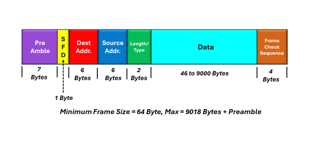
The Source Address field is a 6-byte (48-bit) field that occurs just after the Destination Address within the Ethernet frame.
I show an illustration of the IEEE 802.3 (Basic) Ethernet frame, with the Source Address field highlighted below in Figure 1.
Figure 1, Illustration of the IEEE 802.3 (Basic) Ethernet frame, with the Source Address field highlighted
Comparison to the Destination Address Field
When I was discussing the Destination Address field, I mentioned that the Destination Address field contains the address location, or the Ethernet station/port that we are sending the Ethernet frame to.
In contrast, the Source Address field contains the address of the Ethernet station, that is generating/transmitting the Ethernet frame.
Further, where the Destination Address field can contain either a Unicast (or Physical) Port Address, a Multicast, or the Broadcast Address; the Source Address field ONLY contains the Unicast (or Physical) Port Address.
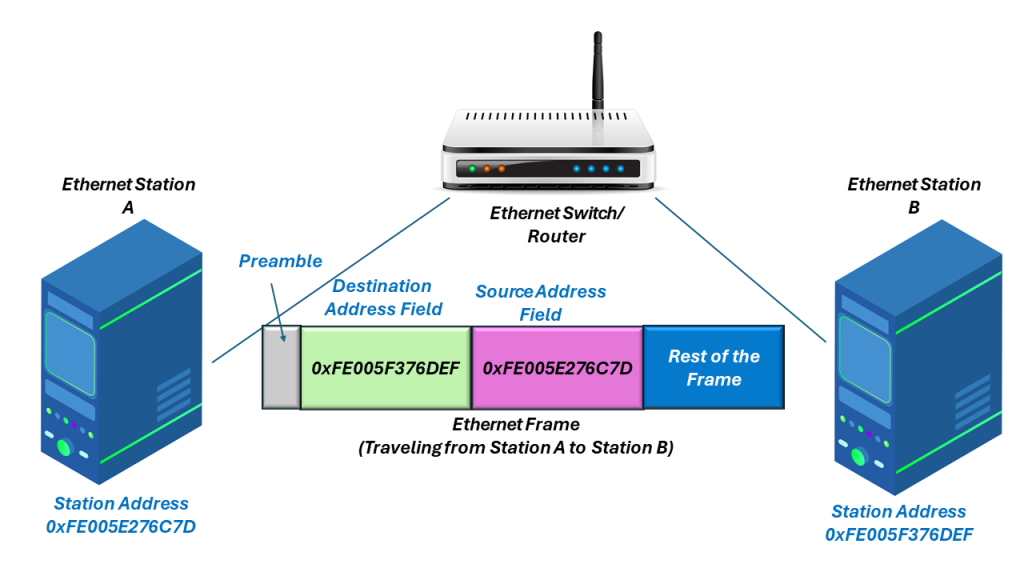
In Figure 2, I show an Ethernet station (with MAC Address 0xFE005E276C7D) sending an Ethernet frame another Ethernet station (within MAC Address 0xFE005F376DEF). I also show (how the Destination and Source Address fields, within the frame, relates to the Ethernet station addresses.
Figure 2, Ethernet station A (with MAC Address =0xFE005E276C7D) sends an Ethernet frame to Ethernet Station B (with MAC Address = 0xFE005F376DEF).
Ethernet Hardware Processing of the Source Address Field
In most cases, Ethernet switching and routing circuitry does not pay too much attention the Source Address field, within each Ethernet frame. This hardware is almost always more focused on the value of the Destination Address (and making sure the Ethernet frames are properly switched throughout the network).
However, there are cases where the Ethernet Circuitry will use and evaluate the Source Address field. Some of these cases include troubleshooting problems. Additionally, the Ethernet equipment will pay attention to the Source Address field, whenever a new router (or switch) powers up and it needs to build up a routing table (e.g., a table that associates switch ports with Ethernet addresses).
In another blog post, I discuss the Address Resolution Protocol, in which the Source Address field comes in handy.
Nonethless, the Source Address field does not typically undergo near the evaluation and processing as does the Destination Address.
This blog post defines and describes the role of the Destination Address field within the Ethernet Frame.
Introduction
The Destiination Address is a 6-byte (or 48-bit) field that follows the Preamble, within the Ethernet frame.
Whenever an Ethernet station transmits an Ethernet frame to one (or more other stations), the Destination Address identifies the intended recipient or recipients of this Ethernet frame. In other words, the Destination address identifies which station should receive this Ethernet frame.
Figure 1 shows an illustration of the IEEE 802.3 (Basic) Ethernet frame, with the Destination Address highlighted.
Figure 1, Illustration of the IEEE 802.3 (Basic) Ethernet frame, with the Destination Address highlighted.
Each Ethernet interface (or Station) is assigned a unique 48-bit address. We sometimes call this 48-bit Address the Physical, Hardware or MAC Address.
The Destination Address field (within the Ethernet frame) contains either:
The 48-bit Ethernet address that corresponds to the address of the Ethernet interface in the station (which is the destination of the frame).
As the Ethernet Receiver receives Ethernet frames, it reads the contents of every frame up to the Destination Address field. If the Destination Address value does not match the Interface’s own Ethernet address or one of the multicast or broadcast addresses that the interface is programmed to receive, then the Ethernet Receiver will ignore the rest of the Ethernet frame.
Conversely if the Destination Address value DOES match the interface’s own Ethernet address, or one of the multicast or broadcast addressse (that the interface is programmed to receive), then the Ethernet Receiver will accept and process the rest of the Ethernet frame.
The DIX Standard and the IEEE 802.3 Standards handle/interpret the Destination Address field slightly differently, as I describe below.
The DIX Standard for the Destination Address
We use the first bit of the Destination Address field (as transmitted onto the network medium) to distinguish physical addresses from multicast (or broadcast) addresses.
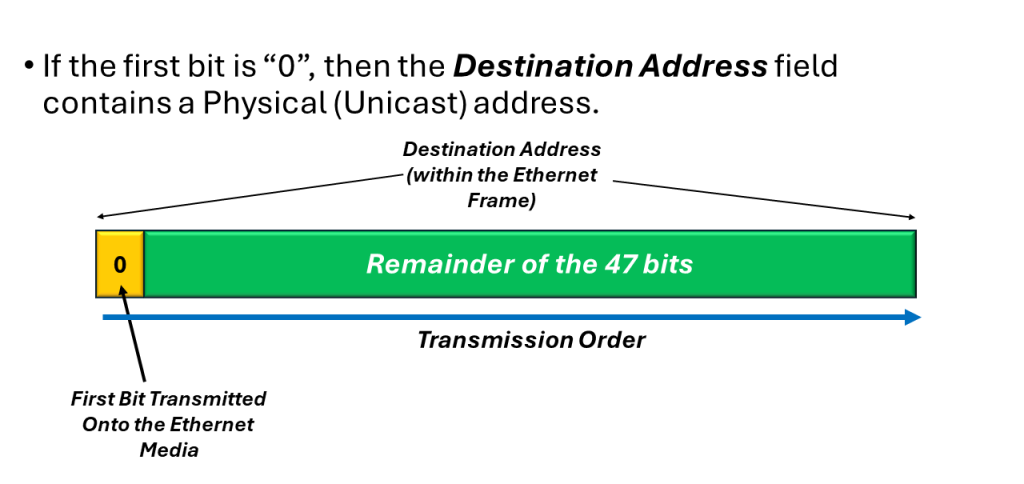
If this first bit (transmitted within the Destination Address) is zero (0), then the Destination Address field contains the physical address of an interface (or Station). We also refer to this address as the unicast address because we only send this Ethernet frame to this address only.
In Figure 2, I show an illustration of a simple “Unicast Address” within the Destination Address field.
Figure 2, Illustration of a Simple “Unicast (or Physical) Address within the Destination Address field.
Please note that in Figures 2, 3 and 4, I am showing the Transmission Order of the bits, within the Destination Address (when one Ethernet station is transmitting an Ethernet frame to another station). I will discuss the bit-ordering (within an Ethernet frame) and how we transmit bits (within the Destination Address) from one Ethernet station to another station, below.
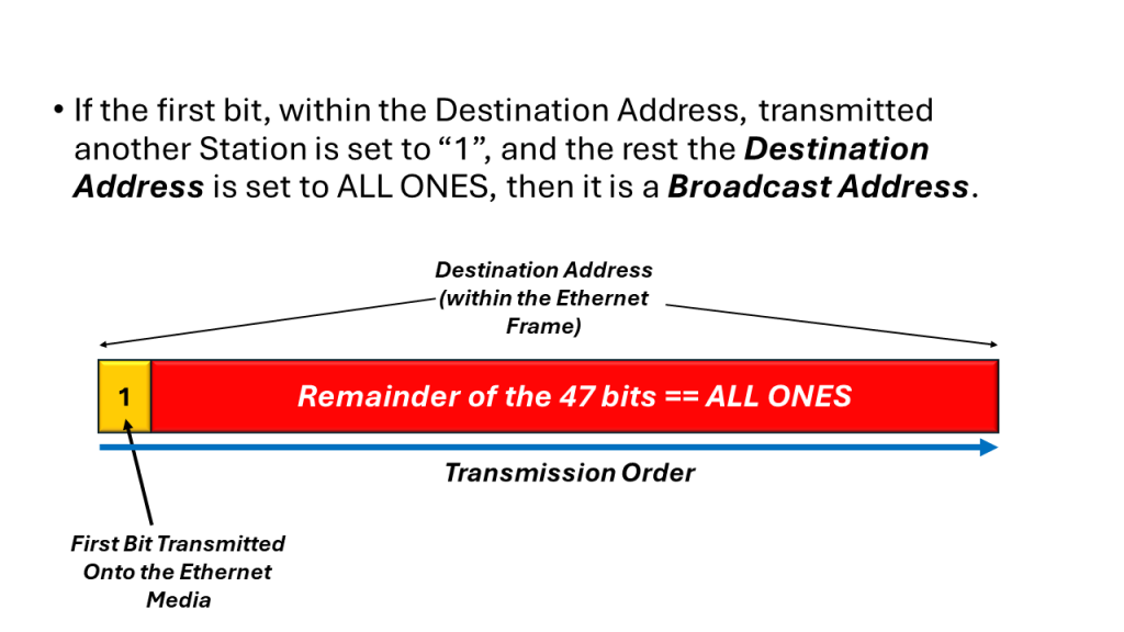
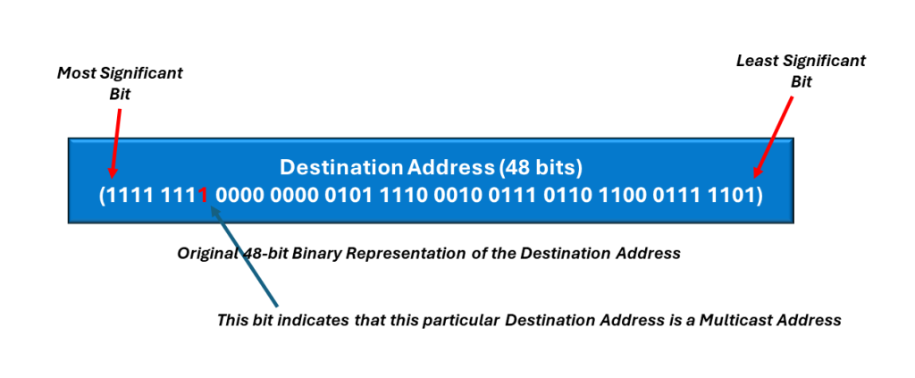
If the first bit (based on the transmission order onto the medium) is a one (1), then the Destination Address field contains a multicast address. If all 48-bits are set to “1” (e.g., an All Ones pattern), then the Destination Address field contains a broadcast (or all stations) address.
In Figure 3, I show a simple illustration of the Multicast Address, within the Destination Address field.
Figure 3, Illustration of the Multicast Address, within the Destination Address field.
In Figure 4, I show a simple illustration of the Broadcast Address, within the Destination Address field.
Figure 4, Illustration of the Broadcast Address, within the Destination Address field.
The IEEE 802.3 Standard for the Destination Address
The IEEE 802.3 standard (for the Destination Address field) interprets the first bit (transmitted within the Destination Address) the same way as for the DIX standard frames. However, IEEE 802.3 adds significance to the second bit within the Destination Address.
In this case, we use this second bit-field to distinguish between locally and globally administered addresses.
A globally administrated address is a physical address that an Ethernet Equipment Manufacturer assigned to the interface. If the network sets this 2nd bit-field is set to “0”, then this is a globally administered address.
NOTE: In the DIX Standard, we always globally administer Destination Addresses.
If the Ethernet Interface address is administered locally, then the second bit is typically set to “1”.
For example, in the case of the Broadcast Address, the 2nd bit, along with all other bits (within the Destination Address) are set to “1” in both the DIX and IEEE 802.3 standards.
NOTE: We rarely use Locally administered addresses in Ethernet networks. These days Ethernet Equipment Manufacturers assign each piece of Ethernet equipment its own unique 48 -bit Ethernet address during manufacturing. As I discuss in another blog post, these addresses are globally administered.
How We Transmit the Contents of the Destination Address
As I mentioned earlier, the Destination Address field consist of 6-bytes or 48-bits. To show the transmission order (along with the rest of the Ethernet frame), it is best to show an example.
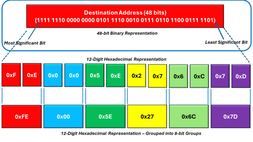
Consider an Ethernet frame with the following Destination Address (below in the highlighted portion of Figure 5).
Figure 5, Illustration of the Breakdown of the Destination Address field
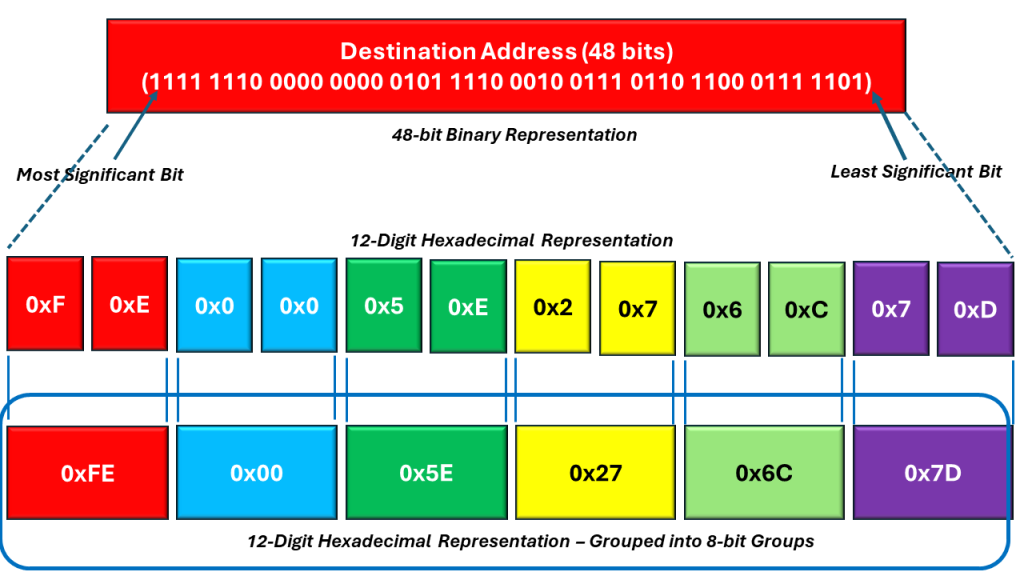
The length of the Destination Address is 48 bits (or 6 bytes). If we were to divide the bits (within this 48-bit field) into twelve (12) Nibbles, then you can express the contents within the Destination Address as 12 hexadecimal values – as I show below in the middle portion of Figure 6.
Figure 6, The Destination Address expressed as 12 (4-bit) Hexadecimal Values
We can then combine these 12 Hexadecimal bytes into 6 (two-digit) Hexadecimal Values. When we do that, then we can express the Destination Address as follows:
Figure 7, The Destination Address expressed as 6 (2 Digit) Hexadecimal Values
These 6 (2 Digit) Hexadecimal Values (of the Destination Address) are also the 6 bytes within the Desitination Address field.
The Transmission Order of the Destination Address
To transmit an Ethernet frame onto the media, we take the left-most byte (the byte in the red field) and then reverse the order of this byte (transmitting the right-most bit – within this particular byte first). We then proceed to transmit the remaining bits within this byte (all the way to the left-most bit). Next, we use the same procedure for the next byte (just to the right of this left-most byte, in the light blue field).
Figure 8 illustrates the resulting transmission order of the Destination Field, within the Ethernet frame.
Figure 8, The Transmission Order of the Destination Field, within the Ethernet field.
Determining Whether the Destination Address is a Unicast, Multicast or Broadcast Address
I mentioned that the network determines whether the Destination Address field is a Unicast, Multicast, or Broadcast address by the state of the very first bit (within the Destination Address field) that we place on the Ethernet media and transmit to the other station(s).
We stated that if the network sets this particular bit-field to “0”, then we are transmitting a Unicast Address. In Figure 9, I show that this particular Destination Address (that we are transmitting) is indeed a Unicast Address (because this first bit is set to “0”.
Figure 9, Illustration of the Destination Field, highlighting the Unicast/Multicast bit-field(Not in Transmission Order)
In Figure 9, we also show the location of this particular bit-field, within the Destination Field of the Ethernet frame. Once again, I show that we are transmitting a Unicast Address.
In Figure 10, I show an example of a Multicast Address (residing within the Destination Address field) of the Ethernet frame.
Figure 10, An Example of a Multicast Address within the Destination Address field of the Ethernet frame (Not in Transmission Order)
Finally, in Figure 11, I show an example of the Broadcast Address (residing within the Destination Address field) of the Ethernet frame.
Figure 11, Example of the Broadcast Address within the Destination Address field of the Ethernet frame. (Not in Transmission Order)
This blog post presents a brief description of the contents and role of the Preamble, within the Ethernet frame.
The Preamble is the first 64 bytes within each Ethernet frame.
In Figure 1, I show an illustration of the Ethernet frame, with the Preamble Highlighted.
Figure 1, Illustration of the Ethernet frame with the Preamble Highlighted.
The original purpose of the Preamble was to provide an Ethernet Receiver or Station (which is just starting to receive an Ethernet frame) a sequence of bits to allow for it to synchronize itself with this incoming data before it receives the actual important data within the frame.
Some Background
In early 10Mbps Ethernet, stations would only receive data from other stations when one station sent a frame to the other stations.
When there was no data to send, the stations transmitted nothing, and the line was mostly quiet.
In Figure 2, I illustrate two Ethernet stations connected, transmitting no data to each other.
Figure 2, Illustration of two Ethernet stations, connected, transmitting no data to each other.
In this quiet condition, the line (or the Ethernet connection) between the two stations is quiet, and there are almost no electrical signals or activity on the line.
Then, when a station starts to send an Ethernet frame to another station, it first sends a preamble to wake up the receiving station and allow that station to synchronize itself with the incoming data stream (which is the Ethernet frame).
A More Technical Discussion
Stated more technically, each Ethernet station (capable of receiving an Ethernet frame) has some sort of Clock-Recovery PLL (or Phase-Locked Loop). The whole purpose of the Preamble (preceding the Ethernet frame) was to allow the receiving circuitry (within the PLL) to receive this sequence of bits (or transitions within the data) and obtain synchronization with this incoming data stream (or Ethernet frame) before the important data starts to arrive (e.g., the Destination Address).
What is this Preamble?
The Preamble is mostly a repeating sequence, with a repeating “1010…” pattern. The length of this preamble is 64 bits (or 8 bytes).
Again, the purpose of this Preamble (back in the old days) was to place a sequence of electrical (or optical) transitions (e.g., repeating 1010… data) within an Ethernet line and (effectively wake up the Ethernet receiver) before the receiving station actually receives useful and meaningful information (that it needs to receive and interpret properly).
In Figure 3, I show a close-up illustration of the Preamble within an Ethernet frame.
Figure 3, Illustration of the Preamble within an Ethernet frame.
Figure 3 shows that the Preamble consists of 7 bytes of the value: 0xAA or 10101010 in binary format. However, the last byte within the Preamble is of value 0xAB (or 10101011 in binary format).
Hence, the Preamble is mostly a repeating 1010.. pattern, lasting for 64 bits (or 8 bytes).
However, depending upon which Ethernet standard you are using, the standard defines that last byte (within the Preamble) differently, as I discuss below.
The DIX Frame (or Standard)
The DIX Standard defines this entire 8-byte sequence (or 0xAA, 0xAA, 0xAA, 0xAA, 0xAA, 0xAA, 0xAA, 0xAB) as the Preamble.
I show the definition of the Preamble (per the DIX Standard) in Figure 4.
Figure 4, DIX Definition of the Preamble.
IEEE 802.3 Frame (or Standard)
The IEEE 802.3 standard defines the Preamble as 7 bytes of the repeating 0xAA strings. However, it defines the last byte of the Preamble (the byte with the value 0xAB – as the Start of Frame Delimiter (SFD) byte.
I show the definition of the Preamble (per the IEEE 802.3 standard) below in Figure 5.
Figure 5, IEEE 802.3 Definition of the Preamble
Important Things to Note about the Preamble
Whether operating in the DIX Standard or the IEEE 802.3 standard, the Preamble (or the sequence of data that stations transmit BEFORE each Ethernet frame) is the same between the two standards.
Additionally, both standards require the 8th byte to have a value of 0xAB (or 10101011 in binary format). This particular byte (known as the Start of Frame Delimiter byte in the IEEE 802.3 standard) alerts the receiving Ethernet station that the Preamble is about to end and that the very next byte is part of the Destination Address.
I show the IEEE 802.3 (Basic) Ethernet Frame format in Figure 6 below, which illustrates my last point.
Figure 6, Illustration of the IEEE 802.3 Standard (Basic) Ethernet frame.
Are Preambles Still Used in Ethernet Frames?
In modern Ethernet, we have constructed our high-speed Ethernet data-streams to behave more like CBR (or Constant Bit Rate) signals, rather than bursty streams of traffic (with long idle periods between the reception of Ethernet frames). Hence, the Preamble no longer functions as a warm-up string of data to synchronize the receiver to the incoming Ethernet frame.
However, IEEE has kept the Preamble within the Ethernet standard documents. They chose to do this in order to maintain some backward compatibility between the various flavors/types of Ethernet.
IEEE has largely kept the IEEE 802.3 (Basic) Ethernet frame, exactly the same, over the decades of development within Ethernet technology.
This blog post presents a brief description of the IEEE 802.3 (Basic) Ethernet frame. It also identifies differences between this frame and the DIX Frame.
in 1985, the Institute of Electrical and Electronic Engineers (IEEE) published their first IEEE 802.3 standard, defining their own version of the Ethernet Frame.
Over time, there were some changes to this Ethernet frame structure, and the current IEEE 802.3 (Basic) Ethernet frame is as shown below in Figure 1.
Figure 1, The IEEE 802.3 (Basic) Frame Structure/Format.
Why the Word “Basic”?
I include the word “Basic” to differentiate this format of the Ethernet frame from other IEEE 802.3 formats, such as:
These other two frames have also been standardized in IEEE 802.3. However, each of these frame formats are different from each other.
Very Similar to the DIX Frame
The IEEE 802.3 (Basic) Ethernet frame is almost identical to the DIX frame.
It can have a minimum frame length of 64 bytes and a maximum frame length of 1518 bytes (not including the Preamble). Hence, the length of this frame is identical to that of the DIX Frame.
Preamble Differences
In reality, the Preamble of the IEEE 802.3 frame is identical to that of the DIX Frame. However, the IEEE Committees have defined the Preamble differently than the DIX Consortium.
I illustrate the Preamble (within the IEEE 802.3 Basic Ethernet frame) in Figure 2.
Figure 2, Illustration of the Preamble (within the IEEE 802.3 Basic Ethernet frame).
The IEEE 802.3 Standard defines the Preamble as a 7-byte field (each byte with the value of 0xAA (or 10101010 – in binary format). This standard also defines the 8th byte (of the Preamble) as a Start of Frame Delimiter (SFD). In this case, the SFD byte always has the value of 0xAB (or 10101011 – in binary format).
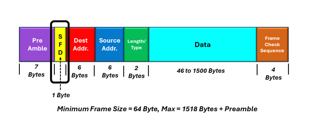
I show an illustration of the IEEE 802.3 (Basic) Ethernet frame format, with the SFD byte highlighted below in Figure 3.
Figure 3, Illustration of the IEEE 802.3 (Basic) Ethernet frame format, with the SFD byte highlighted.
Please note that although the DIX and IEEE standards define the Preamble differently, if you look closely at the byte values (of the Preamble), the Preamble for the DIX Frame and the Preamble plus SFD for the IEEE frame are identical.
The Length/Type Field
Another difference between the DIX and the IEEE 802.3 frames is in the Type or Length/Type field.
I show an illustration of the IEEE 802.3 (Basic) Ethernet frame, with the Length/Type field highlighted in Figure 4.
Figure 4, Illustration of the IEEE 802.3 (Basic) Ethernet frame format, with the “Length/Type” field highlighted.
The first version of the IEEE 802.3 standard (published in 1985) defined this particular field as the Length field. However, in 1997, the IEEE 802.3 Committee changed this field to the Length/Type field, to be compatible with the DIX Standard.
How Does the Length/Type Field Work?
The current standards define the Length/Type field as follows:
If the Length/Type field value is 1500 (or 0x05DC in Hexadecimal)
If the Length/Type field is 1500 or less (or 0x05DC in hexadecimal), then this 16-bit field will function as the Length field. The value of the Length/Type field will then reflect the number of octets within the Data field of the Ethernet frame.
If the Length/Type field value is greater than 1536 (or 0x0600 in Hexadecimal) – Compatible with DIX Frame
If the Length/Type field is greater than 1536 (0x0600 in hexadecimal), then this 16-bit field will function as a Type field. In this case, the value of the Length/Type field indicates the type of protocol data that the Ethernet frame is carrying (similar to DIX frames).
In another blog post, I present a list of standard values for the Length/Type field (when the value is greater than 1536), along with their meaning.
I identify the location of the Preamble within the DIX frame below in Figure 2.
Figure 2, The Location of the Preamble within the DIX Frame.
The main difference between the Preamble, within the DIX Frame, and that within the IEEE 802.3 (Basic) Frame is how they are defined.
I also show the byte format of the Preamble within the DIX frame below in Figure 3.
Figure 3, The Byte-format of the Preamble within the DIX Frame.
I will list the characteristics/features of the Preamble below.
Consists of 8-bytes
The first seven (7) bytes contain the value of 10101010
The 8th byte contains the value: 10101011
The last two bits (of the Preamble) are set to “[1, 1,]” to denote the end of the Preamble and the start of the Destination Address field.
The Type Field
I show the location of the Type field (within the DIX Frame), below in Figure 4.
Figure 4, Illustration of the Location of the Type-Field within the DIX Frame.
In the DIX Standard, the Type field is a 16-bit field containing an identifier that indicates the type of high-level protocol data we are carrying within the Data Field of the Ethernet Frame.
For example, if the Type field is set to 0x0800, then the Data Field (within this particular Ethernet frame) is transporting data that supports the IP (Internet Protocol).
In another blog post, I present a list of standard values for the Type field.
The IEEE 802.3 (Basic) and the other IEEE 802.3-compliant Ethernet frames all use the Type/Length for this 2-byte position within the Ethernet frame.
I have defined the Destination Address, Source Address, Data Field, and Frame Check Sequence fields in other blog posts.
This blog post presents an overview of the various types of Ethernet frames, that are in use today.
The purpose of this blog post is to list, itemize, and briefly describe the various types of Ethernet frames that are in use today.
This blog post will also provide links to blog posts with more details about these various Ethernet frames and the various fields (within these frames).
In short, there are five different types of Ethernet frames (that are widely used in networking today).
We call this type of a frame a “Q-Tag” frame, because it includes the IEEE 802.1Q Tag. The literature also calls this tag the VLAN or priority tag. We discuss VLAN (Virtual LANs) in another post.
I illustrate the IEEE 802.3 Compliant Frame with Q-Tag below in Figure 3.
Figure 3, Illustration of the IEEE 802.3 Compliant Frame with Q-Tag.
The maximum length of the IEEE 802.3 Frame (with Q-Tag) is 1522 bytes (plus Preamble).
I present a more detailed description of the IEEE 802.3 Compliant Frame – with Q-Tag, in another blog post.
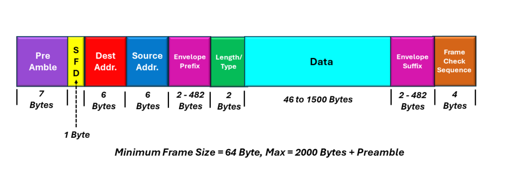
IEEE 802.3 Complaint Ethernet Frame with Envelope Prefix and/or Suffix
I illustrate the IEEE 802.3 Compliant Ethernet Frame with Envelope Prefix and/or Suffix, below in Figure 4.
Figure 4, Illustration of the IEEE 802 Compliant Ethernet Frame with Envelope Prefix and/or Suffix
The IEEE 802.3 Compliant – Envelope Frames, can have a maximum length of 2000 bytes (plus the Preamble).
I present a more detailed description of the IEEE 802.3 Compliant Ethernet frame with Envelope Prefix and Suffix in another blog post.
Jumbo Frame
I illustrate the Jumbo Frame before in Figure 5.
Figure 5, Illustration of the Jumbo Frame
The Jumbo Frame can be a large as 9018 bytes (in length) plus the Preamble.
I present a more detailed description of the Jumbo Ethernet frame in another blog post.
This blog post briefly defines the term Broadcast Communication. It also contrast Broadcast Communication with the terms Unicast and Multicast Communication.
In Computer Network Architecture, the three types of communication are:
These forms of communication can occur in Layer 2 (the Data Link Layer) and Layer 3 (the Network Layer).
NOTE: Layer 2 is the Data Link Layer. At this layer, the switch device works using MAC addresses for communication. Layer 3 is the Network Layer, where the router device uses the IP addresses for communication.
In this case, the word “cast” refers to how many people or devices we send data to. As I mentioned above, we can send data in a unicast, multicast, or broadcast manner.
I will briefly define these terms below.
Unicast Communication
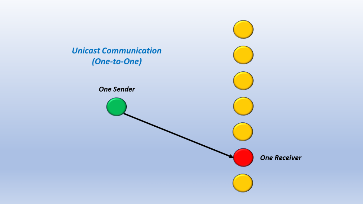
Unicast: Means one-to-one communication. In this case, a single sender sends data to a single receiver or device.
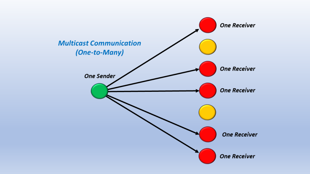
Multicast: This means one-to-many communication. In this case, a single sender sends data out to multiple devices in parallel. However, Multicast communication does not involve ALL DEVICES. Some devices on the network are excluded from this communication. This makes Multicast Communication different from Broadcast Communication.
Figure 2, Illustration of Multicast Communication.
Broadcast Communication
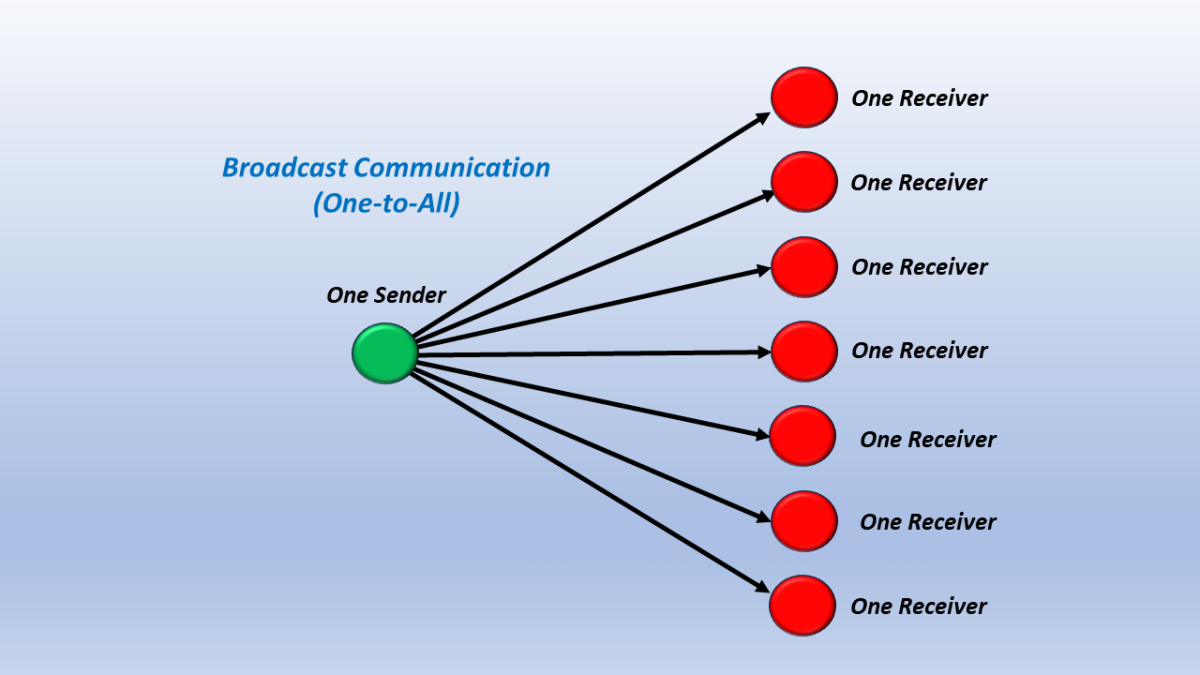
Broadcast: Means one-to-all communication. In this case, a single sender sends data to ALL network devices. Broadcast is different from Multicast Communication in that (for Broadcast) the sender sends information to ALL devices and excludes no one.
I show a simple illustration of Broadcast Communication below in Figure 3.
Figure 3, Illustration of Broadcast Communication.
What is Broadcast Communication?
Broadcast is a type of data transmission where data is sent from one device to all devices on a network.
In a Broadcast transmission, every packet is addressed to the network’s broadcast address. This means that every device on the network will receive the packet.
It is a one-to-all transmission which means there is one sender, but the information is delivered to all the connected receivers.
Broadcast is used for scenarios where a single device must communicate with all network devices.
We mainly use the term “broadcast” for cable TV transmission, where a broadcast sends TV signals from one source (one point) to all the possible destinations (all points).
Broadcast Communication is useful in network management packets such as ARP (Address Resolution Protocol) and RIP (Routing Information Protocol), where all the devices must see the data.
NOT All Network Technologies support Broadcast Communication.
Not all network technologies support Broadcast addressing. X.25 nor Frame Relay do not support broadcast communication.
IPv4 (Internet Protocol Version 4), which is and has been the primary networking protocol for Packet-Switching communication, supports Broadcast Communication. However, in this case, the broadcast domain is the broadcasting host subnet (which is typically small). There is no way to do an internet-wide broadcast. Broadcasting is mainly confined to the local area network (e.g., Ethernet).
IPv6, which is intended to be the successor to IPv4, does not support broadcast communication. IPv6 relies on multicast addressing/communication instead.
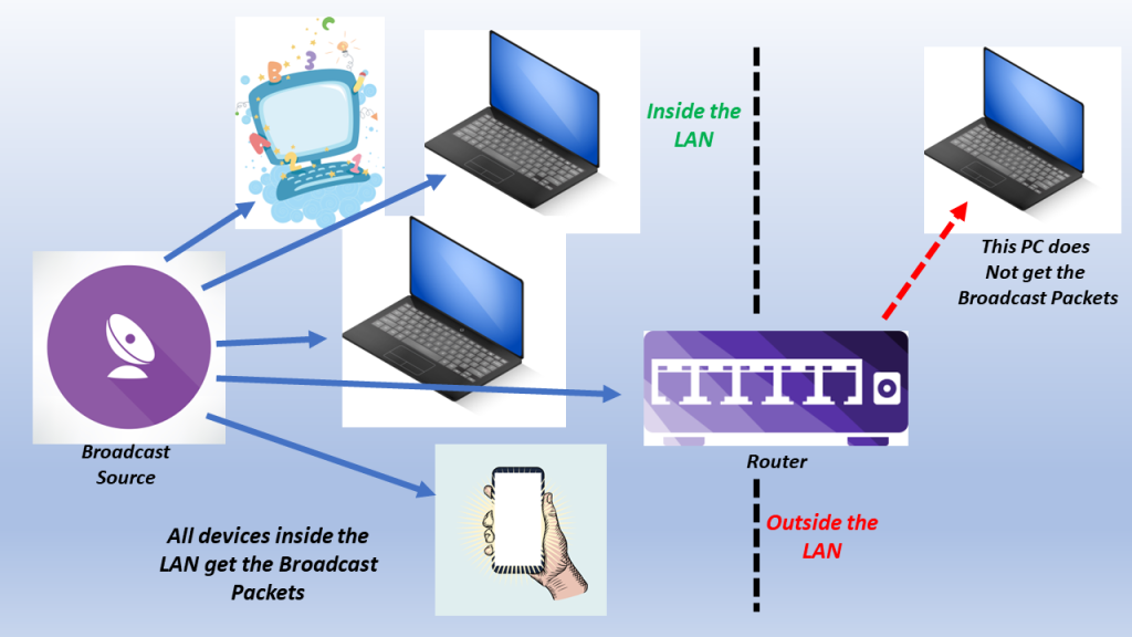
I show an illustration of Limited Broadcast Communication below in Figure 4.
Figure 4, Illustration of Limited Broadcast Communication.
Figure 4 shows that all packets will go to each receiver within the LAN for Broadcast Communication. However, this form of communication does not go past the router (which is outside of the LAN). Broadcast Communication is mostly for LAN-only communication.
Broadcast Communication is mainly for “within a LAN” communication. In other words, it only sends packets to devices within its Local Area Network.
When working with IPv4 packets, the Broadcast Address is 255.255.255.255. Whenever the Broadcast sends packets to this Broadcast Address, all devices (within the LAN) will receive these packets.
Unicast and Multicast do not have this restriction. These forms of communication can send packets outside of their LANs.
Broadcast Communication within an Ethernet Network
I present how we can support Broadcast Communication within the Destination Address field, in an Ethernet frame, in another post.
These forms of communication can occur in Layer 2 (the Data Link Layer) and Layer 3 (the Network Layer).
NOTE: Layer 2 is the Data Link Layer. At this layer, the switch device works using MAC addresses for communication. Layer 3 is the Network Layer, where the router device uses the IP addresses for communication.
In this case, “cast” refers to how many people or devices we send data to. As mentioned above, we can send data in a unicast, multicast, or broadcast manner.
I will briefly define these terms below.
Unicast Communication
Unicast: Means one-to-one communication. In this case, a single sender sends data to a single receiver or device.
Multicast: This means one-to-many communication. In this case, a single sender sends data to multiple devices in parallel.
However, Multicast communication does not involve ALL DEVICES. Some devices on the network are excluded from this communication. This makes Multicast Communication different from Broadcast Communication.
I show a simple illustration of Multicast Communication below in Figure 2.
Figure 2, Illustration of Multicast Communication.
Broadcast Communication
Broadcast: Means one-to-all communication. In this case, a single sender sends data to ALL network devices.
Broadcast is different from Multicast Communication in that (for Broadcast) the sender sends information to ALL devices and excludes no one.
Figure 3, Illustration of Broadcast Communication.
What is Multicast Communication?
Multicast is a type of data transmission where data is sent from one device to a group of devices on a network.
It is a type of one-to-many communication where a single packet of data is transmitted to multiple recipients simultaneously.
In a Multicast transmission, a single packet is addressed to a group of devices rather than to a single device like in Unicast. The packet is then replicated and sent to all devices in the group, allowing for more efficient network resource use.
Every packet is addressed to a multicast group address in a Multicast transmission. This means that only devices that have subscribed to the multicast group will receive the packet.
This characteristic (of communicating with many, but NOT ALL, receivers) makes multicast communication different from broadcast communication (in which a single device sends packets to ALL devices within the network).
Multicast transmission is widely used in applications such as video streaming, online gaming, and real-time communication, where the same data must be sent to multiple recipients simultaneously. For example, a video streaming application sends a video stream to a group of users watching the same video.
Examples of Applications using Multicast Communication
PPV Services for Events such as boxing matches or World Cup (Soccer Matches).
Streaming Services, such as Netflix, Sling, Hulu, Amazon Prime Video, and Disney+.
I show a simple illustration of Multicast Communication to realize a Live-Streaming Service below in Figure 4.
Figure 4, Illustration of Multicast Communication to realize a Live-Streaming Service.
Multicast Communication within Ethernet
I discuss how we support Multicast Communication within the Destination Address of an Ethernet frame, in another blog post.
This blog post briefly defines the term Unicast Communication. It also contrast this term with the definitions for Multicast and Broadcast Communication.
In Computer Network Architecture, the three types of communication are:
These forms of communication can occur in Layer 2 (the Data Link Layer) and Layer 3 (the Network Layer).
NOTE: Layer 2 is the Data Link Layer. At this layer, the switch device works using MAC addresses for communication. Layer 3 is the Network Layer, where the router device uses the IP addresses for communication.
In this case, the word “cast” refers to how many people or devices we send data to. As mentioned above, we can send data in a unicast, multicast, or broadcast manner.
I will briefly define these terms below.
Brief Definition of Unicast Communication
Means one-to-one communication. In this case, a single sender sends data to a single receiver or device.
I show a simple illustration of Unicast Communication below in Figure 1.
Figure 1, Illustration of Unicast Communication.
Brief Definition of Multicast Communication
This means one-to-many communication. In this case, a single sender sends data out to multiple devices in parallel. However, Multicast communication does not involve ALL DEVICES. Some devices on the network are excluded from this communication. This makes Multicast Communication different from Broadcast Communication.
I show a simple illustration of Multicast Communication below in Figure 2.
Figure 2, Illustration of Multicast Communication.
Brief Definition of Broadcast Communication
Means one-to-all communication. In this case, a single sender sends data to ALL network devices. Broadcast is different from Multicast Communication in that (for Broadcast) the sender sends information to ALL devices and excludes no one.
Figure 3, Illustration of Broadcast Communication.
What is Unicast Communication?
In a Unicast transmission, a single sender sends data to a single receiver.
In this case, every packet (or frame) is addressed to a specific device on the network. We use unicast communication for point-to-point communication, where a single device (or station) communicates with another device or station.
Generally, we use unicast communication to send a message, browsing a website, downloading a file, etc.
Examples of Unicast Communication
If a device has an IP address of 21.2.4.0 in a network and wishes to transmit a packet to a device with an IP address 32.12.5.0 (in a different network).
I show an illustration of this below in Figure 4.
Figure 4, Illustration of a PC (with an IP address of 21.2.4.0) transmitting a packet to a device with an IP address of 32.12.5.0
4 computers are connected to a switch. If computer # 3 wants to directly communicate with computer # 2; this is unicast communication.
I show an illustration of this example below in Figure 5.
Figure 5, Illustration of 4 Computers connected together via a switch. Computer # 3 is now communicating with Computer # 2.
Whenever we use a computer to browse a website, the web server acts as a sender, and our computer acts as the receiver.
In Figure 6, I show an illustration of this particular example.
Figure 6, Computer (operating a web browser) while connected to a Web Server.
Downloading a file from an FTP server is an example of unicast transmission. In this case, the FTP server is the sender, and our computer is the receiver.
Unicast Communication within Ethernet
I provide a brief discussion on Unicast Communication and we use that within the Destination Address of an Ethernet frame, in another blog post.
The Running Disparity (or RD) is defined as the difference between the number of logic 1 bits and logic 0 bits between the start of a data sequence and a particular instant in time during its transmission.
What is Running Disparity (RD)?
We define the Running Disparity (or RD) as the difference between the number of logic 1 bits and logic 0 bits between the start of a data sequence and a particular instant in time during its transmission.
In other words, the RD for a character is the difference between the number of logic 1 bits and logic 0 bits in that character.
Hence, if there are more logic 1 bits than logic 0 bits (within a character or string of consecutive bits), we can state that the RD is positive.
If there are more logic 0 bits than logic 1 bits, then we can state that the RD is negative.
Finally, if the number of logic 1 and logic 0 bits are the same, we can state that the RD is neutral or zero.
We can express the Running Disparity as either an integer or as a ratio:
EXPRESSING RD AS AN INTEGER NUMBER:
If you wish to express the RD of a character or string (of consecutive bits) as an integer number, then you can calculate the RD with the following equation:
RD = (Number of Logic 1 bits in the character or string) – (Number of Logic 0 bits in the character or string)
For example:
The running disparity of the hexadecimal expression of 0x78 is 0.
To understand why this is the case, if we were to express this value in its binary format, we get 0111 1000. The binary expression (for this value) contains four 0s and four 1s.
Thus, RD = 4 – 4 = 0
On the other hand, the running disparity of the hexadecimal expression of 0x7F is +6.
Again, if we were to express this value in its binary format, we would get 0111 1111. The binary expression (for this value) contains seven 1s and one 0.
Hence, RD = 7 – 1 = +6
EXPRESSING RD AS A RATIO:
If you wish to express the RD of a character or string (of consecutive bits) as a ratio, then you would do the following:
Count the total number of logical “1s” in the expression.
Count the total number of logical “0s” in the expression.
And then express this information in the following format:
Number of Logical 1s (in character/string) : Number of Logical 0s (in character/string)
For example:
We express the running disparity of the hexadecimal expression of 0x78 as:
4:4, which we can reduce (or simplify) to 1:1.
Likewise, we can compute and express the RD for the value 0x7F as 7:1.
Some communication and data storage system standards (such as Gigabit Ethernet/1000BASE-X, Fibre-Channel, etc.) require that we maintain the RD as near to neutral as possible.
The system designer must ensure that the ratio of logical 1 bits to logical 0 bits (over time) should be kept close to 1:1.
Thus, the System Designer must follow any character/string with negative disparity with another character/string with an equal amount of positive disparity, and vice-versa.
Keeping RD to a minimum is to maintain dc balance on the transmission medium.
The System Designer must ensure that the RD does not increase without bounds.
The 8B/10B line code is a specific example of a line code that requires and exercises control over RD.
NOTE: Controlling and monitoring RD can also help detect transmission errors.
Has Inflaton got You Down? Our Price Discounts Can Help You Fight Inflation and Help You Become an Expert on OTN!! Click on the Banner Below to Learn More!!