What does the expression 100GBASE-R Mean?

This post defines and describes the expression 100GBASE-R for 100Gbps Ethernet Applications.


What does the expression 100GBASE-R Mean?

For Ethernet applications, the IEEE 802.3 standard states that the term 100GBASE-R represents a group (or family) of Physical Layer (e.g., 100Gbps Transceiver) devices that do the following:

  • When it transmits its data towards the PMD (Physical Medium Dependent) device, it will:
    • Encode the CGMII data into the 64B/66B PCS (Physical Coding Sublayer) code.
      • This is what the -R suffix means, by the way.  
    • Divide (or de-multiplex) its outbound traffic into 20 PCS Lanes by routing each 66b (66 bit) block to a different PCS lane (in a round-robin manner).
    • It will often multiplex these 20 PCS Lanes into 4 or 10 physical (or electrical) lanes for CAUI-4 and CAUI-10 applications, as it transports this data to an Optical Transceiver (or PMD), respectively.
  • When it receives data (from the PMD), it will:
    • De-multiplexes these CAUI-4/CAUI-10 physical (or electrical) lanes of traffic that it receives from the Optical Transceiver into 20 PCS Lanes.
    • Combines (or multiplexes) these 20 PCS Lanes into a single stream of traffic as it routes this data towards the MAC (Media Access Control) device.
    • Decodes this data from the 64B/66B PCS code back into the CGMII (100Gbps Media Independent Interface) format.  

NOTE:  I discuss some of this processing (with 100GBASE-R data) for ITU-T G.709, Annex E mandated handling (before GMP Mapping this data into the OPU4 Payload) in Lesson 10; within THE BEST DARN OTN TRAINING PRESENTATION…PERIOD!!!

In Summary

In summary, these 100Gbps Ethernet devices will encode their “outgoing” data into the 64B/66B PCS code before transmitting it over some media.  

These 100Gbps Ethernet devices will also decode their “incoming” data from the 64B/66B PCS code (to restore the data to its original CGMII content) as it receives this data.

In other words, the 100Gbps Ethernet system will encode this data into the 64B/66B PCS format solely to transport this data across the communication media.  

Once this Ethernet data has arrived (at the other end of the media), the Ethernet system will decode this data (from the 64B/66B PCS format) to restore it to its original content.

The bit rate of this 64B/66B PCS encoded 100Gbps Ethernet data stream is 103.125Gbps ‡ 100pm.

Why Do We Encode our 100Gbps Ethernet Data into this 64B/66B PCS Code before we transmit this data over Optical Fiber?

We encode this 100Gbps Ethernet (CGMII) data into this 64B/66B PCS Code before we:

  • Transmit this data over Optical Fiber, or
  • Map this data into an OPU4 Frame (again for transmission over Optical Fiber).

There are several reasons we encode this data (before transmission over Optical fiber).  But the main goals are to convert this data into a more conducive format for transport over Optical Fiber.  More specifically, by converting this data into the 64B/66B code, we:

  • Minimize Running Disparity (e.g., maintain DC balance) with our data, and 
  • Ensure that we have no long strings of consecutive “1s” or consecutive “0s” within the data, we transport over Optical Fiber.  
  • Offer greater management capability (within our 100Gbps signal) by including Sync Bits within our 66-bit blocks.   These Sync bits permit us to designate certain 66-bit blocks as data blocks and other 66-bit blocks as control blocks.  I discuss some of this in detail in Lesson 10 within THE BEST DARN OTN TRAINING PRESENTATION…PERIOD!!!

Clueless about OTN? We Can Help!!! Click on the Banner Below to Learn More!!!

Discounts Available for a Short Time!!

The Various 100GBASE-R Transceiver Devices

IEEE 802.3 also states that the Physical Layer (Transceiver devices) supporting the following standards must support the 100GBASE-R PCS encoding/decoding scheme.

  • 100GBASE-CR4
  • 100GBASE-CR10
  • 100GBASE-SR4
  • 100GBASE-SR10
  • 100GBASE-KP4
  • 100GBASE-KR4
  • 100GBASE-LR4
  • 100GBASE-ER4

Please check out the post on 64B/66B encoding to learn more about that encoding scheme.

Where is this PCS Encoder/Decoder Located?

IEEE 802.3 states that the 100GBASE-R PCS block (e.g., the entity that performs the PCS Encoding/Decoding) resides between the Reconciliation Layer and the PMA (Physical Medium Attachment), as shown in Figure 1 below.

IEEE 802.3 100Gbps Ethernet Architectural Diagram

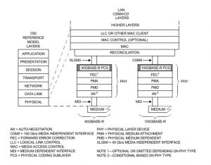
Figure 1, Architectural Positioning of 100Gigabit Ethernet (from the IEEE 802.3 Standard)

But, in a real system, this PCS Encoder/Decoder often resides in the same IC containing the MAC (Media Access Controller).  

Figure 2 illustrates a MAC that includes the PCS Encoder and Decoder functions.

100GBASE-R Encoder and Decoder in MAC IC

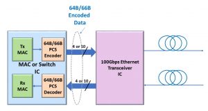
Figure 2, Illustration of a Connection between the MAC and a 100Gbps Transceiver IC

This figure also shows the MAC or Switch IC exchanging data with the 100Gbs Ethernet Transceiver IC over a CAUI-4 or CAUI-10 Interface.

Has Inflation got You Down? Our Price Discounts Can Help You Fight Inflation and Help You Become an Expert on OTN!! Click on the Banner Below to Learn More!!!

Temporary Discounts Available Now!!

What is the PSI – Payload Structure Identifier Byte

This post describes the role of the PSI (Payload Structure Identifier) byte, within the OPUk Overhead, is used within the OTN.

What is the PSI – Payload Structure Identifier (Byte and Message)?

The PSI Byte

The PSI (or Payload Structure Identifier) byte is an Overhead byte within the OPUk structure.

Figure 1 presents an OPU frame with the location of the PSI byte identified.

Generic OPU Frame with PSI Byte Highlighted

Figure 1, Illustration of an OPUk Frame Structure with the Overhead Bytes (along with the PSI Byte) Identified  

The purpose of the PSI byte is to permit an OTN Path Terminating Equipment (PTE) to transport a 256-byte PSI (payload structure identifier) message throughout the OTN (Optical Transport Network).

The primary purpose of this 256-byte PSI Message is to permit the Source PTE to alert the OTN (Network) of the type of data (or traffic) we are transporting within this particular OPU data stream.

Since each OPUk frame contains only 1 PSI byte, an OTN PTE will have to transmit 256 consecutive OPU frames to transmit this PSI message completely.

The OTN PTE will align its transmission of this 256-byte PSI message with the MFAS byte.

Please see the OTUk Frame Structure post for more information on the MFAS byte.

In other words, whenever the OTN PTE is transmitting an OTUk frame with the MFAS byte set to “0x00”, then the OTN PTE will also be sending the first byte of the PSI message (e.g., PSI[0]) via the PSI byte-field.

Likewise, whenever the OTN PTE is transmitting an OTUk frame with the MFAS byte set to “0x01”, then the OTN PTE will also be sending the second byte within this 256-byte message (e.g., PSI[1]) via the PSI byte field, and so on.

Two Types of PSI Messages

An OTN Source PTE will transport one of two types of PSI Messages.

  • The Non-Multiplexed Traffic – PSI Message, and
  • The Multiplexed Traffic – PSI Message.

I will describe each of these types of PSI Messages below.  

The Non-Multiplexed Traffic PSI Message

We will use the Non-Multiplexed Traffic PSI Message when transporting Non-Multiplexed Traffic within our OPU data stream.

Examples of Non-Multiplexed Traffic would be:

  • Transporting 1000BASE-X via an OPU0 signal
  • 10GBASE-R via an OPU2e signal.
  • 100GBASE-R via an OPU4 Signal.

In other words, we are handling Non-Multiplexed Traffic whenever we only transport a single Non-OTN client signal via this OPUk data stream.  

I present an illustration of an OPU Frame, with the PSI field highlighted (along with a break-out of the Non-Multiplexed Traffic type of PSI Message) below in Figure 2.

OPU Frame with PSI Byte-Field highlighted and a Breakout of the Non-OTN Client/Non-Multiplexed PSI Message

Figure 2, Illustration of an OPU Frame, transporting the Non-Multiplexed traffic of PSI Message

NOTE:  The easiest way to tell if you’re working with the Non-Multiplexed Traffic type of PSI Message is to check and see if you see the CSF (Client Signal Fail) bit-field in PSI Byte # 2.

If the CSF bit-field is present, you’re dealing with the Non-Multiplexed Traffic type of PSI Message.

If the CSF bit-field is NOT present (within the PSI Message), then you are dealing with the other type of PSI Message.

The Multiplexed Traffic Type of PSI Message

We use the Multiplexed Traffic type of PSI Message anytime we work with an OPU server signal transporting numerous lower-speed ODUj Tributary Signals.

For example, if we mapped and multiplexed 80 ODU0 tributary signals into an OPU4 server signal, then this OPU4 signal would transport the Multiplexed Traffic type of PSI Message.

Figure 3 presents an illustration of an OPU Frame, with the PSI field highlighted, along with a break-out of the Multiplexed Type of PSI Message.

OPU Frame with PSI Byte-Field Highlighted and a Breakout of the Multiplexed Structure PSI Message

Figure 3, Illustration of an OPU Frame transporting the Multiplexed Traffic Type of PSI Message

Again, one big difference between the Multiplexed Traffic type of PSI Message and that for Non-Multiplexed Traffic is that the Multiplexed Traffic type of PSI Message will not have the CSF (Client Signal Fail) bit-field.

New Comprehensive OTN Training…Available Now. Click on the Banner Below to Learn More!!

Discounts Available for a Short Time!!!

The PSI Message

The PSI (Payload Structure Identifier) message is a 256-byte message that an OTN terminal will transport via the PSI byte for 256 consecutive OPUk/ODUk/OTUk frames.

Let’s talk a little bit about the data that we are transporting within these PSI Messages.  

PSI[0] – or PSI Byte # 0 – PT (Payload Type)

The first byte of the PSI Message (e.g., PSI[0]) carries the Payload Type (or PT) value.  The PT byte identifies the type of client data the OPUk structure is transporting via its payload.  

First, Table 1 presents a list of standard PT values and the corresponding client data types (being transported within the OPUk Structure).

Table 1a, PT (PSI[0]) Values, and the Corresponding Client Data within the OPUk Structure – Part I

PT - Payload Type - PSI Byte - Client Signal into OPUk

Table 1b, PT (PSI[0]) Values, and the Corresponding Client Data within the OPUk Structure – Part II

PT - Payload Type - PSI Byte - Client Signal into OPUk

NOTES: 

  1. We will discuss the PT = 0x07 case when mapping 100GBASE-R into an OPU4 in Lesson 4.  
  2. Access to Lesson 4 requires that you have a membership to “THE BEST DARN OTN TRAINING PERIOD” training.

Table 1c, PT (PSI[0]) Values, and the Corresponding Client Data within the OPUk Structure – Part III

PT - Payload Type - PSI Byte - Client Signal into OPUk

NOTE: 

  1. We will discuss cases where PT = 0x20 and 0x21 in Lesson 5.  
  2. Access to Lesson 5 requires that you have a membership to “THE BEST DARN OTN TRAINING PERIOD” training.

Table 1d, PT (PSI[0]) Values, and the Corresponding Client Data within the OPUk Structure – Part IV

PT - Payload Type - PSI Byte - Client Signal into OPUk

Other posts contain detailed information on how ITU-T G.709 recommends that the System Designer map each client signal into their corresponding OPUk structure.

Click HERE for more information about the PT = 0x21 Method for Mapping/Multiplexing Lower-Speed ODUj signals into a Higher-Speed ODUk Signal.

The Remaining Bytes within the PSI Message

PSI bytes 1 and 3 through 255 are for “Mapping and Concatenation Specific” roles that we will discuss in another post. 

In Multiplexed-Traffic Type of PSI Messages

For the Multiplexed-Traffic type of PSI Message, we use these bytes to transport MSI (Multiplex Structure Identifier) information throughout the OTN.  

In other words, we will transport the MSI information (via these PSI Messages) for applications in which we are mapping/multiplexing lower-speed ODUj tributary signals into higher-speed OPUk/ODUk server signals.

The MSI aims to identify these lower-speed ODUj tributary signals we are transporting via this OPUk/ODUk signal to the OTN.  

You can think of the MSI as a passenger list or manifest of lower-speed ODUj tributary signals riding along (or being transported) within this OPUk server signal.  

In Non-Multiplexed-Traffic Type of PSI Messages

PSI byte 2, Bit 1 (for the Non-Multiplexed Traffic PSI Message) is the CSF (or Client Signal Fail) indicator.  The ITU-T Standards Committee has reserved PSI Byte 2, Bits 2 through 8 for “future standardization.”

We discuss the CSF indicator and the MSI information in other posts.

We also extensively discuss these PSI Messages within THE BEST DARN OTN TRAINING PRESENTATION….PERIOD!!!.  

You can click on the Banner below to learn more our this training package.

Has Inflation got You Down? Our Price Discounts Can Help You Beat Inflation and Help You Become an Expert on OTN!!  Click on the Banner Below to Learn More.

Discounts Available for a Short Time ONLY!!

For More Information on OTN-Related Posts in this Blog, click on the image below.

OTN Related Blog

OTN Related Topics within this Blog

OTN Related Topics within this Blog General Topics Consequent Equations - What are they and How can you use them? ...

The BMP (Bit-Synchronous Mapping Procedure)

This post describes the Bit-Synchronous Mapping (BMP) for mapping non-OTN CBR client signals into an OTN signal.


What is the BMP (Bit-Synchronous Mapping Procedure)?

This post describes the BMP (Bit-Synchronous Mapping Procedure) for mapping a non-OTN CBR (Constant Bit Rate) client signal into an OPUk/ODUk signal.

NOTE:  Whenever ITU-T G.709 discusses procedures for mapping a client signal into an OPUk/ODUk signal, it will often refer to the OPUk/ODUk signal as the Server signal.  

Therefore, we will use the terms OPUk/ODUk and Server interchangeably throughout the remainder of this post.

ITU-T G.709 also defines two other mapping procedures that one can use to map a non-OTN CBR client signal into a Server signal.

(*) – Requires membership to THE BEST DARN OTN TRAINING PRESENTATION…PERIOD!!  to see this post.  

We discuss each of these other two mapping procedures in other posts.

What is the Bit-Synchronous Mapping Procedure?  

The name Bit-Synchronous Mapping Procedure means that there is a bit-synchronous relationship between the client signal (that we are mapping into an OPUk payload) and the bit rate of the OPUk payload.

In other words, the System Designer must ensure that ALL the following conditions are true before they can use the Bit-Synchronous Mapping Procedure to map a particular client signal into the OPUk payload.

  • The OPUk/ODUk/OTUk clock signal must be phase-locked (or synchronized) to the client clock signal, as Figure 1 illustrates below.

Timing Requirements between Client Signal and OPUk/ODUk Signal to use Bit Synchronous Mapping Procedure - BMP

Figure 1, Illustration of the Synchronization Requirements (between the OPUk/ODUk/OTUk signal and the client signal) to use BMP

  • We must use fixed-stuffing to handle rate differences (between the Client signal and OPUk/ODUk/OTUk signal).
    • In other words, we insert a fixed number of bits/bytes into the Server (OPUk) payload, along with the client data.
      • OPUk_rate = Client_rate + (Fixed_Stuff x Server_Frame_Rate);
  • Client bit-rate tolerances MUST NOT exceed the Server bit-rate tolerances.
    • For example, if the bit-rate tolerance for an OPUk is +/-20ppm, then the Client signal’s bit rate tolerance cannot exceed +/-20ppm.

New Comprehensive OTN Training…Available Now. Click on the Banner Below to Learn More!!!

Discounts Available for a Short Time!!

ITU-T G.709 Recommendations on Using BMP

ITU-T G.709 recommends using BMP when mapping the following non-OTN Client Signals into each of the OPUk/ODUk Structures listed below in Table 1.

Table 1, List of Client Signals that ITU-T G.709 Recommends using BMP when mapping into an OPUk Structure

ITU-T G.709 Recommendations for the Bit-Synchronous Mapping Procedure (BMP)

BMP and De-Mapping Jitter

BMP offers the best de-mapping jitter of the three recommended Mapping Procedures.  

Fixed stuffing and the presence of the OTUk/ODUk/OPUk overhead bytes are the only contributions to mapping (and de-mapping jitter).  Justification events (which imposes 8UI-pp of mapping-related jitter) for AMP applications do not occur in BMP.

However, the System Designer will still need to implement a clock-smoothing or jitter attenuation scheme to comply with de-mapping jitter requirements.  

This requirement is especially true for SONET/SDH applications.

Summary

Finally, Table 2 summarizes the timing requirements (between the Client Clock Signal and that for the OPUk/ODUk clock) that the System Designer must comply with before using any ITU-T G.709 Recommended Mapping Procedures.  

Please note that I have highlighted the BMP items below with a “Red Rectangular” outline.

TABLE 2, MAPPING PROCEDURE TIMING REQUIREMENTS

BMP Mapping Requirements

Has Inflation got You Down? Our Price Discounts Can Help You Fight Inflation and Help You Become an Expert on OTN!! Click on the Banner Below to Learn More!!!

Discounts Available for a Short Time!!!

For More Information on OTN Posts in this Blog, click on the Image below.

OTN Related Blog

OTN Related Topics within this Blog

OTN Related Topics within this Blog General Topics Consequent Equations - What are they and How can you use them? ...

What are some OTN Mapping Procedures?

This post briefly lists and describes the various mapping procedures that have defined for OTN applications and specified in ITU-T G.709.


What Mapping Procedures can we use to Map a Non-OTN Client Signal into an OTN Signal?

This post briefly reviews each standard procedure for mapping non-OTN client signals into an OTN (Optical Transport Network) signal.

Other posts discuss these mapping procedures in greater detail.  

Introduction

As the name suggests, OTN (Optical Transport Network) is a transport technology.  The purpose of the OTN is to transport user (or client) data from Point A to Point B.

All this is analogous to a train system that transports passengers from one train station to another.  In this case, the OTN is the “train,” and the client data are the passengers.

The client data can be a wide range of possible signals (or data types). 

For example, it could be 1GbE (1000BASE-X), 8Gbps Fibre Channel (FC-800), 100GbE (100GBASE-R), SONET/SDH signal, or many other possible client signals.  

We can transport each type of client signal (and more) from one location to another via the OTN.

Note that as we discuss the term mapping (in this and other posts on this website), we are NOT talking about the type of map shown in the figure below.

Mapping Client Signals into OPUk/ODUk/OTUk Frames

Whenever we map a client signal into an OTN signal, we map this client signal into the OPUk portion of an OTUk frame.

Additionally, whenever we map a non-OTN client signal into the OPUk portion of an OTUk frame, we will map this client signal into the entire OPUk payload.

NOTE:  We do discuss OPUk and OTUk frames in other postings.

ITU-T G.709 recommends three mapping schemes we can use when mapping a (non-OTN) client data into (or de-mapping client data from) an OPUk.

(*) – Requires Membership of THE BEST DARN OTN TRAINING PRESENTATION TRAINING….PERIOD!!

Each of these mapping procedures will use its form of rate-adaptation (e.g., adapting the client signal rate to that of the OTN signal).

As I mentioned earlier, I discuss each of these mapping procedures in greater detail – in other postings on this blog.

Let’s quickly review each of these mapping procedures below.

BMP – Bit Synchronous Mapping Procedure

  • Requires that the following equation is true:

Client_Data_Bit_Rate = OPU_Payload_Carrying_Bit_Rate + some Fixed Stuffing

  • This equation means that the OPU Payload data clock signal should be phase-locked to the Client data clock signal.
  • BMP offers the best jitter performance for client signals that are de-mapped from OTN.
    • BMP does not impose any variable byte-stuffing that you can have in both AMP (e.g., the justification events) and GMP.   This fact gives BMP slightly better de-mapping jitter performance than AMP and GMP.  

New Comprehensive OTN Training…Available Now. Click on the Banner Below to Learn More!!!

Discounts Available for a Short Time!!!

AMP – Asynchronous Mapping Procedure

  • AMP does not require that the timing between the Client_Data_Clock and the OPU_Payload_Data_Clock be synchronized (as is necessary for BMP).
  • However, to use AMP, the System Design must ensure that the frequencies of the Client_Data_Clock (of the Non-OTN Client Signal) and the OPU_Payload_Data_Clock signals must be within ±65ppm of each other.
    • In other words, the Client data rate can be slightly slower or faster than the OPUk Payload Carrying data rate.
    • AMP is the only recommended mapping procedure that permits us to map a client signal with a slightly faster nominal bit-rate than the OPUk payload, provided that we do not violate the above-mentioned 65ppm requirement.
  • The OTN terminal accommodates these timing differences by performing negative or positive-justification actions on the Non-OTN client data (at the Byte level)  as it loads the client data into the OPUk Payload.  We are inserting stuff-bytes into or removing stuff bytes from the OPUk payload through these justification actions.  This procedure is somewhat similar to executing Pointer Adjustments in SONET/SDH.
  • De-mapping Jitter Performance for AMP is not as good as that for BMP.  The client data incurs 8 UIp-p of (pre-clock smoothing/jitter attenuation) jitter with each justification (negative or positive stuffing) event.

GMP – Generic Mapping Procedure

  • Requires that the Client bit-rate be less than or equal to the OPUk_Payload bit-rate.
    • In other words, the Client bit rate CANNOT be higher than the OPUk Payload bit rate.
  • GMP does not mandate any synchronization or frequency offset requirements.
    • The bit rate of the Non-OTN client signal can be WAY OFF from that of the OPUk Payload to use GMP.  
    • For example, ITU-T G.709 recommends using GMP to map an STM-1/STS-1 signal (155.52 Mbps) into an OPUO server signal (1.238934310 Gbps).  
  • One of the goals of GMP is to evenly distribute the Payload and Stuff Bytes throughout the OPUk payload to enhance de-mapping jitter performance.
  • I cover GMP mapping in detail in Lesson 4, within THE BEST DARN OTN TRAINING PRESENTATION…PERIOD!!

When to use BMP, AMP, and GMP – per ITU-T G.709

ITU-T G.709 recommends the following mapping procedures for various Client signal types and OTN rates (see Tables 1 through 4 below)

Table 1, ITU-T G.709 Recommended Mapping Recommendations for SDH signals.

Mapping Procedure for SDH (Synchronous Digital Hierarchy) Signals

Table 2, ITU-T G.709 Recommended Mapping Recommendations for Ethernet Signals

Mapping Procedure for Gigabit Ethernet Signals, 1000BASE-X, 10GBASE-R, 40GBASE-R, 100GBASE-R

Table 3, ITU-T G.709 Recommended Mapping Recommendations for Fibre Channel Signals

Mapping Procedure for Fibre Channel Signals

Table 4, ITU-T G.709, Recommended Mapping Recommendations for Misc Signals.

Mapping Procedures for GPON, InfiniBand Signals

Summary

Table 5 summarizes the timing requirements (between the Client Clock Signal and that for the OPUk/ODU clock) that the System Design must comply with before using any of these Mapping Procedures.

Table 5, Mapping Procedure Timing Requirements

Timing Requirements for BMP, AMP and GMP

Has Inflation got You Down? Our Price Discounts Can Help You Fight Inflation and Help You Become an Expert of OTN!! Click on the Banner Below to Learn More!!

Temporary Discount Available Now

For More Information on OTN Posts in this Blog, click on the image below.

OTN Related Blog

OTN Related Topics within this Blog

OTN Related Topics within this Blog General Topics Consequent Equations - What are they and How can you use them? ...