OTN Lesson 2 – OPU (Optical Payload Unit) Framing
An OPU (Optical Payload Unit) frame is that portion of an OTU (Optical Transport Unit) frame that carries and transports client data throughout the Optical Transport Network (OTN).
You can Check Out the Training Video on OPU Framing Below.
Click on the Link Below to See the ODU Training Video
Click on the Link Below to Return to the Main Lesson 2 Page.
The OPU frame is a subset of an ODU (Optical Data Unit) and an OTU (Optical Transport Unit) frame.
Where is the OPU Layer within the OTN Protocol Stack?
Figure 1 presents an illustration of the OTN Protocol Stack, with the OPU Layer Highlighted.
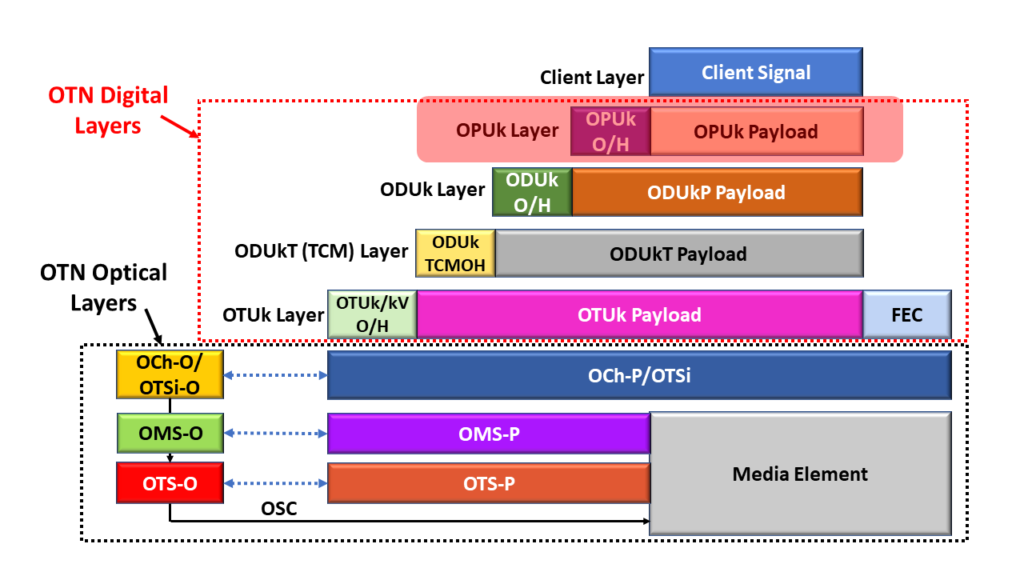
Figure 1, Illustration of the OTN Protocol Stack, with the OPU Layer Highlighted
This figure shows that the OPU Layer is the closest layer to the Client Layer. We map the client data into OPU frames and transport them throughout the OTN.
The Basic Structure of the OPU Frame
I present an illustration of the Basic (or Generic) Structure of the OPU Frame below in Figure 2.
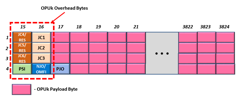
Figure 2, Illustration of the Basic (or Generic) Structure of an OPU Frame
Each OPU frame is a 4 Row x 3810 byte-column structure. The OPU Frame consists of two basic types of fields.
- The Payload Fields (which are the Pink-colored fields in Figure 2), and
- The Overhead Fields (those non-Pink-colored fields on the left-hand side of the figure).
Each OPU frame contains 8 overhead bytes. And all OPU rates (except for the OPU4 frame) include 15,232 payload bytes. OPU4 frames have 15,200 payload bytes, as I show later in this post.
We use the Payload Fields to transport the client data and the Overhead fields for management purposes.
What Do the OPU Overhead Fields Manage?
In general, the OPU Overhead Fields (that I show in Figure 2) manage the following tasks.
- They manage the mapping of client data into the OPU payload, and
- These fields also (in turn) manage the de-mapping of client data from the OPU payload.
- The JC1 – JC6, NJO, and PJO bytes support this effort.
- They identify (to the OTN) the type of client signal that we are transporting via this particular OPUk signal.
- The PSI byte supports this role.
- And finally, they support mapping Lower-Speed ODUj Tributary signals into an OPU4 frame (in particular).
- The OMFI byte supports this role.
What are some of the Various Types of OPU Frames
Throughout this training, we will be working with the following four types of OPU frames.
- The BMP (Bit Synchronous Mapping Procedure) frame.
- The AMP (Asynchronous Mapping Procedure) Applications
- The GMP (Generic Mapping Procedure) Applications – up to OPU3 Rates
- The GMP (Generic Mapping Procedure) Applications – for the OPU4 Rate
Let’s Discuss Each of these Types of OPU Frames below.
OPU Frames for BMP Applications
Figure 3 presents an illustration of an OPU Frame that supports BMP Mapping.
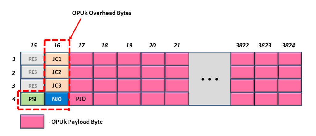
Figure 3, Illustration of an OPU Frame – supporting BMP Mapping
This is by far the simplest OPU frame.
In this particular OPU frame, the JC1 through JC3 and the NJO bytes serve no real purpose other than to occupy space. Additionally, the PJO byte will always transport client data for BMP Mapping applications.
The PSI (Payload Structure Identifier) byte will repeatedly transmit the PSI Message. We will discuss the PSI Message later in this blog post.
Click Here to learn more about the Bit Synchronous Mapping Procedure (BMP) in Lesson 4.
OPU Frames for AMP Applications
Figure 4 illustrates an OPU frame that supports AMP Mapping Applications.
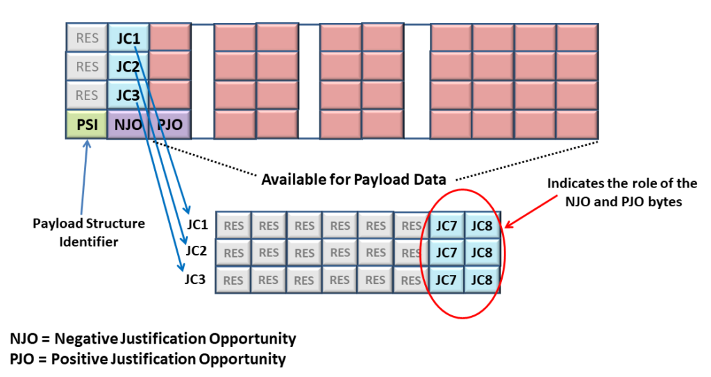
Figure 4, Illustration of an OPU Frame – supporting AMP Mapping Applications
The OPU Frame in Figure 4 looks (and is) very similar to that for Figure 3. However, in the case of Figure 4, the JC1 through JC3, NJO, and PJO bytes are all active and play a significant role in AMP Mapping (or De-Mapping).
Please Click Here to learn more about AMP Mapping and these overhead fields in Lesson 4.
OPU Frames for GMP Applications – up to OPU3
Figure 5 presents an illustration of an OPU Frame that supports GMP Mapping. In this frame, we are looking at a figure that supports OPU rates from OPU0 up to OPU3.
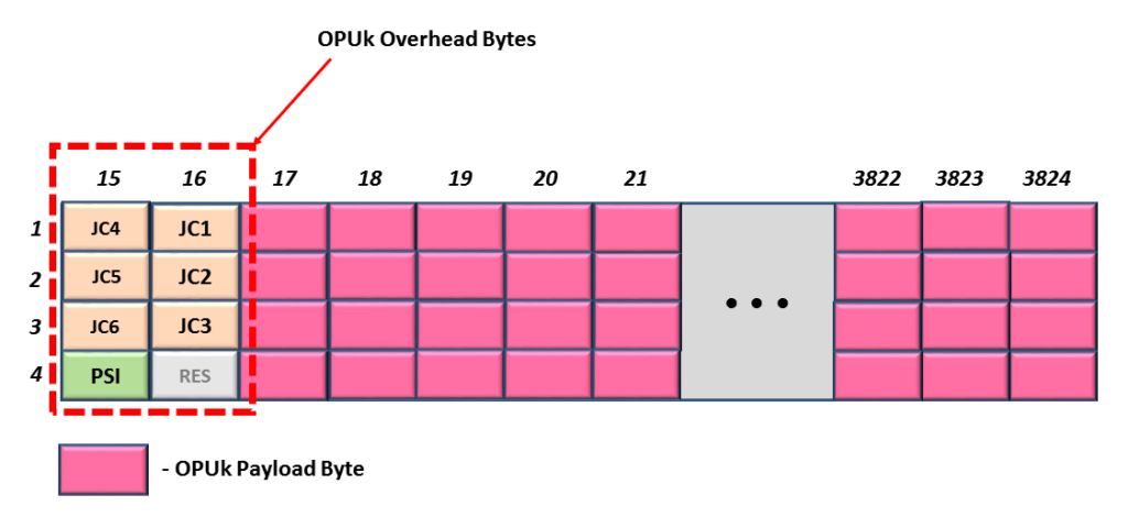
Figure 5, Illustration of an OPU Frame – supporting GMP Mapping Applications (OPU0, OPU1, OPU2, OPU3, and OPUflex).
As you can see, the OPU Overhead for this frame looks VERY different from that of Figures 3 and 4. AMP and BMP Mapping are closely related to each other. However, GMP is a VERY different mapping procedure from AMP or BMP.
Hence, GMP Mapping will require using 6 Justification Control fields (JC1 through JC6). Additionally, GMP does not use the NJO or PJO fields.
Finally, this brings us to the next (and final) type of OPU Frame.
OPU Frames for GMP Applications – OPU4 Applications
Figure 6 presents an illustration of an OPU Frame that also supports GMP Mapping applications. However, this particular figure is only applicable to the OPU4 Rate.
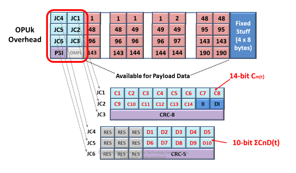
Figure 6, Illustration of an OPU Frame – supporting GMP Mapping Applications (OPU4 ONLY)
The OPU Frame in Figure 6 looks very similar to that in Figure 5, with just two differences.
- The OPU4 Frame has an OFMI byte-field in the OPU Overhead in Row 4, and
- The OPU4 Frame has a total of 32-byte area reserved for Fixed Stuffing.
Both OPU Frames in Figures 5 and 6 have six (6) sets of Justification Control Bytes (JC1 through JC6). These Justification Control fields are required to support GMP Mapping.
How is the OPU4 Frame different from the other OPU Frames?
Each OPU frame I show in Figures 3, 4, and 5 has 15,232 bytes within their OPU Payload.
However, because the OPU4 frame has this 32-byte Fixed Stuff area (at the back-end of this frame), it only has 15,200 bytes within its OPU Payload.
I show a different illustration of the OPU4 frame, in which the OMFI is more visible, below in Figure 7.

Figure 7, Another Illustration of the OPU4 Frame
Click Here to learn more about GMP Mapping in Lesson 4.
The OMFI (Optical Multi-Frame Identifier) byte field only exists in OPU4 Frames. Additionally, we only use the OMFI field when supporting Multiplexed Applications. We will never use the OMFI field if we are just (for example) mapping a 100GBASE-R client signal into an OPU4 payload.
For example, we will use the OMFI field if we are mapping 80 ODU0 signals into an OPU4/ODU4 server signal.
Click HERE to learn more about Multiplexed Applications (e.g., Mapping Lower-Speed ODUj Tributary Signals into a Higher-Speed ODUk Server signal) in Lesson 5.
The PSI Byte and the Payload Structure Identifier Message
Let’s talk about the PSI Byte-field.
In Figure 8, I illustrate our Generic OPU Frame with the PSI Byte-field Highlighted.
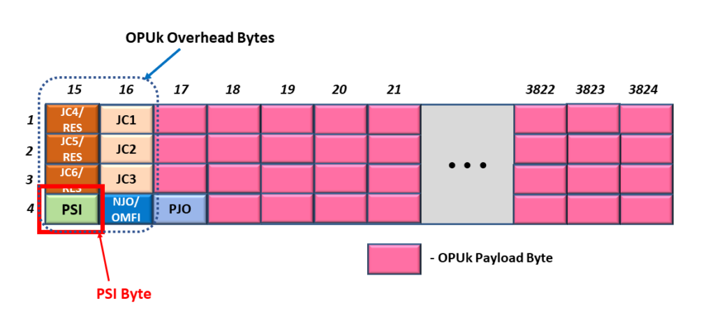
Figure 8, Illustration of the Generic OPU Frame, with the PSI Byte-field Highlighted.
This figure shows that the PSI byte is located in Row 4, Byte-Column 15, within the OPU frame.
The purpose of the PSI byte is to transport the PSI Message repeatedly.
What is the PSI Message?
The PSI (or Payload Structure Identifier) Message is a 256-byte message that identifies the kind of traffic we are transporting via this particular OPU data stream.
ITU-T G.709 defines two different types of PSI Messages.
- The Non-OTN Client/Non-Multiplexed Structure PSI Message and
- The Multiplexed Structure – PSI Message
Figure 9 presents an illustration of an OPU Frame, with the PSI Byte Highlighted, along with a breakout of the Non-OTN Client/Non-Multiplexed Structure PSI Message.
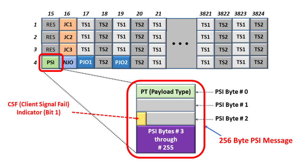
Figure 9, Illustration of the OPU Frame, with the PSI Byte-field highlighted and a breakout of the Non-OTN Client/Non-Multiplexed Structure PSI Message.
Likewise, Figure 10 presents an illustration of an OPU Frame, with the PSI Byte Highlighted, along with a breakout of the Multiplexed Structure PSI Message.

Figure 10, Illustration of the OPU Frame, with the PSI Byte-field highlighted and a breakout of the Multiplexed Structure PSI Message.
What is the Non-OTN Client/Non-Multiplexed Structure PSI Message?
The Non-OTN Client/Non-Multiplexed Structure PSI Message is one variation of a PSI Message. This message is 256 bytes in length (just like its Multiplexed Structure counterpart).
We use this type of PSI Message when working with an OPU frame that is transporting a Single Non-OTN Client Signal (such as 1000BASE-X or 100GBASE-R).
The easiest way to tell if you are working with the Non-OTN Client/Non-Multiplexed PSI Message is if you see the CSF (Client Signal Fail) Bit-field within PSI byte 2.
What is the Multiplexed Structure PSI Message?
The Multiplexed Structure PSI Message is the other variant of a PSI Message.
We use this type of PSI Message when working with an OPU Frame transporting numerous Lower-Speed ODUj Tributary Signals.
The easiest way to tell if you are working with the Multiplexed Structure PSI Message is to see if you do NOT see the CSF (Client Signal Fail) Bit-field within PSI Byte 2.
How Do We Transport the PSI Message?
Since an OPU frame only contains a single PSI Byte, each PSI Message (whether it is the Non-OTN Client/Non-Multiplexed or the Multiplexed-Structure type) is 256 bytes; we have to transport each PSI Message over a stream of 256 consecutive OPU frames.
The Source PTE will continuously transmit the relevant PSI Message over and over.
Again, this PSI Message aims to inform the OTN of the type of client data we are transporting within this particular OPU data stream.
What is the PT (or Payload Type) Byte?
If you take a close look at the PSI Messages within both figures 9 and 10, then you notice that the very first byte within each of these PSI Messages is the PT (or the Payload Type) byte.
The Payload Type byte is key to helping us identify the type of traffic that we are transporting via this OPU data stream.
Table 1 lists the many standard values for PT and the corresponding traffic we are transporting within our OPU data stream.
Table 1, Listing of the Many ITU-T G.709 Standard Values of PT (Payload Type) and the Corresponding Client Signal(s) we are transporting within our OPU data stream.
| Payload Type Value (Hex) | Interpretation (Client Data Type) |
|---|---|
| 01 | Experimental Mapping (Note 3) |
| 02 | Asynchronous CBR Mapping, see Clause 17.2 |
| 03 | Bit-Synchronous CBR Mapping, See Clause 17.2 |
| 04 | Not Available (Note 2) |
| 05 | GFP Mapping, See clause 17.4 |
| 06 | Not Available (Note 2) |
| 07 | PCS Codeword Transparent Ethernet Mapping: 1000BASE-X into OPU0, see Clause 17.7.1 and 17.7.1.1 40GBASE-R into OPU3, see Clauses 17.7.4 and 17.7.4.1 100GBASE-R into OPU4, see Clauses 17.7.5 and 17.7.5.1 |
| 08 | FC-1200 into OPU2e mapping, see Clause 17.8.2 |
| 09 | GFP Mapping into Extended OPU2 Payload, see Clause 17.4.1 (Note 5) |
| 0A | STM-1 Mapping into OPU0, see Clause 17.7.1 |
| 0B | STM-4 Mapping into OPU0, see Clause 17.7.1 |
| 0C | FC-100 Mapping into OPU0, see Clause 17.7.1 |
| 0D | FC-200 Mapping into OPU1, see Clause 17.7.2 |
| 0E | FC-400 Mapping into OPUflex, see Clause 17.9 |
| 0F | FC-800 Mapping into OPUflex, see Clause 17.9 |
| 10 | Bit stream with Octet timing mapping, see Clause 17.6.1 |
| 11 | Bit stream without octet timing mapping, see Clause 17.6.2 |
| 12 | IB SDR mapping into OPUflex, see clause 17.9 |
| 13 | IB DDR mapping into OPUflex, see clause 17.9 |
| 14 | IB QDR mapping into OPUflex, see Clause 17.9 |
| 15 | SDI mapping into OPU0, see Clause 17.7.1 |
| 16 | (I.485/1.001) Gbit/s SDI mapping into OPU1, see Clause 17.7.2 |
| 17 | 1.485 Gbit/s SDK mapping into OPU1, see Clause 17.7.2 |
| 18 | (2.970/1.001) Gbit/s SDI mapping into OPUflex, see clause 17.9 |
| 19 | 2.970 Gbit/s SDI mapping into OPUflex, see Clause 17.9 |
| 1A | SBCON/ESCON mapping into OPU0, see clause 17.7.1 |
| 1B | DVB_ASI mapping into OPU0, see clause 17.7.1 |
| 1C | FC-1600 mapping into OPUflex, see Clause 17.9 |
| 1D | FlexE Client mapping into OPUflex, see Clause 17.11 |
| 1E | FlexE aware (partial rate) mapping into OPUflex, see Clause 17.12 |
| 1F | FC-3200 Mapping into OPUflex, see Clause 17.9 |
| 20 | ODU Multiplex Structure supporting ODTUjk only, see Clause 19 (AMP only) |
| 21 | ODU Multiplex Structure supporting ODTUk.ts or ODTUk.ts and ODTUjk, see Clause (GMP capable) (Note 6) |
| 22 | ODU Multiplex Structure supporting ODTUCn.ts, see Clause 20 (GMP capable) |
| 30 | 25GBASE-R mapping into OPUflex, see Clause 17.13 |
| 31 | 200GBASE-R mapping into OPUflex, see Clause 17.13 |
| 32 | 400GBASE-R Mapping into OPUflex, see Clause 17.13 |
| 55 | Not Available (Note 2) |
| 66 | Not Available (Note 2) |
| 80 - 80F | Reserved Codes for Proprietary Use (Note 4) |
| FD | NULL Test Signal Mapping, see Clause 17.5.1 |
| FE | PRBS Test Signal Mapping, see Clause 17.5.2 |
| FF | Not Available (Note 2) |
NOTES from Table 1
- There are 198 spare codes left for future international standardization. Refer to Annex A of ITU-T G.806 for the procedure to obtain one of these codes for a new Payload Type.
- These values are excluded from the set of available code points. These bit patterns are present in ODUk maintenance signals or were used to represent client types that are no longer supported.
- The value “01” is only used for experimental activities in cases where a mapping code is not defined in this table. Refer to Annex A of ITU-T G.806 for more information on the use of this code.
- These 16 code values will not be subject to further standardization. Refer to Annex A of ITU-T G.806 for more information on the use of these codes.
- Supplement 43 (2008) to the ITU-T G-series of Recommendations indicated that this mapping was recommended using PT = 0x87.
- Equipment supporting ODTUk.ts for OPU2 or OPU3 must be backward compatible with equipment that supports only the ODTUjk. ODTUk.ts capable equipment transmitting PT = 0x21 which receive PT = 0x20 from the far-end shall revert to PT = 0x20 and operate in ODTUjk only mode. Refer to ITU-T G.798 for the specification.
As you can see from Table 1, if we receive an OPU4 signal in which the Payload Type (PT) = 0x07, then this means that this OPU4 signal is transporting a 100GBASE-R client signal. This is one example of how the PSI Message (which contains the PT byte) will inform us of the type of client signal(s) that are transporting via this OPU signal.
We will discuss OPU traffic, in which PT = 0x20 and 0x21 extensively in Lesson 5.
What is the CSF (Client Signal Fail) Bit-field?
As client circuitry (such as an Ethernet MAC) maps its traffic into an OTN signal (such as an OPU4 data-stream), it is expected to monitor the quality of the client signal it provides to the OPU Mapper.
If this client circuitry determines that there is a problem with the data (that it is providing to the OPU Mapper), then it is expected to assert the CSF (Client Signal Fail) bit-field.
The CSF bit-field will travel throughout the OTN (via the PSI Message, within the OPU data stream). This bit-field aims to alert the client circuitry (at the remote PTE) that the underlying client signal is corrupted or defective. In other words, CSF is a caution signal.
It’s like the Biohazard Sign I show in the Figure below.

Figure 11, A Warning Sign – Similar (in the role) to the CSF (Client Signal Fail) Bit-field.
You Can Also Check Out the OPU Training Video Below.
Click on the Link Below to See the ODU Training Video
Click on the Link Below to Return to the Main Lesson 2 Page.
For More Information/Resources about Lesson 2, Click on the Items Below.

The Forum Page


