This blog post presents a video that shows how to implement APS (Automati Protection Switching) both with and without using an APS Communication Protocol.
Lesson 12 – Video 8 – Detailed Discussion of APS without and with the APS Communication Protocol – Video 1
This blog post describes how we can implement APS (Automatic Protection Switching) without using an APS Communication Protocol. Afterward, this blog introduces how to implement APS using the APS Communication Protocol. This video serves as the first of several videos on this topic.
In particular, this video will discuss the following topics:
Executing APS without using the APS Communication Protocol
Under what conditions can we implement APS without using an APS Communication Protocol?
Why can we implement APS (without an APS protocol) in this case?
When not supporting an APS Communication Protocol, the Architecture/Design of the Protection-Switching Controllers.
How to implement Automatic Protection Switching – without implementing an APS Communication Protocol.
Executing APS with an APS Communication Protocol
Under what conditions must we implement APS with an APS Communication Protocol?
Why do we need to use an APS Communication Protocol for these cases?
How to implement Automatic Protection Switching – while using an APS Communication Protocol
Introduction to the APS/PCC Field for OTN/Linear Protection Switching Applications (per ITU-T G.873.1).
The Architecture/Design of the Protection-Switching Controllers – 1+1 Protection Architecture
The Architecture/Design of the Protection Switching Controllers – 1:N Protection Architecture
The NR (No Request) Command
To Learn How to Implement APS, with and without an APS Communication Protocol, Check Out the Video Below.
This blog post breifly defines the pF_DS (Far-End Defect Second) Performance Monitoring paramteter that the OTN PTE will compute and generate.
This blog post aims to briefly define and describe the pF_DS (Far-End Defect Second) Performance Monitoring parameter that the OTN PTE (or ODUk_TT_Sk Atomic Function) will compute and generate.
The OTN PTE (or ODUk_TT_Sk function) will include information on pF_DS without each Performance Monitoring report that it sends to System Management.
NOTES:
The OTN STE (OTUk_TT_Sk Atomic Function) also monitors and generates information on the pF_DS (Far-End Defect Second) parameter at the OTUk Layer. Please see the pF_DS at OTUk Layer Post for more details on this parameter.
Throughout this post, I will use the terms: OTN PTE and ODUk_TT_Sk Function interchangeably. In the context of this blog post, these two terms mean the same thing.
Introduction
At the ODUk Layer, the OTN (Sink) PTE is the entity that is responsible for detecting and reporting Far-End Defect Second events.
As the OTN PTE receives and monitors its incoming ODUk signal, it will check for many things. It will continuously check for the incoming ODUk signal for Service-Affecting Defect (e.g., dAIS, dOCI, dLCK, dTIM, etc.) as well as bit (or symbol) errors (e.g., PM-BIP-8 errors and PM-BEI errors).
Another thing that the OTN PTE will do (as it continuously monitors its incoming ODUk signal) is to divide each second of (monitoring) time into the following two categories:
Far-End Available (Working) Seconds, and
Far-End Defect Seconds
Anytime the OTN PTE detects and categorizes a given one-second period as being a Far-End Defect Second, it will increment the pF_DS parameter and report that information to System Management.
New Comprehensive OTN Training…. Available Now. Click on the Banner Below to Learn More!!
Discounts Available for a Short Term!!
So When does the OTN PTE detect and flag a given One-Second Period as being a “Far-End Defect Second”?
ITU-T G.798 presents the following Performance Monitoring Equation for the ODUk_TT_Sk function.
pF_DS <- dBDI
Where:
dBDI is the current state of the ODUk-BDI or the Backward Defect Indicator Defect (at the ODUk Layer).
The OTN PTE (or ODUk_TT_Sk function) will continuously evaluate the above equation as it monitors its incoming ODUk signal.
This equation states that the OTN PTE will declare a given one-second period as being a Far-End Defect Second if it has declared the dBDI defect condition during any portion of that one second.
A given OTN PTE will declare a one-second period as a Far-End Defect Second if the remote OTN PTE declares any of the following defect conditions:
dAIS (ODU-AIS)
dOCI
dLCK
dTIM
In this case, the OTN PTE will increment the pF_DS parameter for each one-second period it categorizes as a Far-End Defect Second.
Conversely, the OTN PTE will declare a one-second period as an Available Second if the remote OTN PTE is not declaring any of the defects mentioned above. The OTN PTE will NOT increment the pF_DS parameter in this case.
What Does This Mean in English?
Of course, if the OTN PTE declares the dBDI defect condition, then this also means that the remote PTE is declaring a service-affecting defect condition. In other words, the pF_DS parameter reflects the health of the remote (or Far-End) terminal.
If the remote terminal declares no service-affecting defects, the near-end terminal will not increment the pF_DS parameter. On the other hand, if the remote terminal declares a service-affecting defect, then the near-end terminal will increment the pF_DS parameter.
So, if the ODUk_TT_Sk function has declared the dBDI defect condition for even a fraction of a given one-second period, it will declare it as a Far-End Defect Second. It will also set the parameter pF_DS to 1 and report that information to System Management.
Conversely, if the OTN PTE determines that the ODUk_TT_Sk function did not declare the dBDI defect condition at all during a given one-second period. In that case, it will declare that one-second period is a Far-End Available (Working) Second. In this case, the OTN STE will NOT set the parameter pF_DS to 1.
Hence the pF_DS parameter reflects the network’s health at the remote terminal (e.g., the other end of the ODUk Path).
Is there such a thing as a Near-End Defect Second?
Throughout this post, we have used the term: Far-End Defect Second. Does this mean that there is another parameter called Near-End Defect Second?
Answer: Yes, there is such a parameter. See the Near-End Defect Seconds (pN_DS) post at the ODUk Layer for more details.
Clueless about OTN? We Can Help!! Click on the Banner Below to Learn More.
Discounts Available for a Short Time!!
And Finally, Click on the Image Below to see More OTN-Related Topics in this Blog.
This blog post introduces the concept of SNCP (Subnetwork Circuit Protection) Switching. This post also briefling introduction SNCP Monitoring schemes such as SNC/I, CL-SNCG/I, SNC/Ne, SNC/Ns and SNC/S.
Lesson 12 – Video 3 – Introduction to SNCP (Subnetwork Circuit Protection) Switching
This blog post contains a video that covers the introductory part of Subnetwork Circuit Protection switching.
In particular, this video will discuss the following topics:
Introduction to the concept of Subnetwork Circuit Protection (SNCP)-Switching
How is SNCP different from Trail Protection Switching
Why does the Industry prefer SNCP Monitoring/Switching instead of Trail Protection Monitoring/Switching?
Introduction to the following forms of SNCP Monitoring:
SNC/I – Subnetwork Circuit/Inherent Monitoring
CL-SNCG/I – Compound Link – Subnetwork Circuit Group/Inherent Monitoring
We will cover each of these monitoring forms (for Protection-Switching purposes), in much greater detail, throughout the remaining videos in Lesson 12.
In particular, we will cover these forms of SNCP Monitoring (in detail) in the following videos.
This blog post presents the fourth and final video of the ODUT_TT_Sk Atomic Function. This video discusses how the ODUT_TT_Sk function supports Performance Monitoring at TCM Level i.
Lesson 11 – Video 6 – Tandem Connection Monitoring – ODUT_TT_Sk Atomic Function, Part FOUR
This blog post contains a video that covers the fourth part of the Sink Direction Tandem Connection Monitoring (TCM) related Atomic Functions.
In particular, this video covers the fourth part of the ODUT_TT_Sk Atomic Function.
More specifically, this video covers the following Performance Monitoring parameters that the ODUT_TT_Sk Atomic Function generates.
TCMi-pN_DS (TCM Level i, Near-End Defect Seconds)
TCMi-pF_DS (TCM Level i, Far-End Defect Seconds)
TCMi-pN_EBC (TCM Level i, Near-End Error-Block Count)
TCMi-pF_EBC (TCM Level i, Far-End Error-Block Count)
pN_delay – TCM Level i, Round-Trip Subnetwork Delay
This video also briefly describes the functionality of the ODUT_TT_Sk Atomic Function whenever it has been configured to operate in both the:
Monitor Mode, and
Transparent Mode
This video completes our discussion of the ODUT_TT_Sk Atomic Function.
This post presents the 5th of the 7 Videos that covers training on the Peformance Monitoring of the ODUk Layer (for Non-Multiplexed Applications). This post focuses on the Sink Direction ODU-Layer Atomic Functions. More specifically, this post presents a video that discusses how the ODUk_TT_Sk Atomic Function declares and clears the PM-dDEG defect condition.
OTN – Lesson 10 – Video 5N – The ODUk_TT_Sk Atomic Function
This blog post presents a video that continues our discussion of the ODUk_TT_Sk Atomic Function.
This video covers the following features within the ODUk_TT_Sk Atomic Function.
How the ODUk_TT_Sk function declares and clears the dDEG (Path Signal Degrade) defect condition?
What does the ODUk_TT_Sk function do with its AI_TSF Output pin whenever it declares a Service-Affecting defect condition?
What does the ODUk_TT_Sk function do with its AI_TSD Output pin whenever it declares the dDEG (Signal Degrade) defect condition?
This post presents the 9th of the 11 Videos that covers training on Performance Monitoring at the OTUk Layer. This post focuses on the Sink Direction OTU-Layer Atomic Functions.
OTN – Lesson 9 – Video 9 – OTU Layer Sink Direction Circuitry/Functionality – Part 7
This blog post contains a video that concludes our discussion of the OTUk_TT_Sk Atomic Function.
In particular, this video discusses the following aspects of the OTUk_TT_Sk Function.
Defect Correlation Equations/Analysis
Consequent Equations/Analysis
Performance Monitoring Equations/Analysis
Finally, this video summarizes and wraps up the training/discussion of the OTUk_TT_Sk Atomic Function.
This post presents the 5th of 11 Videos that covers training on Performance Monitoring at the OTU Layer. This post focuses on the Sink Direction OTU-Layer Atomic Functions.
OTN – Lesson 9 – Video 5 – OTU Layer Sink Direction Circuitry/Functionality – Part 3
This blog post contains another video that focuses on (and wraps up our discussion on) the OTSiG/OTUk_A_Sk Atomic Function.
This Video serves as Part 3 within our Sink (or Receive) Direction Analysis of OTU-Layer Atomic functions. This Video is also the 5th of 11 videos within Lesson 9.
We start this Video by reviewing the complete list of defects that the OTSiG/OTUk_A_Sk function declares and clears. Afterward, I will introduce you to the following:
The concept/purpose of Consequent Equations
A Review (and interpretation) of Consequent Equations for the OTSiG/OTUk_A_Sk Atomic Function.
Introduction to Defect Correlation
A Review of the Defect Correlation Equations for the OTSiG/OTUk_A_Sk Atomic Function.
A Review of the Performance Monitoring Equations for the OTSiG/OTUk_A_Sk Atomic Function.
A Final Summary of the OTSiG/OTUk_A_Sk Atomic Function.
This blog post briefly describes the term pF_EBC (Far-End Errored Block Error).
What is the pF_EBC (Far-End Errored Block Count) Performance Monitoring Parameter for the OTUk Layer?
The purpose of this blog post is to briefly define and describe the pF_EBC (Far-End Errored Block Count) Performance Monitoring parameter that the OTN (Sink) STE (or OTUk_TT_Sk Atomic Function) will compute and tally.
The Sink STE (or OTUk_TT_Sk function) will include information on the pF_EBC parameter within each Performance Monitoring report it sends to System Management.
NOTES:
The OTN PTE (ODUP_TT_Sk Atomic Function) also monitors and generates information on the pF_EBC (Far-End Errored Block Count) parameter at the ODUk Layer. Please see the pF_EBC at ODUk Layer Post for more details on this parameter.
Throughout this post, I will use the terms: OTN STE and OTUk_TT_Sk Function interchangeably. In the context of this blog post, these two terms mean the same thing.
Introduction
At the OTUk Layer, the OTN (Sink) STE is the entity that is responsible for detecting and reporting Far-End Errored Block Counts (or SM-BEI errors).
As the Sink STE receives and monitors its incoming OTUk signal, it will check for many things. It will continuously scan the incoming OTUk signal for bit (or symbol) errors (e.g., SM-BIP-8, FEC, etc.). It will also check for Service-Affecting defects (e.g., dTIM, dLOM, dLOF, dAIS, dLOS-P, etc.).
New Comprehensive OTN Training…Available Now. Click on the Banner Below to Learn More!!!
Discounts Available for a Short Time!!!
Definition of Terms:
Before we proceed, we need to define the following terms for this blog post:
Block: In this case, we define a block as an OTUk frame.
Far-End Errored Block: In this blog post, we define a far-end errored block as any OTUk frame that contains a value for the SM-BEI count that ranges anywhere between 1 and 8. Anytime the OTN STE receives a block with an SM-BEI count value of 0x0, we consider that block to be un-erred.
As the Sink STE checks the incoming OTUk signal for errors and defects, it will also record the total number of far-end errored blocks it detects for each one-second period.
At the end of a given one-second period, the Sink STE will load the total number of far-end errored block counts (detected in the most recent one-second period) into the variable pF_EBC.
The Sink STE will then report this value for pF_EBC to System Management as a part of its Performance Monitoring report.
Table 1 presents the number of blocks/second that each type of OTUk signal will transport for each value of k.
Table 1, Number of Blocks/Second for each OTUk Rate.
OTUk Type
Number of Blocks/Second
OTU1
20,421
OTU2
82,026
OTU3
329,492
OTU4
856,388
OTUCn
n x 860,177
So How does the OTN STE tally Errored Blocks for the pF_EBC parameter?
As the Sink STE receives and monitors its OTUk signal, it will continually check the SM-BEI counts within each incoming OTUk frame (or block).
Anytime the Sink STE receives an OTUk frame in which the SM-BEI value is anywhere from 1 to 8, it will increment its internal (pF_EBC Counter) by 1.
NOTE: This means that even if the Sink STE receives an SM-BEI value of “8”, it will still just increment its pF_EBC Counter by 1 (not 8).
Conversely, the Sink STE will not increment its internal pF_EBC Counter whenever it receives an OTUk frame (or block) that contains an SM-BEI value of 0, or 9 through 15. The Sink STE consider these type of OTUk frames to be un-erred.
At the end of each one-second period, the Sink STE will load the contents of this internal counter into the pF_EBC parameter. The Sink STE will then include that information within its Performance Monitor report that it sends to System Management.
Are there any Times or Conditions during which the Sink STE will NOT tally Errored Block Counts for the pF_EBC parameter?
ITU-T G.798 states that the OTUk_TT_Sk function will stop tallying Errored Blocks for the pF_EBC parameter whenever the upstream circuitry (e.g., the OTSi/OTUk_A_Sk or OTSiG/OTUk_A_Sk Atomic Function) asserts the CI_SSF input of the OTUk_TT_Sk function.
In other words, the Sink STE will not tally any Errored Block Counts (for the pF_EBC parameter) whenever it (e.g., the OTSi/OTUk_A_Sk or OTSiG/OTUk_A_Sk functions) declare any of the following service-affecting defect conditions.
Is there such a thing as Near-End Errored Block Counts?
Throughout this post, we have used the term Far-End Errored Block Count. Does this mean that there is another parameter called Near-End Errored Block Count?
This post briefly defines the SM-BEI (Section Monitoring – Backward Error Indicator) parameter. It also describes how an OTN Network will transmit the SM-BEI parameter from one Network Element to another.
What is the OTUk-BEI (Backward Error Indicator) or SM-BEI Parameter?
The purpose of this post is to define the SM-BEI (Section Monitor – Backward Error Indicator) parameter that a Source STE will generate, and a Sink STE will tally at the OTUk-Layer.
Introduction
In another post, we describe how the Sink STE (OTUk_TT_Sk function) will compute and verify the SM-BIP-8 value within each incoming OTUk frame.
NOTE: I will use the terms Sink STE and OTUk_TT_Sk function interchangeably throughout this post.
The Sink STE performs this task to check for any occurrences of bit errors during data transmission (over optical fiber) from the STE Source Terminal to the STE Sink Terminal.
However, just as the Sink STE (through its near-end Source STE) sends the SM-BDI indicator back out to the remote Terminal whenever it declares a service-affecting defect. The Sink STE (again, through its near-end Source STE) will also send out information to the remote Terminal to reflect the number of BIP-8 errors detected within each incoming OTUk frame.
We call this information the Backward-Error Indicator (or BEI). I will explain how we generate and transport this parameter below.
A High-Level Overview of the SM-BEI Parameter and How we Use it.
Before we get into the details of how things work with the various Atomic Functions and Ports, let’s spend some time discussing the underlying philosophy for transmitting the SM-BEI indicator.
Let us consider two Network Elements. We will call one Network Element, N.E East, and the other Network Element N.E. West. We have connected these two networks via a Bidirectional Optical Connection, as shown below in Figure 1.
Figure 1, Illustration of Network Elements East and West connected over a Bidirectional Fiber Optic Connection.
Now let’s consider two possible cases when dealing with SM-BIP-8 errors and SM-BEI.
The Unerred Case (where the Number of BIP-8 Errors = 0) and
The Erred Case (where the Number of BIP-8 Errors = 5)
The Unerred Case (where the Number of BIP-8 Errors = 0)
Let’s assume that the OTUk Transceiver and OTUk Framer (within Network Element EAST) are not detecting any BIP-8 errors within a given OTUk frame.
We show this case below in Figure 2.
Figure 2, Illustration of Network Element EAST detecting NO BIP-8 Errors within OTUk frame # n
Please note that in Figure 2, I show that both the OTUk Transceiver and OTUk Framer blocks (within Network Element EAST)are detecting ZERO BIP-8 errors. I show this because many OTUk Transceivers will also include some OTUk Framing capability and can detect and flag BIP-8 errors.
In this case, Network Element EAST will respond to this ZERO BIP-8 Error condition by setting the BEI field (within its next outbound OTUk frame – back to Network Element WEST) to “0x00”.
Why “0000”?
Because that’s the Number of BIP-8 Errors that the OTUk Transceivers/Framer blocks have detected in their most recently received OTU frames.
Figure 3 shows Network Element EAST setting the BEI field to 0x00 within its next outbound OTUk frame.
Figure 3, Illustration of Network Element EAST responding to the NO BIP-8 Error Condition by setting BEI = 0 within its next outbound OTUk frame.
Both the OTUk Transceiver and Framer (within Network Element WEST) will receive this OTUk frame (with BEI = 0), and it will “know” the quality of its OTUk signal (out to Network Element EAST) is GOOD.
Therefore, the BEI field (within the OTUk Overhead) gives a Network Element a way to provide feedback to an upstream Network Element about the quality of its output signal.
As long as Network Element WEST receives OTUk frames with the BEI field set to 0, it has some indication that it is transmitting a good quality OTUk signal out to Network Element EAST.
NOTE: Since this is a bidirectional connection between Network Elements EAST and WEST, then Network Element WEST can (and will) provide the same type of feedback to Network Element EAST.
Now let’s move on to the Erred Case.
The Erred Case (where the Number of BIP-8 Errors = 5)
Now that we have covered the No-Error condition let’s cover a different situation. Let us assume that Network Element EAST has just received an OTUk frame, which detects 5 BIP-8 errors.
I show an illustration of this condition below in Figure 4.
Figure 4, Illustration of Network Element EAST detecting 5 BIP-8 Errors within OTUk Frame # n
In this case, Network Element EAST will respond to this error condition by setting the BEI field (within its very next outbound OTUk frame – back out to Network Element WEST) to “0x05” (e.g., the same number of BIP-8 errors that it detected) within its recently received OTUk frame.
Why “0x05”?
Because that’s the number of BIP-8 bit errors that Network Element EAST has detected within its most recently received OTUk frame.
Figure 5 shows Network Element EAST setting the BEI field to 0x05 within its next OTUk frame.
Figure 5, Illustration of Network Element EAST responding to the 5 BIP-8 Error Condition by setting BEI = 5 within its next outbound OTUk frame
In this case, since Network Element EAST sets the BEI-field to “0x05”, it is giving Network Element WEST some feedback that it (Network Element EAST) is having problems with the OTUk data-stream that it is receiving from Network Element WEST.
Now that we understand the underlying philosophy behind using the SM-BEI fields, let’s discuss the SM-BEI parameter in greater detail.
New Comprehensive OTN Training…Available Now. Click on the Banner Below to Learn More!!
Discounts Available for a Short Time!!!
An In-depth Discussion – How Does the Sink STE generate the BEI Parameter?
In the SM-BIP-8 Post, I mentioned that the Sink STE would locally compute its version of the SM-BIP-8 value based upon the contents within the OPUk portion of the OTUk frame that it has received.
I also mentioned that this SM-BIP-8 value is an 8-bit value.
The Sink STE (or OTUk_TT_Sk function) will then read out the contents of the SM-BIP-8 byte two OTUk frame periods later, and it will compare these two BIP-8 values.
I show the location of the BIP-8 Value, with respect to the OTUk Frame (that we used to compute this value), below in Figure 6.
Figure 6, The Location of the BIP-8 Value, with respect to the OTUk Frame (that we used to compute this value)
Comparing the Locally Computed BIP-8 Value with the Remotely Computed Value
At this point, the Sink PTE will compare its locally-computed SM-BIP-8 value with the remotely-computed SM-BIP-8 value (read out from the SM-BIP-8 byte field – two OTUk frame periods later).
If these byte values (of BIP-8 values) are equal, then we can state that this OTUk frame incurred no bit errors during transmission over the optical fiber.
On the other hand, if these two BIP-8 values are NOT the same, then the Sink STE (or OTUk_TT_Sk function) notes how many bits (between these two BIP-8 values) must be different from each other.
In other words, as the OTUk_TT_Sk function compares its locally computed BIP-8 value and that which it reads in from the BIP-8 byte-field within the incoming OTUk data stream. It will do this by performing a bit-by-bit XOR operation with each of these byte values.
The OTUk_TT_Sk function must then count the numbers of “1s” that occur during this bitwise XOR comparison. The OTUk_TT_Sk function will come up with any of the following nine (9) possible results.
0 bits in Error – Error-Free Transmission
1 bit in Error
2 bits in Error
3 bits in Error
4 bits in Error
5 bits in Error
6 bits in Error
7 bits in Error
8 (all) bits in Error
In Figure 7, I show a draw of a Bit-Wise XOR Comparator that the OTUk_TT_Sk function can use to compare its locally-computed BIP-8 value with the remotely-computed BIP-8 value.
Figure 7, Illustration of a Bit-Wise XOR Comparator that the OTUk_TT_Sk function can use to compare its Locally-Computed BIP-8 Value with the Extracted (Remotely Computed) BIP-8 Value for a given OTUk frame
The OTUk_TT_Sk function will need to send these BIP-8 comparison results back out to the remote terminal (the source of the OTUk signal that we are monitoring) in the form of BEI (Backward-Error-Indicator) value.
How does the OTUk_TT_Sk send out SM-BEI Information to the Remote Terminal?
Once the OTUk_TT_Sk function has performed the comparison (between its locally computed BIP-8 value with the remote-computed value), it then needs to report this information back to the remote terminal.
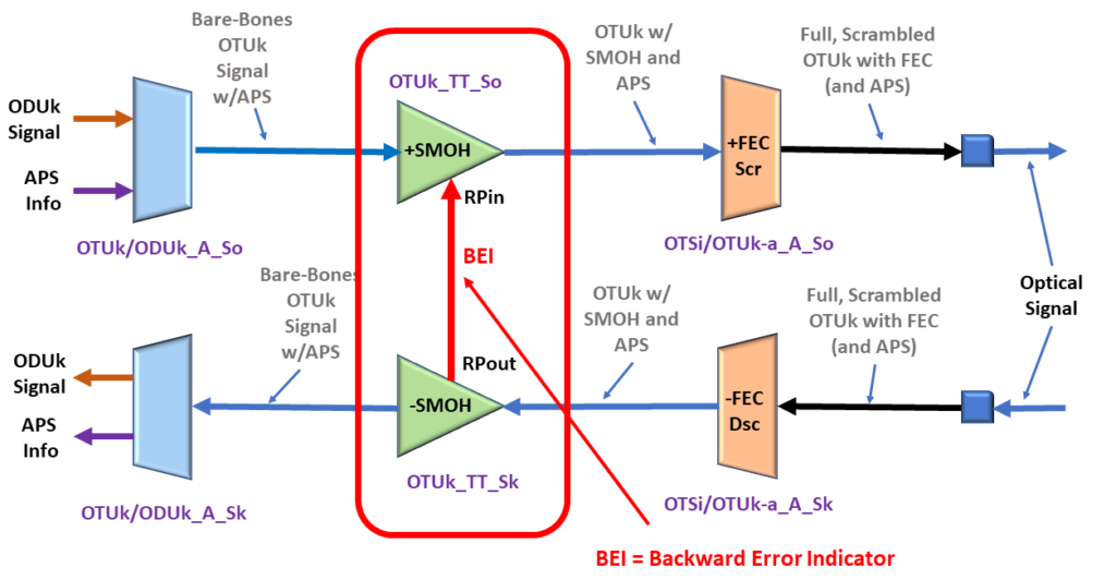
The OTUk_TT_Sk function will send a command to its collocated OTUk_TT_So function via the BEI (or RI_BEI) port.
I show a drawing of the OTUk_TT_Sk function, its collocated OTUk_TT_So function, and the BEI port below in Figure 8.
Figure 8, Illustration of the OTUk_TT_Sk, its collocated OTUk_TT_So function, and the BEI port.
The OTUk_TT_Sk function will use the BEI port to tell the OTUk_TT_So function what value it should set the BEI/BIAE nibble field to during its next outbound OTUk frame.
How does the OTUk Network Element transmit the SM-BEI Indicator?
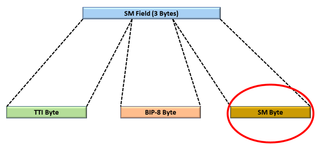
The Network Element will transmit the SM-BEI indicator by setting the BEI/BIAE nibble-field within the SM (Section Monitoring) byte, to the BEI value, within each outbound OTUk frame.
The SM byte resides within the 3-byte SM (Section Monitoring) field of the OTUk Overhead.
Figures 9a, 9b, and 9c present the BEI/BIAE nibble-field location within an OTUk frame. First, Figure 9a shows the location of the SM field within the OTUk Overhead.
Figure 9a, The SM Field within the OTUk Overhead
Second, Figure 9b shows the location of the SM byte within the 3-byte SM Field.
Figure 9b, The Location of the SM-Byte within the SM Field
Finally, Figure 9c presents the BEI/BIAE nibble-field location within the SM-byte.
Figure 9c, The Location of the BEI/BIAE nibble-field within the SM Byte, within the SM Field, of the OTUk Overhead.
What is the Official Interpretation of the SM-BEI/BIAE Nibble within the OTUk Frame?
The SM-BEI/BIAE Nibble does not just carry Backward Error Indication information. It also transports the BIAE (Backward Input Alignment Error Indicator).
Table 1 presents a list that defines how we should interpret each value for the SM-BEI/BIAE Nibble.
SM-BEI/BIAE[1:4] Nibble Value
Is OTUk_TT_Sk Declaring dIAE?
BEI Count (Value) if any
0000
NO
0
0001
NO
1
0010
NO
2
0011
NO
3
0100
NO
4
0101
NO
5
0110
NO
6
0111
NO
7
1000
NO
8
1001, 1010
NO
0
1011
YES (BIAE Indicator)
0
1100 through 1111
NO
0
This table shows that only nibble values of 0x01 through 0x08 reflect some (non-zero) Backward Error Indication count.
Summary
Each Network Element can use the BEI/BIAE Nibble-field within the SM byte to provide the remote Network Element with feedback on the number of SM-BIP-8 bit errors they are detecting.
The remote Network Element will note (and increment the pF_EBC parameter) each time it receives an OTUk frame, in which the SM-BEI/BIAE nibble-field ranges between 1 and 8.
In another post, I discuss the pF_EBC (Far-End – Error Block Count) parameter in greater detail.
Clueless about OTN? We Can Help!! Click on the Banner Below to Learn More!!
Discounts Available for a Short Time!!!
For More Information on OTN Posts in this Blog, click on the Image below.
This blog post briefly describes the Performance-Monitoring parameter or term pN_EBC (Near-End Errored Block Count) for the OTUk-Layer.
What is the pN_EBC (Near-End Errored Block Count) Performance-Monitoring Parameter for the OTUk Layer?
This blog post aims to briefly define and describe the pN_EBC (Near-End Errored Block Count) Performance Monitoring parameter that the Sink STE (or OTUk_TT_Sk Atomic Function) will compute and tally.
The Sink STE (or OTUk_TT_Sk function) will include information on the pN_EBC parameter within each Performance Monitoring report it sends to System Management.
NOTES:
The OTN PTE (or ODUP_TT_Sk Atomic Function) also monitors and generates information on the pN_EBC (Near-End Errored Block Count) parameter at the ODUk Layer. Please see the pN_EBC at ODUk Layer Post for more details on this parameter.
Throughout this post, I will use the terms: Sink STE and OTUk_TT_Sk Function interchangeably. In the context of this blog post, these two terms mean the same thing.
Introduction
At the OTUk Layer, the OTN (Sink) STE is the entity that is responsible for detecting and reporting Near-End Errored Block Counts (or SM-BIP-8 Errors).
NOTE: We refer to SM-BIP-8 errors as Near-End errors because these are errors that the Near-End Sink STE is detecting on its end. In contrast, we refer to the SM-BEI parameter as Far-End errors because that parameter reflects errors that a remote (or Far-End) Sink STE is detecting and reporting.
As the Sink STE receives and monitors its incoming OTUk signal, it will check for many things. It will continuously scan the incoming OTUk signal for bit (or symbol) errors (e.g., SM-BIP-8 errors, FEC errors, etc.) as well as Service-Affecting Defects (e.g., dTIM, dLOF, dLOM, dLOS-P, dAIS, etc.).
Definition of Terms:
Before we proceed, we need to define the following terms for this blog post:
Block: In this case, we define a block as an OTUk frame.
Errored Block: In this blog post, we define an errored block as any OTUk frame (or block) that contains at least one SM-BIP-8 error.
As the Sink STE checks the incoming OTUk signal for errors and defects, it will also keep a count of the number of errored blocks it detects for each one-second period.
At the end of a given one-second period, the Sink STE will load the total number of errored block counts (detected and tallied in the most recent one-second period) into the variable pN_EBC.
Since each type of OTUk signal (for a given value of k) transmits a different number of OTUk frames than does another OTUk signal (with a different value for k), each OTUk type will transmit a different number of blocks/second, as we show below in Table 1.
Table 1, Number of Blocks/Second for each OTUk Rate
OTUk Type
Number of Blocks/Second
OTU1
20,421
OTU2
82,026
OTU3
329,492
OTU4
856,388
OTUCn
n x 860,177
So How does the OTN STE tally Errored Blocks for the pN_EBC parameter?
As the Sink STE receives and monitors its OTUk signal, it will continually check for SM-BIP-8 errors.
Anytime the Sink STE receives an OTUk frame that contains at least one SM-BIP-8 error, then it will increment its internal (pN_EBC Counter) by 1.
Conversely, the Sink STE does not increment its internal pN_EBC Counter whenever it receives an OTUk frame that contains 0 SM-BIP-8 errors.
At the end of each one-second period, the Sink STE will load the contents of this internal counter into the pN_EBC parameter and include that information within its Performance Monitor report that it sends to System Management.
New Comprehensive OTN Training…Available Now. Click on the Banner Below to Learn More!!!
Discounts Available for a Short Time!!!
Are there any Times or Conditions during which the OTN STE will NOT tally Errored Block Counts for the pN_EBC parameter?
Yes, ITU-T G.798 states that the OTUk_TT_Sk function will stop tallying Errored Blocks for the pN_EBC parameter whenever the upstream circuitry (e.g., the OTSi/OTUk_A_Sk or OTSiG/OTUk_A_Sk Atomic function) asserts the CI_SSF input of the OTUk_TT_Sk function.
In other words, the OTN STE will not tally any Errored Block Counts (for the pN_EBC parameter) whenever it (e.g., the OTSi/OTUk_A_Sk or OTSiG/OTUk_A_Sk functions) declares any of the following service-affecting defects conditions.
Is there such a thing as Far-End Errored Block Counts?
Throughout this post, we have used the term Near-End Errored Block Count. Does this mean that there is another parameter called Far-End Errored Block Count?