

What is the dBDI (Backward Defect Indicator) defect at the OTUk Layer?
In short, the dBDI (or Backward Defect Indicator) signal is functionally equivalent to the RDI (Remote Defect Indicator) for OTN applications.
In OTN applications, Network Equipment can declare the dBDI defect at either the OTUk Layer or the ODUk Layer.
This post will discuss the dBDI defect for the OTUk Layer, which we can call the OTUk-BDI defect condition.
We address the dBDI defect for the ODUk Layer in another post.
In another post, I’ve also described the RDI (Remote Defect Indicator) signal or defect in generic terms.
In this post, we are going to describe the following items.
- What conditions will cause an OTUk Network Element to transmit the dBDI indicator to the remote Network Element?
- How does the OTUk Network Element transmit the dBDI indicator to the remote Network Equipment?
- How does the OTUk Network Element receiving the dBDI signal detect and declare the dBDI defect condition?
- And, how does the OTUk Network Element clear the dBDI defect condition?
Has Inflation got You Down? Our Price Discounts Can Help You Beat Inflation and Help You Become an Expert on OTN!!! Click on the Banner Below to Learn More!!
Corporate Discounts Available!!

What conditions will cause an OTUk Network Element to transmit the dBDI indicator?
In Figure 1, we illustrate two Network Elements (consisting of OTUk Framers and OTUk Transceivers) exchanging OTUk traffic over Optical Fiber.
We will call one of these Network Elements NETWORK ELEMENT WEST and the other Network Element, NETWORK ELEMENT EAST.
NETWORK ELEMENT WEST contains the following pieces of hardware
- OTUk Framer West
- OTUk Transceiver East and
- Optical I/F Circuitry (O->E)/(E->O)
Likewise, NETWORK ELEMENT EAST contains the following pieces of hardware.
- OTUk Framer East
- OTUk Transceiver East and
- Optical I/F Circuitry (O -> E)/(E -> O)

Figure 1, Illustration of two Network Elements that are connected over Optical Fiber
A Defect Condition
Now, let us imagine that some impairment occurs in the span of Optical Fiber carrying OTUk traffic from NETWORK ELEMENT WEST to NETWORK ELEMENT EAST.
This impairment will then cause NETWORK ELEMENT EAST to declare a service-affecting defect, as shown in Figure 2.

Figure 2, Illustration of NETWORK ELEMENT EAST declaring a Service-Affecting Defect due to an impairment in Optical Fiber
NETWORK ELEMENT EAST might respond to this defect condition in several ways. It might transmit the ODUk-AIS indicator towards downstream equipment (as a replacement signal).
NETWORK ELEMENT EAST might also invoke Protection Switching (if supported).
Sending the OTUk-BDI Indicator in Response
Finally, NETWORK ELEMENT EAST will also respond to this defect by transmitting the dBDI (or OTUk-BDI) indicator back towards the upstream Network Element (NETWORK ELEMENT WEST, in this case).
Figure 3 shows an illustration of NETWORK ELEMENT EAST, transmitting the OTUk-BDI indicator (back towards NETWORK ELEMENT WEST) in response to it declaring this service-affecting defect.

Figure 3, Illustration of NETWORK ELEMENT EAST responding to the Defect Condition by sending the OTUk-BDI indicator back towards NETWORK ELEMENT WEST
NETWORK ELEMENT EAST sends the OTUk-BDI indicator (back to NETWORK ELEMENT WEST) to alert it of this defect condition (between the two Network Elements).
In other words, NETWORK ELEMENT EAST is saying, “Hey, NETWORK ELEMENT WEST, I’m having problems with the data that you are sending me. I’d just thought that I’d let you know”.
There are many reasons why all of these notifications are useful.
This notification gives the Overall Network a clearer picture of exactly where the problem (or impairment) is.
It can also notify maintenance personnel of these problems and provide them with helpful information before they “roll trucks.”
Clueless about OTN? We Can Help!!! Click on the Banner Below to Learn More!!
Discounts Available for a Short Time!!
So What EXACTLY are those Defects that will cause a Network Element to transmit the OTUk-BDI indicator?
The Network Element will transmit the OTUk-BDI indicator anytime it declares any service-affecting defect conditions.
- dTIM – Trail Trace Identification Mismatch Defect(*)
- dAIS – OTUk-AIS Defect
- dLOF – Loss of Frame Defect
- dLOM – Loss of Multiframe Alignment Defect
- dLOS-P/dLOS-P[i] – Loss of Signal – Payload Defect
- dLOFLANE[j] – Loss of Frame – Lane Signal Defect (OTL3.4 and OTL4.4 Applications)(*)
- dLOL – Loss of Lane Alignment (OTL3.4 and OTL4.4 Applications)(*)
(*) – Must be a member of THE BEST DARN OTN TRAINING PRESENTATION…PERIOD!!! to see this material.
The Network Element will continue to transmit the OTUk-BDI indicator for the duration it declares any of these defects.
Once the Network Element no longer declares these defect conditions, it will stop transmitting the OTUk-BDI indicator.
NOTE: ITU-T G.798 is the standards document that specifies the conditions and set of defects that will cause the Network Element to transmit the OTUk-BDI indicator to the remote terminal.
If you wish to see a detailed analysis of how ITU-T G.798 specifies these requirements, please look at the standards document itself or check out the OTUk-BDI – ITU-T G.798 Analysis post.
How does the OTUk Network Element transmit the dBDI indicator?
The Network Element will send the OTUk-BDI indicator by setting the BDI bit-field (Bit 5) within the SM (Section Monitoring) Byte, to 1, within each outbound OTUk frame.
The SM byte resides within the 3-byte SM (Section Monitoring) field of the OTUk Overhead.
Figures 4a, 4b, and 4c present the location of the BDI field.
Figure 4a presents an illustration of the SM-field within the OTUk Overhead.
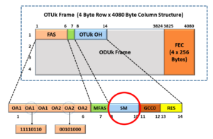
Figure 4a, The SM Field within the OTUk Overhead
Further, Figure 4b illustrates the SM byte’s location within the 3-byte SM Field (within the OTUk Overhead).

Figure 4b, The SM-Byte within the SM Field
Finally, Figure 4c shows the location of the BDI-field within the SM-byte (within the SM-field of the OTUk Overhead).
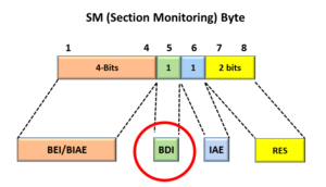
Figure 4c, The Location of the BDI bit-field within the SM Byte, within the SM Field, within the OTUk Overhead
Likewise, the Network Element will end its transmission of the OTUk-BDI indicator by setting the BDI bit-field back to “0” within each outbound OTUk frame.
How does the OTUk Network Element detect and declare the dBDI indicator?
In the scenario that we described above (via Figure 3), NETWORK ELEMENT EAST will continue to transmit the OTUk-BDI signal to NETWORK ELEMENT WEST as long as it (NETWORK ELEMENT EAST) declares the service-affecting defect within its Ingress (Receive) signal.
If NETWORK ELEMENT WEST receives the OTUk-BDI indicator within at least five (5) consecutive OTUk frames, it will declare the dBDI defect condition.
In other words, if NETWORK ELEMENT WEST (or any Network Element) were to receive at least five (5) consecutive OTUk frames, in which the BDI bit-field is set to “1”, then it will declare the dBDI defect.
Figure 5 illustrates NETWORK ELEMENT WEST declaring the dBDI defect after receiving five consecutive OTUk Frames with the SM-BDI field set to “1”.
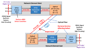
Figure 5, Illustration of NETWORK ELEMENT WEST declaring the dBDI defect condition
How does the OTUk Network Element clear the dBDI defect condition?
Whenever NETWORK ELEMENT EAST has determined that the service-affecting defect (which caused it to transmit the dBDI signal in the first place) is cleared, it will stop sending the dBDI signal back out to NETWORK ELEMENT WEST.
NETWORK ELEMENT EAST will stop sending the dBDI signal by setting the BDI bit-field (within the SM field) to “0” within each outbound OTUk frame.
If NETWORK ELEMENT WEST (which is currently declaring the dBDI defect condition) were to receive at least five (5) consecutive OTUk frames, in which the BDI bit-field is set to “0”, then it will clear the dBDI defect.
Figure 6 illustrates NETWORK ELEMENT WEST clearing the dBDI defect after receiving five consecutive OTUk Frames with the SM-BDI field set to “0”.

Figure 6, Illustration of NETWORK ELEMENT WEST clearing the dBDI defect condition
Monkey Pox and Covid? It’s Scary Out There. We Can Help You Become an Expert on OTN Before It’s Safe to Venture Out!! Click on the Banner Below to Learn More!!
Discounts Available for a Short Time!!
For More Information on OTN Posts in this Blog, click on the Image below.
