In this video, we presume that some ODUk- (or OTUk-) Layer circuitry is declaring a certain defect condition. We then determine how ODU-layer circuitry is expected to respond.
OTN – Lesson 10 – Handling Defects at the ODU-Layer – Defect Scenario for Multiplexed and Non-Multiplexed Applications
This video summarizes the various defects that OTN circuitry can declare/clear at the ODU-Layer.
This video also describes how ODU-Layer circuitry is expected to respond to each ODU-Layer (or upstream OTU-Layer) defect.
Should it transmit PM-BDI (Path Monitoring – Backward Defect Indicator) upstream?
Should it replace the under-lying 100oBASE-X or 100GBASE-R client signal with the Link or Local Fault Indicator?
This video answers these questions and more.
NOTE: This video covers both Non-Multiplexed and Multiplexed Applications.
This post presents the 6th of the 6 Videos that covers training on the Peformance Monitoring of the ODUk Layer (for Multiplexed Applications). This post focuses on the Sink Direction ODU-Layer Atomic Functions.
OTN – Lesson 10 – Video 6M – The ODU0_TT_Sk and ODUkP/CBR_ETC1000X_A_Sk Atomic Functions
This blog post contains a video that wraps up our discussion of the Sink (or Receive) Atomic Function circuitry for the ODU-Layer/Multiplexed Applications.
More specifically, this video includes a discussion of the following Atomic Functions.
This post presents the 4th of the 7 Videos that covers training on the Peformance Monitoring of the ODUk Layer (for Non-Multiplexed Applications). This post focuses on the Sink Direction ODU-Layer Atomic Functions. More specifically, this post includes a video that describes how the ODUk_TT_Sk Atomic Function declares and clears the dTIM, ODUk-AIS, dLCK and dOCI defect conditions.
OTN – Lesson 10 – Video 4N – More of the ODUk_TT_Sk Atomic Function
This blog post includes a video that continues to describe the role/functionality of the ODUk_TT_Sk atomic function.
In particular, this video explains how the ODUk_TT_Sk function declares and clears the following defect conditions.
In this video, we presume that some OTUk-Layer circuitry is declaring a certain defect condition. We then determine how OTU (and in some cases) ODU-layer circuitry is expected to respond.
OTN – Lesson 9 – Video 11 – OTU Layer Defect Scenarios
This blog post presents a video that discusses the various defects that OTN equipment can declare at the OTU Layer. Additionally, this video will describe how OTU Layer circuitry should respond to and handle these defect conditions.
This video will state whether OTU Layer circuitry should:
Transmit the SM-BDI Indicator upstream, or
Transmit the ODU-AIS Maintenance Signal downstream,
Increment Certain Performance Monitoring parameters, or
Halt Incrementing Certain Performance Monitoring parameters.
In response to each type of defect that OTU Layer circuitry can declare.
This video covers both Single-Lane (e.g., OTSi/OTUk_A_Sk) and Multi-Lane (e.g., OTSiG/OTUk_A_Sk) applications.
This post presents the 8th of the 11 Videos that covers training on Performance Monitoring at the OTUk Layer. This post focuses on the Sink Direction OTU-Layer Atomic Functions.
OTN – Lesson 9 – Video 8 – OTU Layer Sink Direction Circuitry/Functionality – Part 6
This blog post includes another video that continues our discussion of the OTUk_TT_Sk Atomic Function. In this video, we focus on the following aspects of this function.
How it declares and clears the dIAE (Input Alignment Error) Defect Condition
How it declares and clears the dBIAE (Backward Input Alignment Error) Defect Condition.
The dTIM (Trail Trace Identifier Mismatch) Defect Condition.
The dDEG (Section – Signal Degrade) Defect Condition
The type of signals that the OTUk_TT_Sk function outputs via the OTUk_AP Interface – particularly the AI_TSF and AI_TSD output signals.
This post briefly defines and describes Consequent Equations that ITU-T G.798 uses for OTN Applications.
What are Consequent Equations, and How Should You Interpret Them?
The purpose of this blog post is two-fold.
To describe the concept of Consequent Equations and
To discuss how we can use and interpret these Consequent Equations.
Introduction
Many ITU Standards (such as ITU-T G.798 for OTN Applications) will discuss many aspects of defects. These standards will define defects such as dAIS (Alarm Indication Signal) and dLOM (the Loss of Multi-frame).
These same standards will also define the criteria that an OTN Network Element (be it an STE or PTE) should use to declare or clear a given defect.
For example, ITU-T G.798 specifies all of the following defects that an OTN STE can declare and clear.
How should an STE/PTE Respond Whenever it Declares a Defect?
However, what else should an STE do whenever it declares (for example) the dLOF defect condition?
Does this STE have a responsibility to notify other STEs of this defect?
Similarly, what else should a PTE do whenever it declares (for example) the dTIM (ODUk-TIM) defect condition?
Again, does this PTE have a responsibility to notify other nearby PTEs of this defect?
The short answer to both of these questions is, “Yes, for those specific defects that I mentioned, they do have a responsibility to notify upstream and downstream equipment of the occurrence of those defect conditions.”
However, to confuse things, the PTE/STE must notify upstream and downstream PTE/STE whenever some defects occur, but not others.
How Do We Sort out This Confusion?
The Answer: Consequent Equations.
Let’s assume that a certain STE is declaring the dLOF Defect condition, as shown below in Figure 1.
Figure 1, Illustration of the STE (e.g., the OTSi/OTUk-a_A_Sk Atomic Function) declares the dLOF defect condition.
What happens next?
At this point, let’s write down the Consequent Equation that pertains to this STE (or the OTSi/OTUk-a_A_Sk function in this case):
AI_TSF-P is the current (logical) state of the AI_TSF-P input pin (to the OTSi/OTUk-a_A_Sk atomic function).
This consequent equation states that the STE (or OTSi/OTUk-a_A_Sk function) will assert its CI_SSF output pin anytime it declares any of the following defect conditions:
This consequent equation also states that the STE (the OTSi/OTUk-a_A_Sk function) will assert the CI_SSF output pin anytime the upstream atomic function asserts the AI_TSF input to this function.
NOTE: Please see the OTSi/OTUk_A_Sk Function Post for more information about this particular Atomic Function.
So What Does All of This Mean?
In Figure 2, I show the OTSi/OTUk_A_Sk function now asserting its CI_SSF output pin because it is currently declaring the dLOF defect condition.
Figure 2, Illustration of the OTSi/OTUk_A_Sk Atomic Function asserting its CI_SSF output because it is currently declaring the dLOF defect condition.
Please note that the CI_SSF output (from the OTSi/OTUk_A_Sk function) is connected to the CI_SSF input of the (downstream) OTUk_TT_Sk function.
OK, that’s great. The above Consequent Equation states that the STE (e.g., the OTSi/OTUk_A_Sk function will assert the CI_SSF output pin whenever it declares the dLOF defect.
How does that alert any other STE/PTE of the OTSi/OTUk_A_Sk function declaring the dLOF defect?
Answer: There is more to this, and it involves more Consequent Equations.
In Figure 3, I show the OTUk_TT_Sk and the OTUk/ODUk_A_Sk Atomic Functions.
I also show that the upstream (OTSi/OTUk_A_Sk function) circuitry is now asserting the CI_SSF input (to the OTUk_TT_Sk function) – as we described above.
Figure 3, Illustration of the OTUk_TT_Sk and OTUk/ODUk_A_Sk functions – with upstream circuitry asserting the CI_SSF input pin.
Now, the OTUk_TT_Sk Atomic Function happens to have two sets of Consequent Equations:
I will list each of these equations below.
aTSF <- CI_SSF or dAIS or (dTIM and (NOT TIMActDis))
aBDI <- CI_SSF or dAIS or dTIM
I will explain each of these equations below.
The First Consequent Equation – OTUk_TT_Sk Function
Let’s start with the first Consequent Equation for the OTUk_TT_Sk function.
aTSF <- CI_SSF or dAIS or (dTIM and (NOT TIMActDis))
Where:
aTSF is the current state of the AI_TSF output of the OTUk_TT_Sk Atomic Function.
CI_SSF is the current state of the CI_SSF input of the OTUk_TT_Sk Atomic Function.
dAIS is the current state of the dAIS defect condition, and
This Consequent Equation states that the OTUk_TT_Sk Atomic Function should assert the AI_TSF output signal anytime it declares any of the following defect conditions.
dTIM – Trail Trace Identifier Mismatch Defect
dAIS – AIS Defect
This Consequent Equation also states that the OTUk_TT_Sk function should assert the AI_TSF output whenever the upstream circuitry (e.g., the OTSi/OTUk_A_Sk function) asserts the CI_SSF input pin.
In Figure 4, I show the OTUk_TT_Sk function asserting its AI_TSF output pin because the upstream OTSi/OTUk_A_Sk function is asserting the CI_SSF input pin (to this function).
Figure 4, The OTUk_TT_Sk Atomic Function asserts the AI_TSF output pin because the upstream OTSi/OTUk_A_Sk function is asserting its CI_SSF input pin.
OK, now let’s look at the second Consequent Equation for the OTUk_TT_Sk Function.
The Second Consequent Equation – OTUk_TT_Sk Function
aBDI <- CI_SSF or dAIS or dTIM
Where:
aBDI is the state of the RI_BDI output (of the Remote Port Interface) of the OTUk_TT_Sk function.
Earlier in this post, we have defined CI_SSF, dAIS, and dTIM.
Therefore, this Consequent Equation states that the OTUk_TT_Sk function will assert the RI_BDI output pin anytime it declares the dAIS or dTIM defect conditions.
This equation also states that the OTUk_TT_Sk function will also assert the RI_BDI output pin anytime the upstream circuitry asserts the CI_SSF input (to the OTUk_TT_Sk function).
If you recall from the OTUk_TT_So and OTUk_TT_Sk posts, I state that anytime the OTUk_TT_Sk function asserts the RI_BDI output pin, it will command its collocated OTUk_TT_So function to transmit the OTUk-BDI indicator back out to the remote end.
I show this phenomenon below in Figure 5.
Figure 5, The OTUk_TT_Sk function asserts its RI_BDI output pin, commanding its Collocated OTUk_TT_So function to transmit the BDI (Backward Defect Indicator) back to the upstream STE because its CI_SSF is being driven HIGH.
Figure 5 shows that because the STE (OTSi/OTUk_A_Sk function) declared the dLOF defect, the downstream OTUk_TT_Sk function responded by commanding its collocated OTUk_TT_So function to transmit the OTUk-BDI indicator back to the upstream STE (the source of the defective OTUk signal).
However, we’re not done yet.
Since the OTUk_TT_Sk function is also asserting its AI_TSF output, it is also asserting the AI_TSF input to the (down-stream) OTUk/ODUk_A_Sk atomic function.
Has Inflation got You Down? Our Price Discounts Can Help You Fight Inflation and Help You to Become an Expert at OTN!!! Click Below to Learn More!!
Let’s move on to the OTUk/ODUk_A_Sk Atomic Function
As you can see in Figure 5, the OTUk_TT_Sk function, by asserting its AI_TSF output pin, is also asserting the AI_TSF input pin to the OTUk/ODUk_A_Sk function.
And the OTUk/ODUk_A_Sk function comes with several Consequent Equations of its own.
aSSF <- AI_TSF and (not MI_AdminState = LOCKED), and
aAIS <- AI_TSF and (not MI_AdminState = LOCKED)
Let’s take each of these equations, one at a time.
The First Consequent Equation – OTUk/ODUk_A_Sk Function
aSSF <- AI_TSF and (not MI_AdminState = LOCKED)
Where:
aSSF is the current state of the CI_SSF output pin (from the OTUk/ODUk_A_Sk function).
MI_AdminState reflects the current state of the MI_AdminState input signal (which the System Operator can set).
This Consequent Equation states that the OTUk/ODUk_A_Sk function will automatically assert its CI_SSF output signal whenever the upstream circuitry asserts its AI_TSF input, provided that the System Operator has not put the OTUk/ODUk_A_Sk function into the LOCKED state.
In Figure 6, I show the OTUk/ODUk_A_Sk function asserting its CI_SSF output pin because the upstream circuitry is asserting its AI_TSF input pin.
Figure 6, The OTUk/ODUk_A_Sk function asserts its CI_SSF output pin because the upstream circuitry (e.g., the OTUk_TT_Sk and OTSi/OTUk_A_Sk functions) is asserting its AI_TSF input pin.
I should also point out that APS (Automatic Protection Switching) systems often trigger (and start protection switching) whenever the OTUk/ODUk_A_Sk function asserts its CI_SSF output pin.
Now, let’s move on to the next Consequent Equation.
The Second Consequent Equation – OTUk/ODUk_A_Sk Function
If aAIS = TRUE, then the OTUk/ODUk_A_Sk function is overwriting its output signal with the ODUk-AIS Maintenance signal.
Conversely, if aAIS is FALSE, then the OTUk/ODUk_A_Sk function transmits an ODUk data stream, carrying regular client traffic.
Therefore, this Consequent Equation states that the OTUk/ODUk_A_Sk function will transmit the ODUk-AIS Maintenance Signal anytime the upstream circuitry pulls its AI_TSF input TRUE; provided that the System Operator has NOT put the OTUk/ODUk_A_Sk function into the LOCKED State.
In Figure 7, I illustrate the OTUk/ODUk_A_Sk function transmitting the ODUk-AIS Maintenance Signal because upstream circuitry (e.g., the OTUk_TT_Sk and OTSi/OTUk_A_Sk functions) is asserting its AI_TSF input.
Figure 7, The OTUk/ODUk_A_Sk function replaces the ODUk signal (carrying client data) with the ODUk-AIS Maintenance Signal whenever upstream circuitry asserts its AI_TSF input.
Then, we could state that if the OTN STE declares the dLOF defect (as we discussed earlier in this post), then that same OTN STE will do all of the following:
It will transmit the OTUk-BDI indicator back towards the upstream STE.
The OTN STE will also replace the missing (or defective) ODUk data stream (carrying client traffic) with the ODUk-AIS Maintenance Signal, and
It will also trigger APS (Automatic Protection Switching) activities by asserting the CI_SSF output (from the OTUk/ODUk_A_Sk function).
I show a drawing of these actions below in Figure 8.
Figure 8, Illustration of the OTN STE responding to the dLOF Defect Condition
Conclusion
Thanks to Consequent Equations, we can define and predict how an OTN STE or PTE will respond to certain defects.
I have presented Consequent Equations in each post pertaining to OTN Atomic Functions.
Clueless about OTN? We Can Help!! Click on the Banner Below to Learn More.
Discounts Available for a Short Time!!!
Click on the Image below to See More OTN- or Protection-Switching-Related Posts
This post briefly defines and explains what Defect Correlation means. In short, the Defect Correlation equations will specify how we expect a system to respond to a specific defect condition.
What is Defect Correlation, and How Should You Interpret It?
The purpose of this blog post is two-fold.
To describe the concept of Defect Correlation and
To discuss how to interpret the meaning of Defect Correlation and their Equations.
Introduction
Numerous ITU Standards (such as ITU-T G.798 for OTN applications) will define various aspects of defects. These standards will define a defect, such as dLOS (the Loss of Signal) and dLOF (the Loss of Frame).
These standards will (sometimes) describe the conditions that an OTN Network Element (be it an STE or PTE) should use to declare or clear a given defect.
For instance, ITU-T G.798 specifies all of the following defects that an OTN STE can declare and clear.
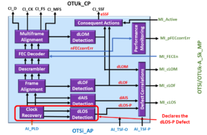
Figure 1, The OTSi/OTUk-a_A_Sk Atomic Function, declares the dLOS Defect Condition.
In either of these cases, it is clear that this OTN STE should declare the dLOS-P defect condition.
How about the dLOF Condition?
However, if that same OTN STE is not receiving any discernable signal from the remote STE, it is safe to say that it will not be receiving the FAS fields (within this now non-existent incoming data stream).
Should this OTN STE also declare the dLOF defect as well?
In Figure 2, I illustrate the OTSi/OTUk-a_A_Sk function, declaring the dLOF defect condition and the dLOS-P defect condition.
Figure 2, The OTSi/OTUk-a_A_Sk function declaring the dLOF and dLOS-P Defect Conditions
Clueless about OTN? We Can Help!! Click on the Banner Below to Learn More!!!
Corporate Discounts Available!!!
What about the dLOM Condition?
And since the OTN STE is not receiving any FAS field bytes, it cannot locate the MFAS bytes.
Should this OTN STE also declare the dLOM defect too?
In Figure 3, I illustrate the OTSi/OTUk-a_A_Sk function, declaring the dLOM, dLOF, and dLOS-P Defect conditions.
Figure 3, The OTSi/OTUk-a_A_Sk Atomic Function declaring the dLOM, dLOF, and dLOS-P Defect Conditions
How about the dTIM Condition?
Finally, since our OTN STE is not receiving any discernable signal (from the remote STE), and it cannot locate the boundaries of each incoming OTUk frame, it will certainly not obtain a Trail Trace Identification Message that matches that of the “Expected Trail Trace Identification” Message.
Should this OTN STE also declare the dTIM defect as well?
Figure 4, The OTUk_TT_Sk Atomic Function (downstream from the OTSi/OTUk-a_A_Sk Function) declares the dTIM defect.
Many Defects, all due to the dLOS-P Condition
In this scenario, a Loss of Signal event would cause the OTN STE to declare the dLOS, dLOF, dLOM, and dTIM defect conditions.
The OTN STE will accurately declare all four defect conditions because conditions warrant that the STE declare each of these defects.
However, allowing an STE to declare multiple defects (e.g., dLOS, dLOF, dLOM, and dTIM) can be confusing to both System-Management and the System Operator.
I could take this exercise even further and include some of the PTE/ODUk-related defects that an OTN PTE would declare (e.g., ODUk-AIS), all because of the dLOS-P condition. But I think that you get my point.
Whenever a service-affecting defect occurs, the OTN STE needs to alert System Management of a concise description of the problem (just dLOS-P in this case).
The intent should be to help the System Operator isolate the root cause of these problems.
We should not be bombarding the System Operator with a whole slew of defects, which are just artifacts of a single defect.
If the OTN STE declares the dTIM, dLOM, dLOF, and dLOS-P defects, the root cause of this problem has nothing to do with a mismatch in the Trail-Trace Identification Message.
Hence the Purpose of Defect Correlation
The purpose of Defect Correlation and Defect Correlation equations is to establish and report ONLY the root cause of problems to System Management.
The Defect Correlation Equations accomplishes this by creating a hierarchy of defects.
I’ll explain this.
Let’s list some Defect Correlation Equations for the OTSi/OTUk_A_Sk and OTUk_TT_Sk Atomic Functions.
cLOF ⇐ dLOF and (NOT dLOS-P) and (NOT dAIS) and (NOT AI_TSF-P)
cLOM ⇐ dLOM and (NOT dLOS-P) and (NOT dLOF) and (NOT dAIS) and (NOT AI_TSF-P)
Let’s also include the following Consequent Equation to bridge the OTUk_TT_Sk function to the OTSi/OTUk_A_Sk function.
aSSF ⇐ dLOS-P or dAIS or dLOF or dLOM or AI_TSF-P
For the OTUk_TT_Sk Function
In this case, we will focus on the Defect Correlation equation that pertains to the dTIM defect condition.
cTIM ⇐ dTIM and (NOT CI_SSF) and (NOT dAIS)
So Now Let’s Study some of these Defect Correlation Equations
Let’s start with the first equation for the OTSi/OTUk-a_A_Sk function.
cLOS-P ⇐ dLOS-P and (NOT AI_TSF-P)
Where:
cLOS-P is the correlated defect value of the dLOS-P defect state.
dLOS-P is the current state of the dLOS-P defect condition that the OTSi/OTUk_A_Sk function will declare or clear.
AI_TSF-P is the current state of the AI_TSF-P (Trail Signal Fail – Path Indicator) Input to the OTSi/OTUk-A_Sk function.
In this equation, the parameter that begins with the letter “c” is the correlated defect parameter (or defect) state that we ultimately report to System Management.
This equation states that we should only set the variable cLOS-P to TRUE if dLOS-P is TRUE.
In other words, we should only report the Loss of Signal condition (e.g., setting cLOS-P to TRUE) if the STE circuitry declares the dLOS-P defect (due to a lack of signal activity within the Clock Recovery Block, for example).
This equation also states that we should NOT set cLOS-P to TRUE because the upstream Optical Circuitry is declaring some other defect condition and is then asserting its AI_TSF-P output – towards the OTSi/OTUk_A_Sk function).
I show a TRUTH TABLE for this Defect Correlation Equation below in Table 1.
Table 1, TRUTH TABLE for the Defect Correlation Equation, cLOS-P ⇐ dLOS-P AND (NOT AI_TSF-P)
dLOS-P Defect
AI_TSF-P State
cLOS-P State
Comment
Cleared
FALSE
0
Declared
FALSE
1
Sets cLOS-P to TRUE, because dLOS-P is declared.
Don't Care
TRUE
0
We set cLOS-P to 0 when AI_TSF-P is TRUE.
Let’s look at another Defect Correlation Equation.
cLOF ⇐ dLOF and (NOT dLOS-P) and (NOT dAIS) and (NOT AI_TSF-P)
Where:
cLOF is the correlated value of the dLOF defect state.
dAIS is the current state of the dAIS defect condition within the OTSi/OTUk_A_Sk function.
In this equation, we are stating that we should only set cLOF = TRUE (and report the Loss of Frame condition to System Management) if the STE circuitry declares the dLOF condition.
This equation also states that we should NOT be setting cLOF = TRUE (and report the Loss of Frame Condition to System Management) if:
The STE is also declaring the dLOS-P defect, or
declaring the dAIS (OTUk-AIS) defect, or
If the upstream Optical Components assert the AI_TSF-P input to the OTSi/OTUk_A_Sk function.
If any of the three items (above) are TRUE, then we must set cLOF = FALSE.
I show the TRUTH TABLE for this Defect Correlation Equation below in Table 2.
Table 2, The TRUTH TABLE for the Defect Correlation Equation, cLOF ⇐ dLOF AND (NOT dLOS-P) AND (NOT dAIS) AND (NOT AI_TSF-P)
dLOF Defect Condition
dLOS-P Defect Condition
dAIS Defect Condition
AI_TSF-P State
cLOF State
Comments
Cleared
Cleared
Cleared
FALSE
Cleared
Declared
Cleared
Cleared
FALSE
Declared
We assert cLOF because we are declaring the dLOF Defect
Don't Care
Declared
Cleared
FALSE
Cleared
We set cLOF = 0 whenever dLOS-P is declared.
Don't Care
Cleared
Declared
FALSE
Cleared
We set cLOF = 0 whenever dAIS is declared.
Don't Care
Cleared
Cleared
TRUE
Cleared
We set cLOF = 0 whenever AI_TSF-P is driven TRUE.
At the risk of “whipping a dead horse,” I will show one more example.
cTIM ⇐ dTIM and (NOT CI_SSF) and (NOT dAIS)
Where:
cTIM is the correlated value of the dTIM defect state.
CI_SSF is the current state of the CI_SSF (Server Signal Fail Indicator) input pin to the OTUk_TT_Sk function.
If the STE circuitry declares this defect, this equation states that we must only report the Trail Trace Identifier Mismatch Defect (and set cTIM = TRUE).
This equation also states that we MUST NOT set cTIM = TRUE if any of the following is true.
If the upstream Optical Components assert the AI_TSF-P input to the OTSi/OTUk_A_Sk function.
If aSSF = TRUE, then the OTSi/OTUk_A_Sk function will assert the CI_SSF output signal (towards the OTUk_TT_Sk function).
Finally, we get to the bottom line.
These equations state that the STE MUST NOT set cTIM = TRUE (and MUST NOT report the Trail Trace Identifier Mismatch defect to System Management) if any of the following defect conditions are TRUE.
dLOS-P
dAIS
dLOF
dLOM
If the AI_TSF-P signal (from the upstream Optical Components) is HIGH.
Summary
I believe that you can see that using Defect Correlation Equations makes Defect Reporting and System-Management MUCH EASIER.
Has Inflation got You Down? Our Price Discounts Can Help You Fight Inflation and Help You Become an Expert on OTN!! Click on the Banner Below to Learn More!!!
Discounts Available for a Short Time!!
CLICK on the Image below for More OTN Related Blog Posts