This blog post defines and describes Unreliable Communication.
There are many ways to categorize the methods or manners of digital or electronic communication.
In other blog posts, we talked about Connection-Oriented and Connectionless Communication. Another way to categorize the various methods of communication is to divide these methods into the following groups.
Initially, if we were asked to choose between reliable or unreliable communication, most of us would choose reliable communication. On the surface, who in their right mind would choose unreliable communication over reliable communication?
However, if we truly understand the differences between these two forms of communication, then our choice may not be so obvious.
In this blog post, I will discuss unreliable communication. I will discuss reliable communication in another post.
About Unreliable Communication
In general, unreliable communication works as follows:
When the Sending Terminal sends a data frame and
The Receiving Terminal (that receives the frame) sends nothing back to the Sending Terminal.
In other words, the Receiving Terminal does not send an Acknowledgment back to the Sending Terminal.
Consequently, the Sending Terminal is NEVER HALTED.
The two Terminals send data to the other terminal whenever they have data to send.
That’s pretty much it!!
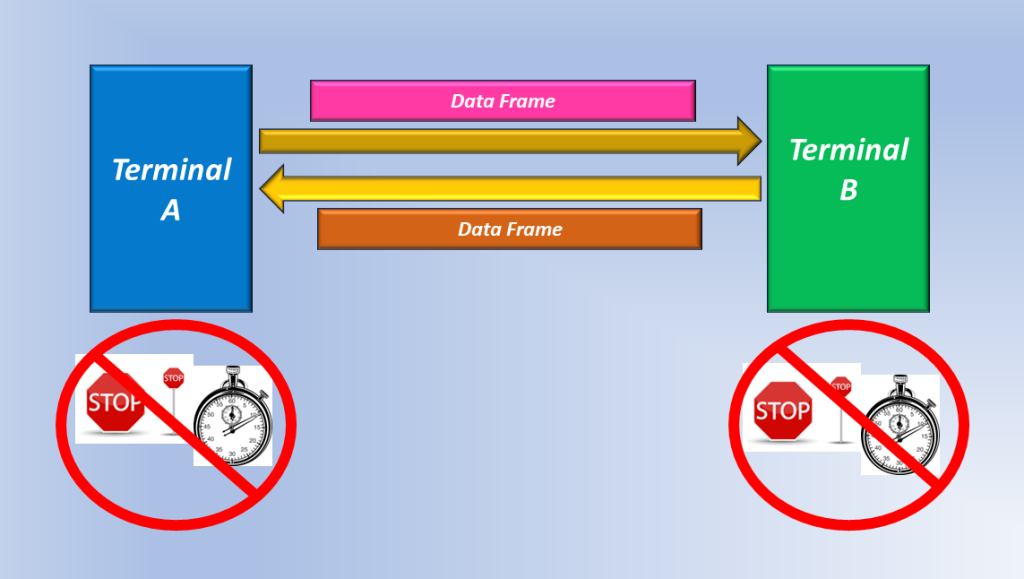
Figures 1 and 2 show the behaviors of two Terminals in an Unreliable Communication System.
Figure 1, Terminals A and B Sending Unrestrained Traffic (Data Frames) to each other. These terminals do not have Timers, nor are they ever halted.
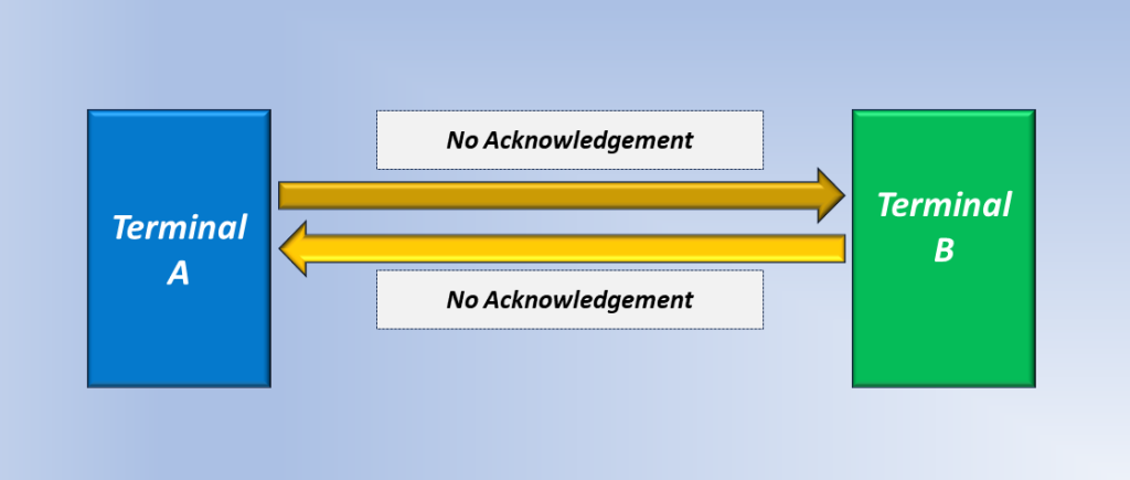
Figure 2, Terminals A and B DO NOT Send Any Acknowledgements to each other.
Why is Unreliable Communication sometimes preferred over Reliable Communication?
In real-time applications (such as real-time video applications, video streaming, or voice applications), the timely delivery of data is essential for the application to work and is also optimal for the customer experience.
In many of these applications, occasional bit errors within the data are not usually detrimental to the customer experience and enjoyment. Forcing the retransmission of frames (for example) due to bit-errors is far more disruptive for these services than the occasional bit-errors.
For An Unreliable Communication System to Work
The System Designer needs to make sure to either limit the data rate of the Sending Terminal or
Ensure that the Receiver always has sufficient bandwidth to handle the data rate/bandwidth from the Sending Terminal.
This way, the Sending Terminal will never swamp out or overrun the Receiving Terminal with excess data.
These constraints permit the Sending and Receiving Terminals to operate without any Flow-Control Mechanism (which requires Acknowledgements to function).
Applications that Require Unreliable Communication
Any real-time voice or video applications
Occasional bit errors are typically not a big problem for these applications, and
It is not worth interrupting real-time traffic flow to retransmit frames due to bit errors.
Once again, performing the retransmissions of erred frames is more disruptive (in these applications) than occasional data errors in traffic.
This blog post defines the term reliable communication. It also presents applications where we use reliable communication.
There are many ways to categorize the methods or manners of digital or electronic communication.
In other blog posts, we talked about Connection-Oriented and Connectionless Communication. Another way to categorize the various methods of communication is to divide these methods into the following groups.
Initially, if we were asked to choose between reliable or unreliable communication, most of us would select reliable communication. On the surface, who, in their right mind, would choose unreliable communication over reliable communication?
However, if we truly understand the differences between these two forms of communication, then our choice may not be so obvious.
In other words, there is a role for both reliable and unreliable communication. There are applications in which it is actually better to use unreliable communication.
In this blog post, I will discuss reliable communication. I will discuss unreliable communication in another post.
What is Reliable Communication?
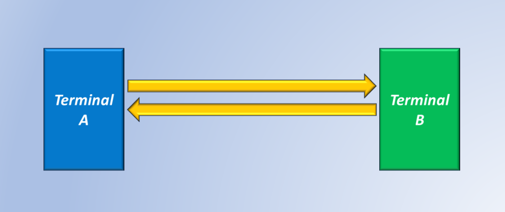
Let’s consider two Terminals (Terminal A and Terminal B) that are connected to each other.
Figure 1, Illustration of Terminal A and Terminal B Connected to Each Other.
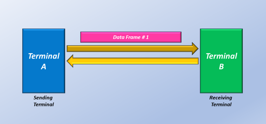
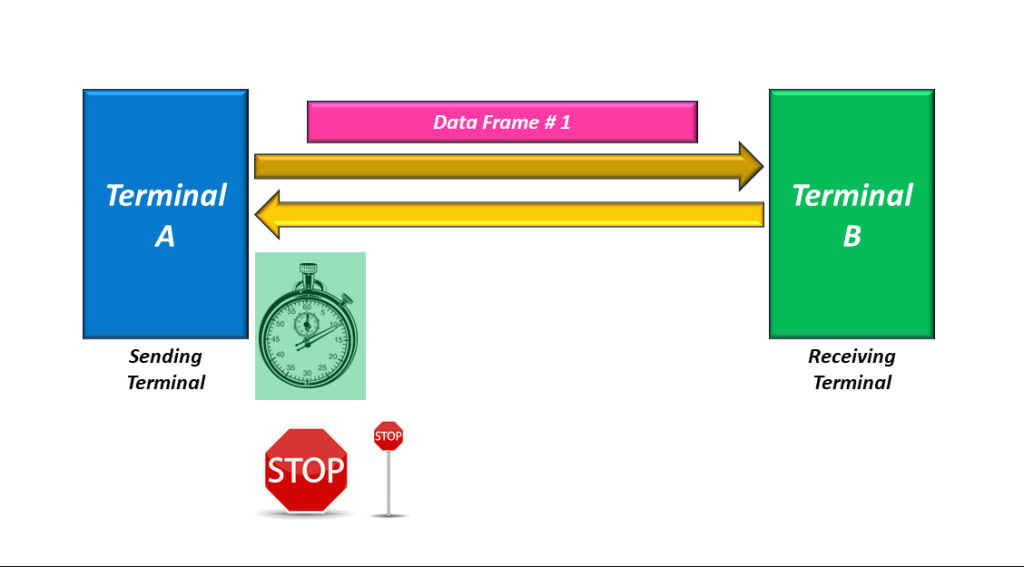
In a Reliable Communication system, a Terminal will transmit a block of data (say, a packet or a frame) to the other Terminal.
Figure 2, Illustration of Terminal A sending Data Frame # 1 to Terminal B.
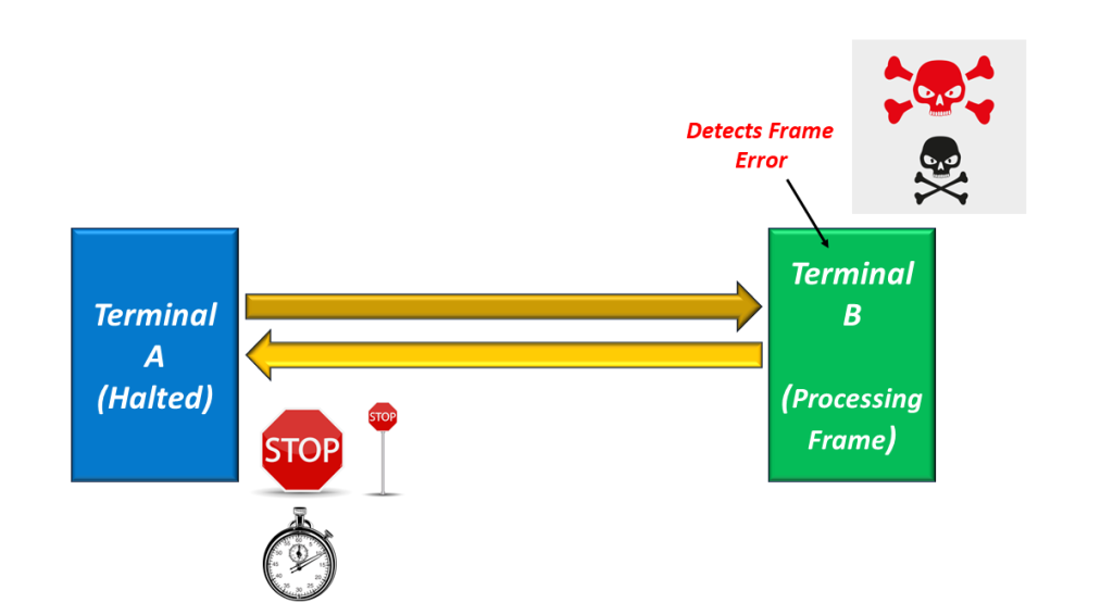
The Receiving Terminal (Terminal B in this case) will receive this frame and perform some error checking on this frame.
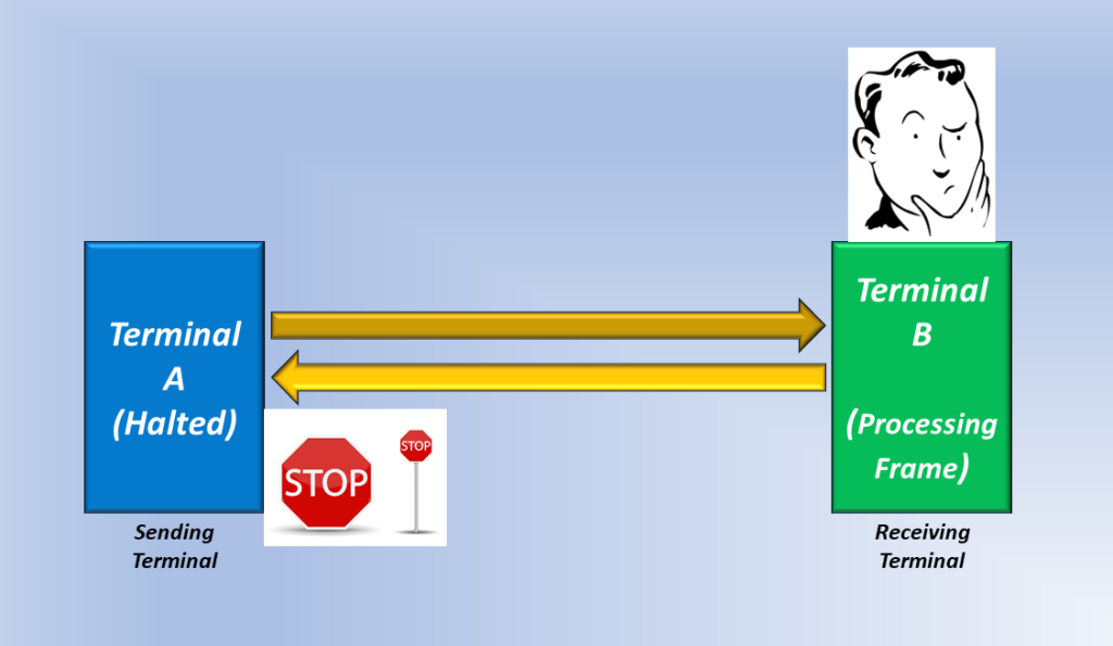
Figure 3, Illustration of the Receiving Terminal (Terminal B) processing and performing Error Checking on this frame that it has received from Terminal A.
Terminal A (the Sending Terminal) may also be halted for some time after sending this frame to Terminal B.
Figure 4, Illustration of Terminal A being “halted” after sending the Data Frame to Terminal B.
If the Receiving Terminal Detects No Errors within the Data Frame…
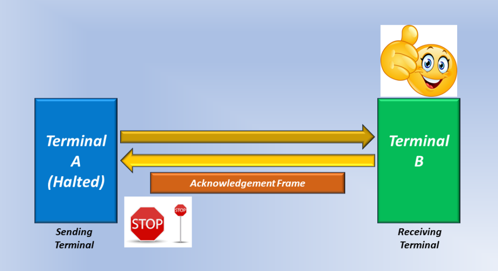
If Terminal B properly receives the Data Frame (with no errors or other problems), then it will send an Acknowledgment frame back out to Terminal A.
Figure 5, Illustration of Terminal B sending an Acknowledgment frame back out to Terminal A.
Once Terminal A (the Sending Terminal) receives this Acknowledgment Frame from Terminal B (the Receiving Terminal), it is no longer halted and can now send more frames.
Figure 6, Illustration of Terminal A being allowed to Send More Frames to Terminal B.
And this is the Essence of Reliable Communication.
The Essence of Reliable Communication
When everything works well, a Reliable Communication system will execute the following steps.
The Sending Terminal sends a Data Frame.
The Sending Terminal then HALTS and does not send any more frames (it is waiting for an Acknowledgment frame from the Receiving Terminal).
The Receiving Terminal processes this data frame (e.g., checks for Errors, Proper Sequence Numbers, etc.)
If the Receiving Terminal determines that this frame is GOOD, it returns an acknowledgment frame to the Sending Terminal.
The Sending Terminal is no longer HALTED and can now send more frames to the Receiving Terminal.
We just discussed Reliable Communication when everything is working fine. Let’s talk about Reliable Communication when things are not so good.
Reliable Communication in the Presence of Frame Errors
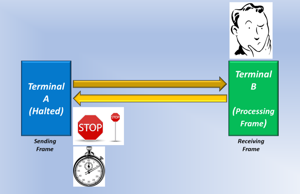
Once again, Terminal A sends a Data Frame to Terminal B. I should also mention that Terminal A will start a timer (within its circuitry). I will explain why we have this timer as we work through this scenario.
NOTE: These Terminals will always start a timer whenever they send a data frame to the remote Terminal.
This is true, even during the Good Conditions that I described above. I’m mentioning the timer now because it will be important in our discussion shortly.
Figure 6, Illustration of Terminal A sending a Data Frame to Terminal B.
As before, once Terminal A sends this frame to Terminal B, it will go into the HALT state until it gets an Acknowledgment frame from Terminal B.
However, in this case, Terminal B detects an error within the frame, as I show below in Figure 7.
Figure 7, Terminal B detects an error within the frame.
Now, there are a variety of protocols that the Receiving Terminal can use to respond to this error.
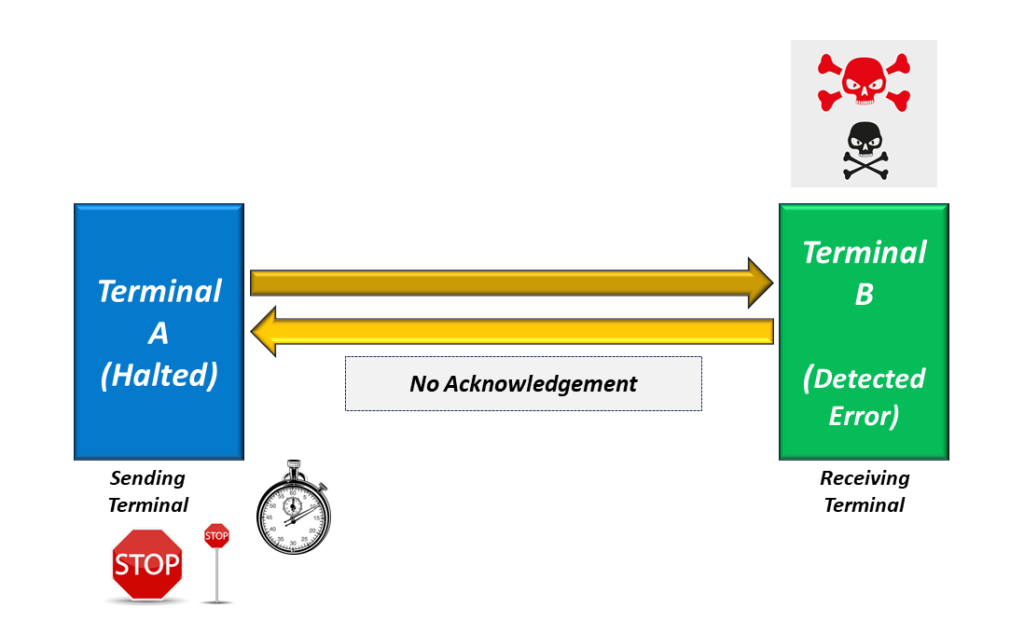
Receiving Terminal Does not Send an Acknowledgement Frame during Error Conditions.
However, we assume that Terminal B does nothing in this case. In other words, we will assume that Terminal B does not send an Acknowledgment frame back out to Terminal A when it detects an error.
In figure 8, Terminal B (after receiving an Errored Frame) does not return an Acknowledgment frame to Terminal A.
In this case, Terminal A is still in the HALT state, but only for a limited amount of time. The timer (that we just introduced) will eventually expire.
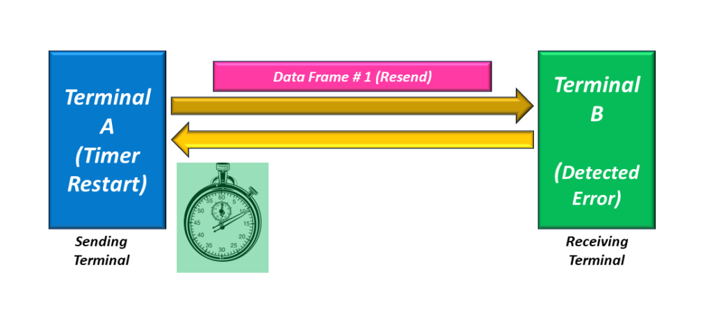
When this timer expires, Terminal A will resend the Data Frame (that it already sent). In this case, Terminal A correctly assumes that Terminal B did not properly receive the data frame (from Terminal A). So, Terminal A resends this frame to ensure that Terminal B ultimately receives this frame. Terminal A (once again) goes into the HALT state after re-sending this Data Frame (to Terminal B) again.
Figure 9, Illustration of Terminal A resending Data Frame # 1 to Terminal B.
Once Terminal B receives this retransmission of Data Frame # 1, it checks this frame again.
Figure 10, Illustration of Terminal B checking the Retransmission of Data Frame # 1.
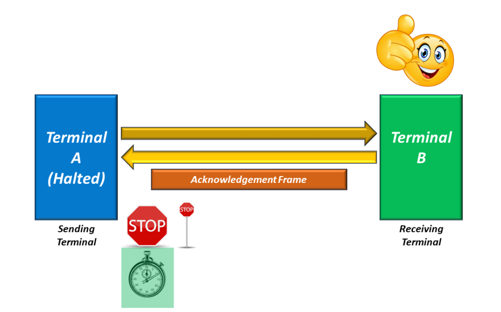
If Terminal B determines that the Retransmission of Data Frame # 1 contained no errors, then it will send an Acknowledgment back to Terminal A.
Figure 11, Illustration of Terminal B sending an Acknowledgement Frame back to Terminal A.
At this point, Terminal A exits the HALT state and can proceed to transmit data frames (to Terminal B) again.
More Information about the Timer
I mentioned earlier that each Terminal contains a timer. I want to spend some time talking about this timer.
When a Terminal sends a Data Frame to the remote terminal, in reliable communication, the Terminal also starts a timer and enters the HALT state.
The timer will run until the Sending Terminal receives an acknowledgment frame from the remote Terminal.
If the remote Terminal does not send the Acknowledgment frame, the timer will eventually expire and command the Sending Terminal to retransmit the same Data Frame.
On the other hand, if the Sending Terminal does receive an Acknowledgment frame (from the remote Terminal) before the timer expires, it will stop the timer and exit the HALT state.
The Sending Terminal will only restart the timer whenever it sends another data frame to the remote Terminal.
Let’s Once Again Review the Essence of Reliable Communication
The Sending Terminal sends a Frame to the remote Terminal, starts a timer, and goes into the HALT state.
The remote (or Receiving Terminal) receives and checks the Frame.
If the Receiving Terminal determines that the Data Frame is OK, it will send an Acknowledgment frame back out to the Sending Terminal.
If the Receiving Terminal determines that the Data Frame is NOT OK, it will NOT send an Acknowledgement frame back out to the Sending Terminal.
If the Sending Terminal receives an Acknowledgment frame from the Receiving Terminal, it it no longer halted and can send more frames to the Receiving Terminal.
On the other hand, if the Sending Terminal does not receive an Acknowledgment frame (from the Receiving Terminal) and the timer (within the Sending Terminal’s circuitry) expires, the Sending Terminal will retransmit the Data Frame that it was trying to send.
Applications Using Reliable Communication
File Transfer Protocol
Any service that transmits/receives a large amount of data (files)
Data Storage Applications and Servers
We will discuss unreliable communication in another post.
In this blog post, we will talk about Connectionless Communication and Connection-Oriented Communication in another blog post.
The Main Definition of Connectionless Communication
As I mentioned in another blog post, the main characteristic of “Connection-Oriented” Communication is that we must establish an end-to-end connection before communication begins.
This is not the case for Connectionless Communication.
The only thing that we require for Connectionless Communication is that at least one possible communication path must exist between Point A and Point B.
However, we do not need to go through a Connection Set-up Procedure before communicating.
Each block of data (or packets) is routed from the Source to the Destination terminals independently of that for the other packets.
Hence, not all packets necessarily flow along the same exact path.
This is in stark contrast to Connection-Oriented Communication.
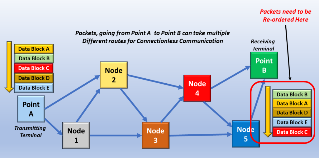
Since Packets Don’t All Follow the Same Path – For Connectionless Communication…
There might be a need for the Receiving Machine (at the Destination Terminal) to re-order the packets back into their correct sequence should they arrive at the Receiving Machine out of order.
In Figure 1, I show a group of packets arriving at the Receiving Terminal in a different order/sequence from that in which they were transmitted. This figure illustrates the case in which we would need to re-order the packet sequence at the Receiving Terminal.
Figure 1, Artifact of Connectionless Communication – Packets Do Not Necessarily Arrive (at the Receiving Terminal) in the Same Order as was Transmitted.
This was not the case for Connection-Oriented Communication.
In Figure 2, I show the sequence of packets (going through the Connection-Oriented Communication) in contrast to that for Connectionless Communication.
Figure 2, Artifact of Connection-Oriented Communications – Packets Do Necessarily Arrive (at the Receiving Terminal) in the Same Order as was Transmitted.
Network Transit Times for Packets will NOT be Constant.
Since each Packet will travel through a Connectionless Communication Network in a path independent of the other packets, the transit time for packets will not be constant (or nearly) the same for all packets.
Some packets experience more delay (or longer transit time – through the network) than others.
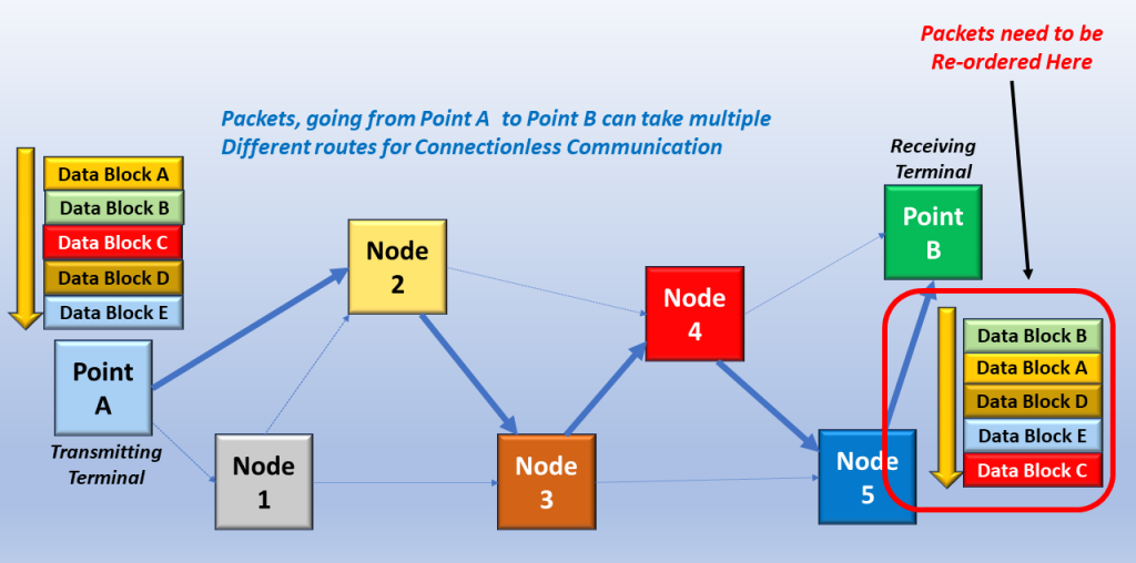
In Figure 3, I show a possible route for Packet # 1 through the network.
Figure 3, Possible Route for Packet # 1, through a Connectionless Network
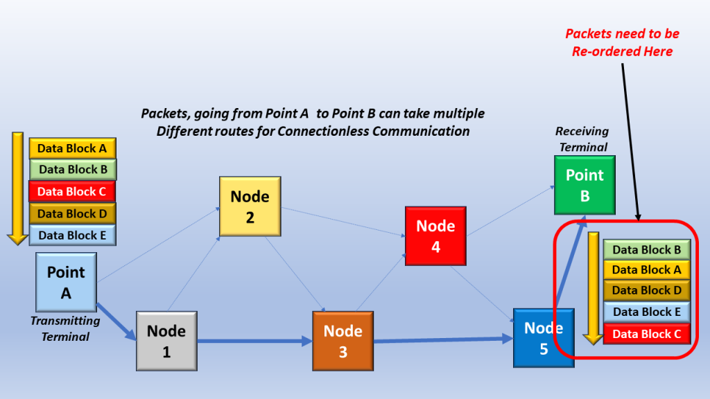
In Figure 4, I show the possible route for Packet # 2 through the Connectionless Network.
Figure 4, Possible Route for Packet # 2, through a Connectionless Network.
You can see that the possible routes for Packet # 1 and Packet # 2 can differ. This difference in path can result in different transit times between the two packets.
Why Would Packets be Routed Differently from Other Packets in a Connectionless Communication Network?
Some of the network circuitry may make different routing decisions based upon (for example) congestion levels or operational conditions within the paths between nodes.
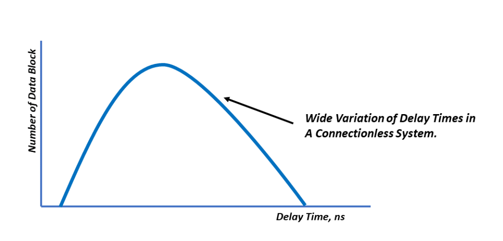
Consequently, Connectionless Communication will have a MUCH wider range of Propagation Delay times (to transit the network).
In Figure 5, I show a graph of the range of Delay (or Transit Times) through a Connectionless Network.
Figure 5, A Graph of the Possible Range of Delays (or Transit Times) through a Connectionless Network.
This feature (of Connectionless Communication) is often times not very good for real-time services, such as Voice or Video applications.
Advantages of Connectionless Communication
One up-side of Connectionless Communication is that it does NOT require dedicated bandwidth.
This means there is greater flexibility in using Connectionless Communication Media to support various services.
For example, if some services are idle (not using the Communication Media), this media is available to other services.
In other words, there is a dynamic allocation of bandwidth. Bandwidth can be allocated to various services on an as-needed basis.
Examples of Connectionless Communication
The Postal System (to Snail-Mail a letter).
You drop the letter in a mailbox
The letter gets “routed” to the Destination Address
But the exact path and time/date for arrival will vary.
Figure 6, Illustration of the Postal System – Connectionless Communication Network
Other Applications Using Connectionless Communication
In this blog post, we will talk about Connection-Oriented Communication; we will speak about Connectionless Communication in another blog post.
The Main Definition of Connection-Oriented Communication
The primary definition of Connection-Oriented Communication is that we must establish an end-to-end connection from Point A to Point B before communication can flow between Points A and B.
I show this requirement below in Figure 1.
Figure 1, An End-to-End Connection between Points A and B must be set up first.
Characteristics of Connection-Oriented Communication
Requires a Setup Phase or Procedure (before any communication can begin).
Data arrives (at the Destination) in the same order as it was sent (from the Source).
All data blocks (or packets) follow the same path from the Source to the Destination.
Once Communication has ended, the connection must be “torn down” to free up resources for other services.
Minimal variation in propagation delays (from the Source to the Destination).
This means the transit time through the connection is usually close to constant.
Typically involves the use of a dedicated link or communication media
Uses Static Bandwidth allocation as opposed to Dynamic Bandwidth allocation.
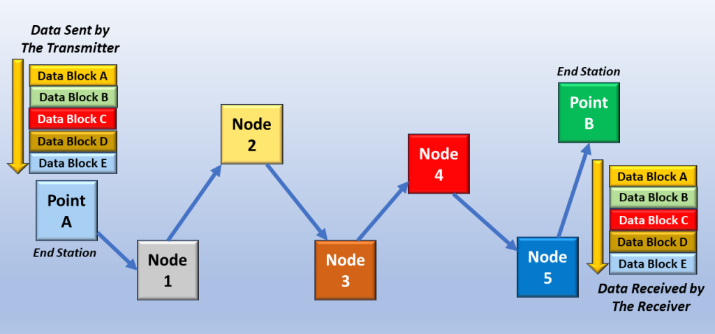
In Figure 2, I show one of the features of a Connection-Oriented Communication System. If we send Data Blocks A through E out (in that order), it will arrive at the other end in the same order (or sequence).
Figure 2, The Order/Sequence of Data, as it arrives at the Receiver, is the same as the order in which it was sent (at the Transmitter).
Hence, there is no need to re-order the sequence of data (to keep data in its proper order at the Destination).
Figure 3 shows another feature of a Connection-Oriented Communication System: the Nearly Constant Propagation Delay Times through the Network.
If it takes time, t, for a block of data to transit the network, it will typically take time, t, for all other blocks to traverse the network. There is minimal deviation in t for Connection-Oriented Networks.
Figure 3, All Data Blocks passing through a Connection-Oriented Communication System will have a Nearly Constant Propagation Delay time through the network.
This feature means that Connection-Oriented Communication is typically very good for real-time services (such as Voice or Video).
Some Disadvantages of Connection-Oriented Communication
One downside of Connection-Oriented Communication is that it does require dedicated bandwidth.
Other services are typically “locked out” and cannot use this bandwidth.
Examples of Connection-Oriented Communication
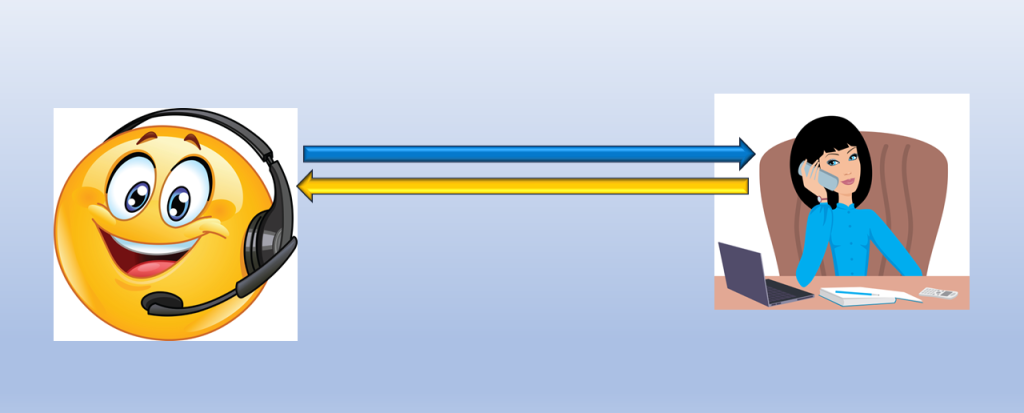
Voice Phone Call
You must dial your friend’s (or other party’s) number, and they MUST pick up their phone (completing the connection setup) before your conversation can begin.
Figure 4, Example of Connection-Oriented Communication – the Phone Call
Examples of Technologies/Protocols Using Connection-Oriented Communication
This blog post briefly defines the term Broadcast Communication. It also contrast Broadcast Communication with the terms Unicast and Multicast Communication.
In Computer Network Architecture, the three types of communication are:
These forms of communication can occur in Layer 2 (the Data Link Layer) and Layer 3 (the Network Layer).
NOTE: Layer 2 is the Data Link Layer. At this layer, the switch device works using MAC addresses for communication. Layer 3 is the Network Layer, where the router device uses the IP addresses for communication.
In this case, the word “cast” refers to how many people or devices we send data to. As I mentioned above, we can send data in a unicast, multicast, or broadcast manner.
I will briefly define these terms below.
Unicast Communication
Unicast: Means one-to-one communication. In this case, a single sender sends data to a single receiver or device.
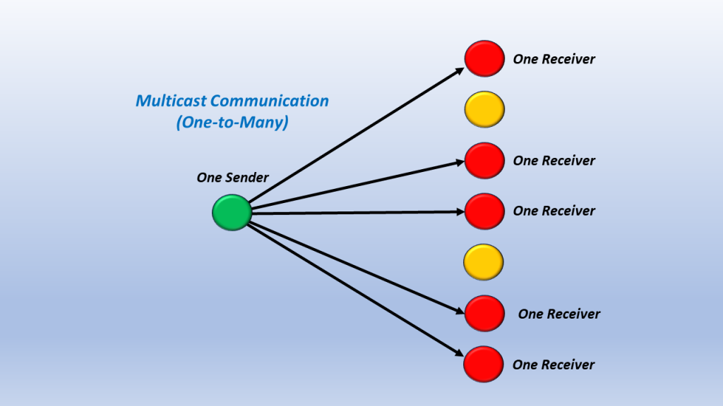
Multicast: This means one-to-many communication. In this case, a single sender sends data out to multiple devices in parallel. However, Multicast communication does not involve ALL DEVICES. Some devices on the network are excluded from this communication. This makes Multicast Communication different from Broadcast Communication.
Figure 2, Illustration of Multicast Communication.
Broadcast Communication
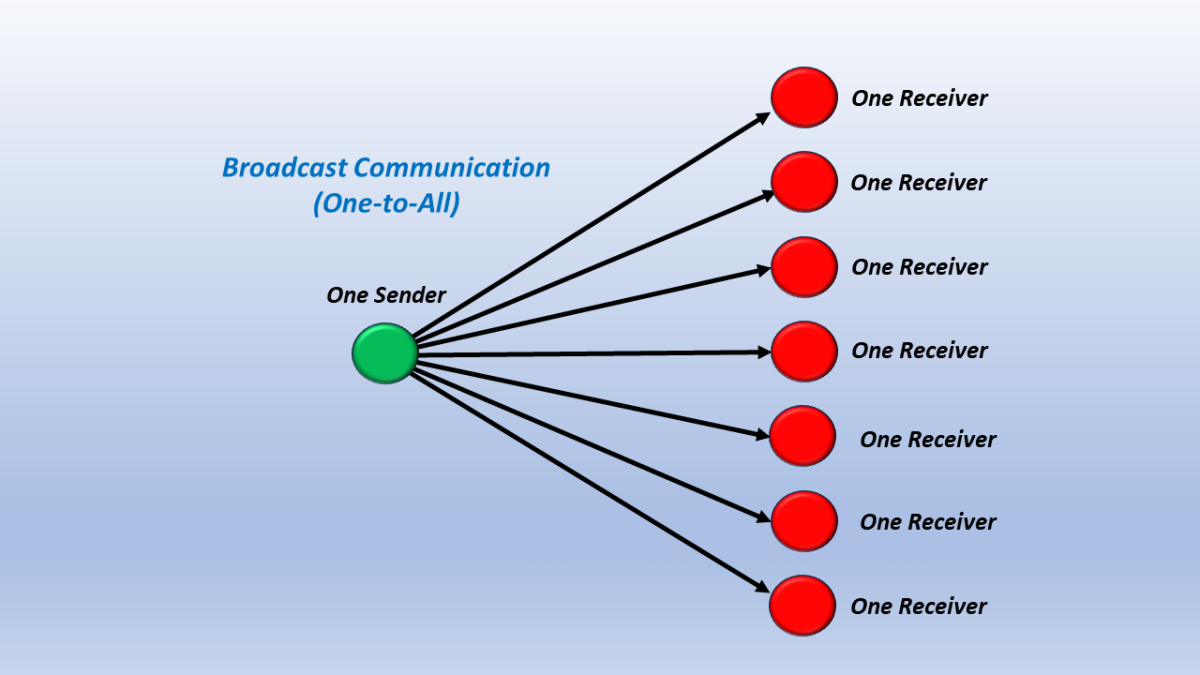
Broadcast: Means one-to-all communication. In this case, a single sender sends data to ALL network devices. Broadcast is different from Multicast Communication in that (for Broadcast) the sender sends information to ALL devices and excludes no one.
I show a simple illustration of Broadcast Communication below in Figure 3.
Figure 3, Illustration of Broadcast Communication.
What is Broadcast Communication?
Broadcast is a type of data transmission where data is sent from one device to all devices on a network.
In a Broadcast transmission, every packet is addressed to the network’s broadcast address. This means that every device on the network will receive the packet.
It is a one-to-all transmission which means there is one sender, but the information is delivered to all the connected receivers.
Broadcast is used for scenarios where a single device must communicate with all network devices.
We mainly use the term “broadcast” for cable TV transmission, where a broadcast sends TV signals from one source (one point) to all the possible destinations (all points).
Broadcast Communication is useful in network management packets such as ARP (Address Resolution Protocol) and RIP (Routing Information Protocol), where all the devices must see the data.
NOT All Network Technologies support Broadcast Communication.
Not all network technologies support Broadcast addressing. X.25 nor Frame Relay do not support broadcast communication.
IPv4 (Internet Protocol Version 4), which is and has been the primary networking protocol for Packet-Switching communication, supports Broadcast Communication. However, in this case, the broadcast domain is the broadcasting host subnet (which is typically small). There is no way to do an internet-wide broadcast. Broadcasting is mainly confined to the local area network (e.g., Ethernet).
IPv6, which is intended to be the successor to IPv4, does not support broadcast communication. IPv6 relies on multicast addressing/communication instead.
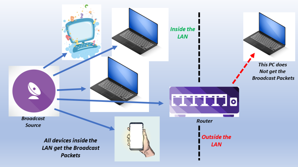
I show an illustration of Limited Broadcast Communication below in Figure 4.
Figure 4, Illustration of Limited Broadcast Communication.
Figure 4 shows that all packets will go to each receiver within the LAN for Broadcast Communication. However, this form of communication does not go past the router (which is outside of the LAN). Broadcast Communication is mostly for LAN-only communication.
Broadcast Communication is mainly for “within a LAN” communication. In other words, it only sends packets to devices within its Local Area Network.
When working with IPv4 packets, the Broadcast Address is 255.255.255.255. Whenever the Broadcast sends packets to this Broadcast Address, all devices (within the LAN) will receive these packets.
Unicast and Multicast do not have this restriction. These forms of communication can send packets outside of their LANs.
Broadcast Communication within an Ethernet Network
I present how we can support Broadcast Communication within the Destination Address field, in an Ethernet frame, in another post.
These forms of communication can occur in Layer 2 (the Data Link Layer) and Layer 3 (the Network Layer).
NOTE: Layer 2 is the Data Link Layer. At this layer, the switch device works using MAC addresses for communication. Layer 3 is the Network Layer, where the router device uses the IP addresses for communication.
In this case, “cast” refers to how many people or devices we send data to. As mentioned above, we can send data in a unicast, multicast, or broadcast manner.
I will briefly define these terms below.
Unicast Communication
Unicast: Means one-to-one communication. In this case, a single sender sends data to a single receiver or device.
Multicast: This means one-to-many communication. In this case, a single sender sends data to multiple devices in parallel.
However, Multicast communication does not involve ALL DEVICES. Some devices on the network are excluded from this communication. This makes Multicast Communication different from Broadcast Communication.
I show a simple illustration of Multicast Communication below in Figure 2.
Figure 2, Illustration of Multicast Communication.
Broadcast Communication
Broadcast: Means one-to-all communication. In this case, a single sender sends data to ALL network devices.
Broadcast is different from Multicast Communication in that (for Broadcast) the sender sends information to ALL devices and excludes no one.
Figure 3, Illustration of Broadcast Communication.
What is Multicast Communication?
Multicast is a type of data transmission where data is sent from one device to a group of devices on a network.
It is a type of one-to-many communication where a single packet of data is transmitted to multiple recipients simultaneously.
In a Multicast transmission, a single packet is addressed to a group of devices rather than to a single device like in Unicast. The packet is then replicated and sent to all devices in the group, allowing for more efficient network resource use.
Every packet is addressed to a multicast group address in a Multicast transmission. This means that only devices that have subscribed to the multicast group will receive the packet.
This characteristic (of communicating with many, but NOT ALL, receivers) makes multicast communication different from broadcast communication (in which a single device sends packets to ALL devices within the network).
Multicast transmission is widely used in applications such as video streaming, online gaming, and real-time communication, where the same data must be sent to multiple recipients simultaneously. For example, a video streaming application sends a video stream to a group of users watching the same video.
Examples of Applications using Multicast Communication
PPV Services for Events such as boxing matches or World Cup (Soccer Matches).
Streaming Services, such as Netflix, Sling, Hulu, Amazon Prime Video, and Disney+.
I show a simple illustration of Multicast Communication to realize a Live-Streaming Service below in Figure 4.
Figure 4, Illustration of Multicast Communication to realize a Live-Streaming Service.
Multicast Communication within Ethernet
I discuss how we support Multicast Communication within the Destination Address of an Ethernet frame, in another blog post.
This blog post briefly defines the term Unicast Communication. It also contrast this term with the definitions for Multicast and Broadcast Communication.
In Computer Network Architecture, the three types of communication are:
These forms of communication can occur in Layer 2 (the Data Link Layer) and Layer 3 (the Network Layer).
NOTE: Layer 2 is the Data Link Layer. At this layer, the switch device works using MAC addresses for communication. Layer 3 is the Network Layer, where the router device uses the IP addresses for communication.
In this case, the word “cast” refers to how many people or devices we send data to. As mentioned above, we can send data in a unicast, multicast, or broadcast manner.
I will briefly define these terms below.
Brief Definition of Unicast Communication
Means one-to-one communication. In this case, a single sender sends data to a single receiver or device.
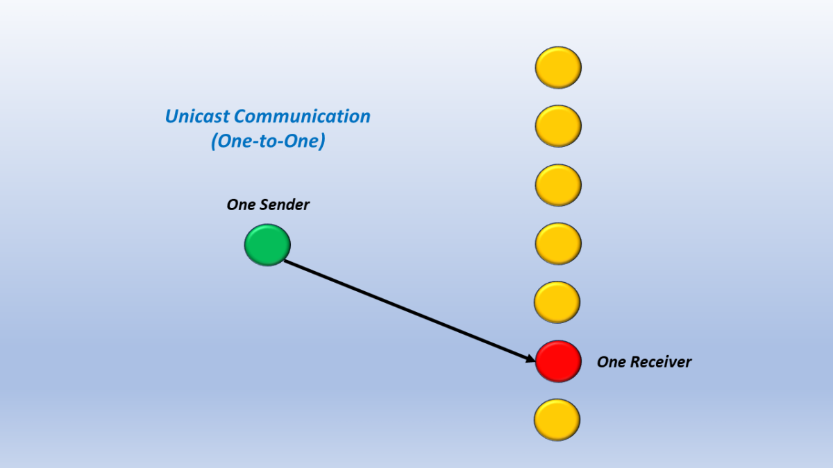
I show a simple illustration of Unicast Communication below in Figure 1.
Figure 1, Illustration of Unicast Communication.
Brief Definition of Multicast Communication
This means one-to-many communication. In this case, a single sender sends data out to multiple devices in parallel. However, Multicast communication does not involve ALL DEVICES. Some devices on the network are excluded from this communication. This makes Multicast Communication different from Broadcast Communication.
I show a simple illustration of Multicast Communication below in Figure 2.
Figure 2, Illustration of Multicast Communication.
Brief Definition of Broadcast Communication
Means one-to-all communication. In this case, a single sender sends data to ALL network devices. Broadcast is different from Multicast Communication in that (for Broadcast) the sender sends information to ALL devices and excludes no one.
Figure 3, Illustration of Broadcast Communication.
What is Unicast Communication?
In a Unicast transmission, a single sender sends data to a single receiver.
In this case, every packet (or frame) is addressed to a specific device on the network. We use unicast communication for point-to-point communication, where a single device (or station) communicates with another device or station.
Generally, we use unicast communication to send a message, browsing a website, downloading a file, etc.
Examples of Unicast Communication
If a device has an IP address of 21.2.4.0 in a network and wishes to transmit a packet to a device with an IP address 32.12.5.0 (in a different network).
I show an illustration of this below in Figure 4.
Figure 4, Illustration of a PC (with an IP address of 21.2.4.0) transmitting a packet to a device with an IP address of 32.12.5.0
4 computers are connected to a switch. If computer # 3 wants to directly communicate with computer # 2; this is unicast communication.
I show an illustration of this example below in Figure 5.
Figure 5, Illustration of 4 Computers connected together via a switch. Computer # 3 is now communicating with Computer # 2.
Whenever we use a computer to browse a website, the web server acts as a sender, and our computer acts as the receiver.
In Figure 6, I show an illustration of this particular example.
Figure 6, Computer (operating a web browser) while connected to a Web Server.
Downloading a file from an FTP server is an example of unicast transmission. In this case, the FTP server is the sender, and our computer is the receiver.
Unicast Communication within Ethernet
I provide a brief discussion on Unicast Communication and we use that within the Destination Address of an Ethernet frame, in another blog post.