

Introduction
The Destiination Address is a 6-byte (or 48-bit) field that follows the Preamble, within the Ethernet frame.
Whenever an Ethernet station transmits an Ethernet frame to one (or more other stations), the Destination Address identifies the intended recipient or recipients of this Ethernet frame. In other words, the Destination address identifies which station should receive this Ethernet frame.
Figure 1 shows an illustration of the IEEE 802.3 (Basic) Ethernet frame, with the Destination Address highlighted.

Figure 1, Illustration of the IEEE 802.3 (Basic) Ethernet frame, with the Destination Address highlighted.
Each Ethernet interface (or Station) is assigned a unique 48-bit address. We sometimes call this 48-bit Address the Physical, Hardware or MAC Address.
The Destination Address field (within the Ethernet frame) contains either:
- The 48-bit Ethernet address that corresponds to the address of the Ethernet interface in the station (which is the destination of the frame).
- A 48-bit multicast address, or
- The broadcast address.
As the Ethernet Receiver receives Ethernet frames, it reads the contents of every frame up to the Destination Address field. If the Destination Address value does not match the Interface’s own Ethernet address or one of the multicast or broadcast addresses that the interface is programmed to receive, then the Ethernet Receiver will ignore the rest of the Ethernet frame.
Conversely if the Destination Address value DOES match the interface’s own Ethernet address, or one of the multicast or broadcast addressse (that the interface is programmed to receive), then the Ethernet Receiver will accept and process the rest of the Ethernet frame.
The DIX Standard and the IEEE 802.3 Standards handle/interpret the Destination Address field slightly differently, as I describe below.
The DIX Standard for the Destination Address
We use the first bit of the Destination Address field (as transmitted onto the network medium) to distinguish physical addresses from multicast (or broadcast) addresses.
If this first bit (transmitted within the Destination Address) is zero (0), then the Destination Address field contains the physical address of an interface (or Station). We also refer to this address as the unicast address because we only send this Ethernet frame to this address only.
In Figure 2, I show an illustration of a simple “Unicast Address” within the Destination Address field.
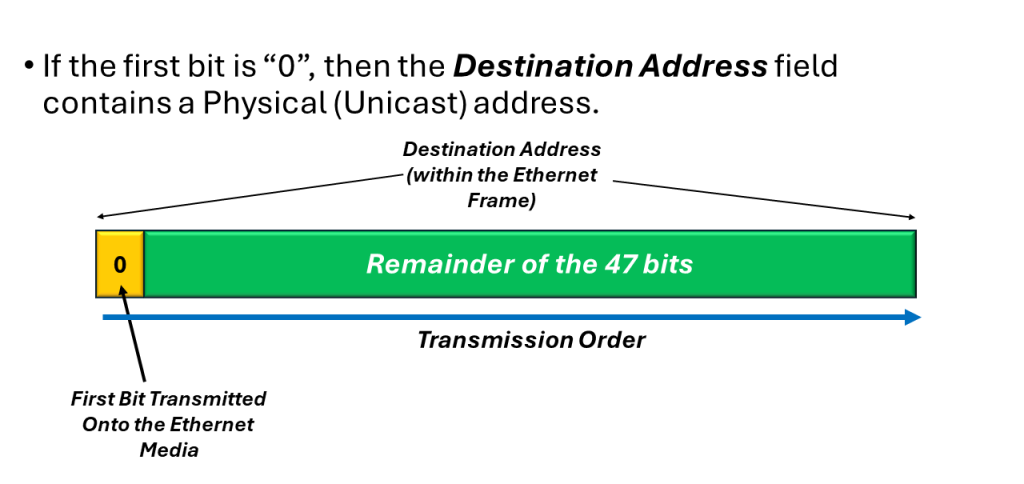
Figure 2, Illustration of a Simple “Unicast (or Physical) Address within the Destination Address field.
Please note that in Figures 2, 3 and 4, I am showing the Transmission Order of the bits, within the Destination Address (when one Ethernet station is transmitting an Ethernet frame to another station). I will discuss the bit-ordering (within an Ethernet frame) and how we transmit bits (within the Destination Address) from one Ethernet station to another station, below.
If the first bit (based on the transmission order onto the medium) is a one (1), then the Destination Address field contains a multicast address. If all 48-bits are set to “1” (e.g., an All Ones pattern), then the Destination Address field contains a broadcast (or all stations) address.
In Figure 3, I show a simple illustration of the Multicast Address, within the Destination Address field.

Figure 3, Illustration of the Multicast Address, within the Destination Address field.
In Figure 4, I show a simple illustration of the Broadcast Address, within the Destination Address field.
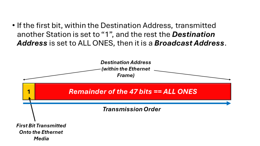
Figure 4, Illustration of the Broadcast Address, within the Destination Address field.
The IEEE 802.3 Standard for the Destination Address
The IEEE 802.3 standard (for the Destination Address field) interprets the first bit (transmitted within the Destination Address) the same way as for the DIX standard frames. However, IEEE 802.3 adds significance to the second bit within the Destination Address.
In this case, we use this second bit-field to distinguish between locally and globally administered addresses.
A globally administrated address is a physical address that an Ethernet Equipment Manufacturer assigned to the interface. If the network sets this 2nd bit-field is set to “0”, then this is a globally administered address.
NOTE: In the DIX Standard, we always globally administer Destination Addresses.
If the Ethernet Interface address is administered locally, then the second bit is typically set to “1”.
For example, in the case of the Broadcast Address, the 2nd bit, along with all other bits (within the Destination Address) are set to “1” in both the DIX and IEEE 802.3 standards.
NOTE: We rarely use Locally administered addresses in Ethernet networks. These days Ethernet Equipment Manufacturers assign each piece of Ethernet equipment its own unique 48 -bit Ethernet address during manufacturing. As I discuss in another blog post, these addresses are globally administered.
How We Transmit the Contents of the Destination Address
As I mentioned earlier, the Destination Address field consist of 6-bytes or 48-bits. To show the transmission order (along with the rest of the Ethernet frame), it is best to show an example.
Consider an Ethernet frame with the following Destination Address (below in the highlighted portion of Figure 5).
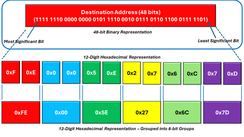
Figure 5, Illustration of the Breakdown of the Destination Address field
The length of the Destination Address is 48 bits (or 6 bytes). If we were to divide the bits (within this 48-bit field) into twelve (12) Nibbles, then you can express the contents within the Destination Address as 12 hexadecimal values – as I show below in the middle portion of Figure 6.

Figure 6, The Destination Address expressed as 12 (4-bit) Hexadecimal Values
We can then combine these 12 Hexadecimal bytes into 6 (two-digit) Hexadecimal Values. When we do that, then we can express the Destination Address as follows:
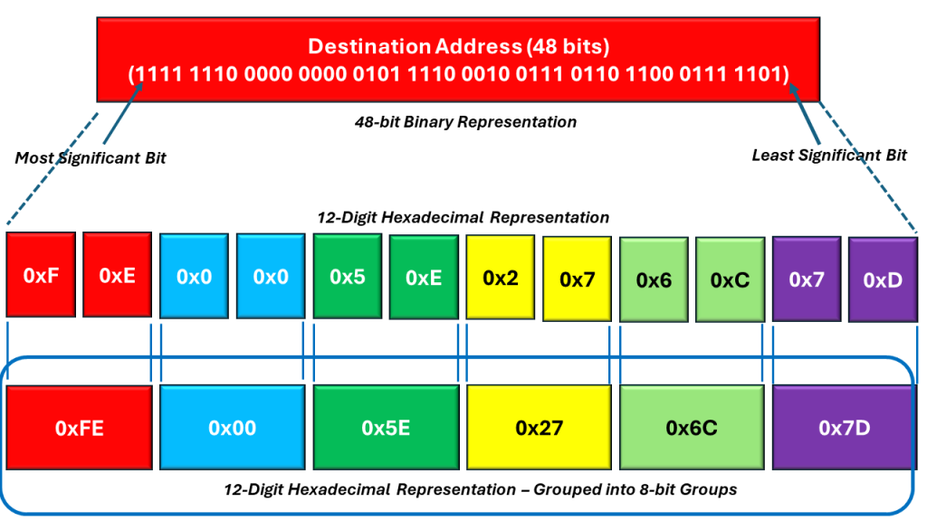
Figure 7, The Destination Address expressed as 6 (2 Digit) Hexadecimal Values
These 6 (2 Digit) Hexadecimal Values (of the Destination Address) are also the 6 bytes within the Desitination Address field.
The Transmission Order of the Destination Address
To transmit an Ethernet frame onto the media, we take the left-most byte (the byte in the red field) and then reverse the order of this byte (transmitting the right-most bit – within this particular byte first). We then proceed to transmit the remaining bits within this byte (all the way to the left-most bit). Next, we use the same procedure for the next byte (just to the right of this left-most byte, in the light blue field).
Figure 8 illustrates the resulting transmission order of the Destination Field, within the Ethernet frame.

Figure 8, The Transmission Order of the Destination Field, within the Ethernet field.
Determining Whether the Destination Address is a Unicast, Multicast or Broadcast Address
I mentioned that the network determines whether the Destination Address field is a Unicast, Multicast, or Broadcast address by the state of the very first bit (within the Destination Address field) that we place on the Ethernet media and transmit to the other station(s).
We stated that if the network sets this particular bit-field to “0”, then we are transmitting a Unicast Address. In Figure 9, I show that this particular Destination Address (that we are transmitting) is indeed a Unicast Address (because this first bit is set to “0”.

Figure 9, Illustration of the Destination Field, highlighting the Unicast/Multicast bit-field (Not in Transmission Order)
In Figure 9, we also show the location of this particular bit-field, within the Destination Field of the Ethernet frame. Once again, I show that we are transmitting a Unicast Address.
In Figure 10, I show an example of a Multicast Address (residing within the Destination Address field) of the Ethernet frame.
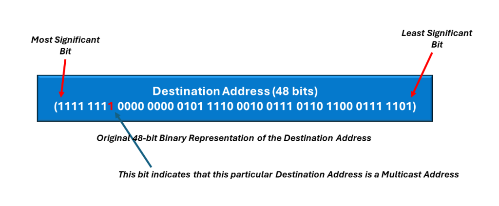
Figure 10, An Example of a Multicast Address within the Destination Address field of the Ethernet frame (Not in Transmission Order)
Finally, in Figure 11, I show an example of the Broadcast Address (residing within the Destination Address field) of the Ethernet frame.

Figure 11, Example of the Broadcast Address within the Destination Address field of the Ethernet frame. (Not in Transmission Order)