OTN – Lesson 12 – Continuation of Discussion of APS Commands for Protection Switching – Part III

This blog post contains a video that continues the discussion of the APS Commands. This video serves as Video 3 of this series of APS Command videos.

Lesson 12 – Video 10 – Detailed Discussion of APS Commands – Video 3

This blog post continues our discussion of APS Commands and the APS/PCC Communication Protocol. This video serves as Video 3 in this discussion. This blog post discusses completing the Force Switch Commands and the SF (Signal Fail) Commands using the APS/PCC Communication Protocol.

In particular, this video will discuss the following topics:

  • Executing the Force Switch – Normal Traffic Signal n to Protection (for the 1:N Protection Architecture) – Continued from Video 9
    • Implementing the Force Switch – NULL Test Signal to Protection Command – another way to resume Normal Operation.

Signal Fail APS Commands

  • Executing the Signal Fail – Working Transport Entity (SF_W) Command (for the 1+1 Protection Architecture)
    • How does a given Network Element invoke the SF_W Command?
    • The Protection Group’s operation during SF_W Command execution.
    • How do we recover from this Command (for a Reverting System)?
      • Use of the WTR (Wait-to-Restore) Command
  • Executing the Signal Fail – Protection Transport Entity (SF_P) Command (for the 1+1 Protection Architecture)
    • How does a given Network Element invoke the SF_P Command?
    • The Protection Group’s operation during SF_P Command execution.
    • How do we recover from this Command?
  • Executing the Signal Fail – Working Transport Entity (SF_W) Command (for the 1:N Protection Architecture)
    • How does a given Network Element invoke the SF_W Command?
    • The Protection Group’s operation during SF_W Command execution.
    • How do we recover from this Command (for a Reverting System)?
      • Use of the WTR (Wait-to-Restore) Command.
  • Executing the Signal Fail – Protection Transport Entity (SF_P) Command (for the 1:N Protection Architecture)
    • How does a given Network Element invoke the SF_P Command?
    • The Protection Group’s operation during the SF_P Command execution.
    • How do we recover from this Command?

Check Out the Video Below

Continue reading “OTN – Lesson 12 – Continuation of Discussion of APS Commands for Protection Switching – Part III”

OTN – Lesson 12 – Continuation of Discussion of APS Commands for Protection Switching – Part II

This blog post presents a video that continues our discussion of APS Commands via the APS/PCC Communication Protocol. This video serves as Part 2 of this discussion.

Lesson 12 – Video 9 – Detailed Discussion of APS Commands – Video 2

This blog post continues our discussion of APS Commands and the APS/PCC Communication Protocol. This video serves as Video 2 in this discussion. This blog discussed implementing the LoP (Lock Out of Protection) and Force Switch Commands using the APS/PCC Communication Protocol.

In particular, this video will discuss the following topics:

  • Executing the LoP (Lock Out of Protection Command) – for both the 1+1 and 1:N Protection Architectures
    • What does the LoP Command do to the Protection Group?
    • How do we Implement this Command?
    • How do we Terminate this Command (to resume Normal Operation)
  • Executing the Force Switch – Normal Traffic Signal to Protection (for the 1+1 Protection Architecture)
    • How does this command’s execution affect the Protection Group’s operation?
    • How do we Implement this Command?
    • Implementing the Force Switch – NULL Test Signal to Protection Command – to resume Normal Operation.
  • Executing the Force Switch – Normal Traffic Signal n to Protection (for the 1:N Protection Architecture)
    • How does this command’s execution affect the Protection Group’s operation?
    • How do we Implement this Command?
    • Implementing the Force Switch – Extra Traffic Signal to Protection Command – to resume Normal Operation.

To Learn More About the LoP (Lock Out of Protection) and Force Switch Commands, Check Out the Video Below.

Continue reading “OTN – Lesson 12 – Continuation of Discussion of APS Commands for Protection Switching – Part II”

OTN – Lesson 12 – Introduction to APS and the APS Communication Protocol for Protection Switching

This blog post presents a video that shows how to implement APS (Automati Protection Switching) both with and without using an APS Communication Protocol.

Lesson 12 – Video 8 – Detailed Discussion of APS without and with the APS Communication Protocol – Video 1

This blog post describes how we can implement APS (Automatic Protection Switching) without using an APS Communication Protocol. Afterward, this blog introduces how to implement APS using the APS Communication Protocol. This video serves as the first of several videos on this topic.

In particular, this video will discuss the following topics:

  • Executing APS without using the APS Communication Protocol
    • Under what conditions can we implement APS without using an APS Communication Protocol?
    • Why can we implement APS (without an APS protocol) in this case?
    • When not supporting an APS Communication Protocol, the Architecture/Design of the Protection-Switching Controllers.
    • How to implement Automatic Protection Switching – without implementing an APS Communication Protocol.
  • Executing APS with an APS Communication Protocol
    • Under what conditions must we implement APS with an APS Communication Protocol?
    • Why do we need to use an APS Communication Protocol for these cases?
    • How to implement Automatic Protection Switching – while using an APS Communication Protocol
      • Introduction to the APS/PCC Field for OTN/Linear Protection Switching Applications (per ITU-T G.873.1).
      • The Architecture/Design of the Protection-Switching Controllers – 1+1 Protection Architecture
      • The Architecture/Design of the Protection Switching Controllers – 1:N Protection Architecture
      • The NR (No Request) Command

To Learn How to Implement APS, with and without an APS Communication Protocol, Check Out the Video Below.

Continue reading “OTN – Lesson 12 – Introduction to APS and the APS Communication Protocol for Protection Switching”

Linear Protection Switching

This post briefly defines the term: Linear Protection Switching. It also briefly defines 1+1, 1:N Protection Architectures.


What is Linear Protection Switching?

A Linear Protection-Switching System is a Protection System (or Protection Group) that contains two nodes:

Each of these two nodes is exchanging normal traffic signals, with each other, over a protected network that consists of both the Working Transport entity and the Protect Transport entity.

I show some simple pictures of Linear Protection Switching Systems below in Figures 1, 2, and 3.

The 1+1 Protection-Switching Architecture

1+1 Linear Protection-Switching System

Figure 1, Illustration of a Linear Protection Switching System (A 1+1 Protection-Switching System)

In Figure 1, I show a simple illustration of a 1+1 Protection-Switching system, which also presents the bidirectional traffic flow between the Head-End and Tail-End Nodes.

If you want to learn more about the 1+1 Protection-Switching Architecture, check out the post on this topic.

The 1:N Protection-Switching Architecture

Linear Protection Switching - 1:2 Protection Switching Architecture

Figure 2, Illustration of a Linear Protection Switching System (A 1:2 Protection-Switching System) – for the East to West Direction

Linear Protection Switching - 1:2 Protection-Switching Architecture

Figure 3, Illustration of a Linear Protection Switching System (A 1:2 Protection-Switching System) – for the West to East Direction

Figures 2 and 3 each present an illustration of a 1:2 (or 1:N) Protection-Switching System.

Please note that the 1:N Protection-Switching Architecture figures are more complicated than that for the 1+1 Protection-Switching Architecture.

Therefore, I needed to show this architecture in the form of two figures. 

One figure shows the traffic flowing from West to East, and the other illustrates the traffic flowing from East to West.

If you want to learn more about the 1:2 (or 1:N) Protection-Switching architecture, check out the post on that topic.

In summary, the 1+1 and the 1:N Protection-Switching schemes are Linear-Protection Protection-Switching systems.

Design Variations for Linear Protection-Switching Systems

Linear  Protection-Switching systems are available in a wide variety of features.  I’ve listed some of these features and their variations below.

Architecture

Switching Type

Operation Type

APS Protocol – Using the APS/PCC Channel

Click on any of the links above to learn more about these design variations within a Linear Protection-Switching System.

What about Other Protection-Switching Architectures?

There are other types of Protection Switching systems, which are not Linear, such as Shared-Ring Protection-Switching or Shared-Mesh Protection-Switching.

Please see the relevant posts for more information about those types of Protection-Switching Systems.

Has Inflation got You Down? Our Price Discounts Can Help You Beat Inflation and Help You to Become An Expert on OTN!!! Click on the Banner Below to Learn More!!!

Discount Available for a Short Time!!

Click on the Image Below to see more Protection-Switching related content on this Blog:

Protection-Switching Related Blog

Protection-Switching Related Blog Posts

Protection-Switching Related Blog Posts Basic Protection-Switching Terms Head-End (Source Node) Hold-Off Timer Protection-Group Protection-Transport entity Selector Switch Tail-End (Sink Node) ...

What is the Head-End for Protection Switching?

This post defines and describes the term head-end for APS (Automatic Protection Switching) applications.


What is the Head-End, within an APS (Automatic Protection Switching) System?

ITU-T G.808 Defines the Head-end as:

The head-end of a protection group is the end where the bridge process is located.  If traffic is protected in both directions of transmission, the head-end process is present at every end of the protection group.  

NOTE:  Whenever people discuss the head-end of an APS system, they sometimes use the alternative term source-node.

ITU-T G.808 Defines the Source-Node as:

The node at the Ingress to a protected domain, where a normal traffic signal may be bridged to the protection transport entity.  

So What Does All This Mean?

In Figure 1, we show a drawing of a Protection Group.

If we were to look closely at the Normal Traffic Signal (within Figure 1), we would see that the Head-end is the first component that the Normal Traffic Signal passes through as it enters the Protection Group.

Protection Group - 1:N

Figure 1, Illustration of a Protection Group

The Head-end (or Source Node) is responsible for connecting the Normal and Extra Traffic Signals to the Working and Protect Transport entities, as appropriate for APS applications.

The Head-end will typically use a Bridge to connect the Normal Traffic signals and the Extra Traffic Signal (if available) to the Working and/or Protect Transport entities.

Automatic Protection Switching typically uses one of two types of Bridges.

  • The Permanent Bridge and
  • The Broadcast Bridge

We will discuss each of these bridges below.

The Permanent Bridge – (for the 1+1 Protection Switching Architecture)

If you use the 1+1 Protection Switching Architecture, you will typically use the Permanent Bridge.

The Permanent Bridge (as its name implies) permanently bridges (e.g., connects) the Normal Traffic Signal to both the Working and Protect Transport Entities.

Figure 2 presents an illustration of a Permanent Bridge.

Permanent Bridge

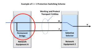
Figure 2, Illustration of a Permanent Bridge

This means that, for the 1+1 Protection Switching Architecture, the Working and Protect Transport entities always carry the Normal Traffic Signal.

In this case, the Bridge also acts as a “splitter” that transmits the Normal Traffic signal via the Working Transport entity and a replica of the Normal Traffic signal via the Protect Transport entity.

Figure 3 shows a drawing of a Protection Group that uses the 1+1 Protection Switching Architecture.

Protection Group - 1+1

Figure 3, Illustration of a Protection Group that uses the 1+1 Protection Switching Architecture

The Broadcast Bridge – (for the 1:1 and 1:n Protection Switching Architecture)

If you are using the 1:1 or 1:n Protection Switching Architecture, you will typically use the Broadcast Bridge.

For the one or n Working Transport entities (for the 1:1 or 1:n protection switching architectures, respectively), the Broadcast Bridge will permanently connect the Normal Traffic Signal to the Working Transport entity.

The Broadcast Bridge will (upon protection-switching controller command or configuration) also connect its corresponding Normal Traffic signal to the Protect Transport Entity.

We discuss the protection-switching controller in another blog post.

The 1:1 or 1:n Protection Switching Architecture may also include an Extra Traffic signal, which travels through the Protect Transport entity whenever none of the Working Transport entities declare service-affecting or signal degrade defect conditions.

Below, Figure 4 presents an illustration of the Broadcast Bridge.

Broadcast Bridge

Figure 4, Illustration of a Broadcast Bridge (for 1:1 and 1:n Protection Switching schemes)

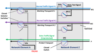
Additionally, Figure 5 presents an illustration of a Protection Group that uses the 1:2 Protection Switching Architecture and (thus) uses Broadcast Bridges within its Head-End circuitry.

1:2 Protection Switching System

Figure 5, Illustration of a Protection Group that uses the 1:2 Protection Switching Architecture

Summary

The Head-End (called the “Source Node”) is usually the first component that a Normal Traffic Signal will pass through as it enters a Protection Group.

The Head-End (or Source Node) performs a Bridging Function between the Normal Traffic Signal and the Working and Protect Transport Entities.

We use two basic types of bridging functions in Protection Switching applications.

The Permanent Bridge permanently connects the Normal Traffic signal to the Working and Protect Transport entities.

A Broadcast Bridge permanently connects the Normal Traffic signal to the Working Transport entities.

Finally, the Broadcast Bridge will (upon user command or configuration) also connect the corresponding Normal Traffic signal to the Protect Transport entity.

Has Inflation got You Down? Our Price Discounts Can Help You Beat Inflation and Become an Expert on OTN!! Click on the Banner Below to Learn More!!

Discounts Available for a Short Time!!!

Click on the Image Below to see more Protection-Switching related content on this Blog:

Protection-Switching Related Blog

Protection-Switching Related Blog Posts

Protection-Switching Related Blog Posts Basic Protection-Switching Terms Head-End (Source Node) Hold-Off Timer Protection-Group Protection-Transport entity Selector Switch Tail-End (Sink Node) ...

What is a Protection Group (APS)

This post defines the term Protection Group, for Automatic Protection Switching (APS) purposes.


What is a Protection Group for APS (Automatic Protection Switching) Purposes?

ITU-T G.808 Defines the Protection Group as:  

The collection of head-end and tail-end functions, 1 to n normal traffic signals, optionally an extra traffic signal, 1 to n working transport entities, and a single protection transport entity used to provide extra reliability for the transport of normal traffic signals.

What does all that mean?

The Protection Group comprises components and connections that work together to enhance the reliability of a transmission/network system for a Normal Traffic Signal by implementing Automatic Protection Switching.

Further, the Protection Group for a transmission/networking system consists of all the following items/entities.

The Protection Group enhances the reliability and protects 1 to N numbers of Normal Traffic Signals.

The Protection Group can either support Unidirectional or Bidirectional protection switching.

Figure 1 presents the Illustration of a 1+1 Protection scheme that I have modified to show the various elements within a Protection Group.

Protection Group - 1+1

Figure 1, Illustration of a 1+1 Protection Scheme that also identifies the Protection Group.

Likewise, Figure 2 illustrates a 1:2 Protection scheme that I have modified to show the various elements within the Protection Group.

Protection Group - 1:N

Figure 2, Illustration of a 1:2 Protection Scheme that also identifies the Protection Group.

In both cases, Figures 1 and 2 show numerous components within a shaded box.

All the items within the shaded box (in each figure) make up the Protection Group.

I discuss the individual components that make up the Protection Group in other posts within this post.

In Summary:

A Protection Group is a system that consists of the following items/entities:

Each of these components works together, using Automatic Protection Switching to enhance the transport path’s reliability for a given Normal Traffic Signal.

Has Inflation got You Down? Our Price Discounts Can Help You Beat Inflation and Help You Become an Expert on OTN!! Click on the Banner Below to Learn More!!

Discounts Available for a Short Time!!

Click on the Image Below to see more Protection-Switching related content on this Blog:

Protection-Switching Related Blog

Protection-Switching Related Blog Posts

Protection-Switching Related Blog Posts Basic Protection-Switching Terms Head-End (Source Node) Hold-Off Timer Protection-Group Protection-Transport entity Selector Switch Tail-End (Sink Node) ...