

What is a Revertive APS (Automatic Protection-Switching) System?
If an Automatic Protection System is Revertive, then that means that the system will always return to transmitting/accepting the Normal Traffic Signal through the Working Transport Entity anytime the system has recovered from a defect or an external request (for Protection Switching).
An Example of Revertive Switching
Let’s use an example to help define the term revertive.
The Normal/No Defect Case
Let’s consider a 1:2 Protection Switching System shown below in Figure 1.

Figure 1, Illustration of a 1:2 Protection Switching System – West to East Direction
NOTE: Because the 1:N Protection-Switching pictures are somewhat complicated, I only show the West-to-East Direction of this Protection-Switching system to keep these figures simple.
In Figure 1, all is well. Both of the Normal Traffic Signals within the figure (e.g., Normal Traffic Signal # 1 and Normal Traffic Signal # 2) flow from their Head-End Nodes to their Tail-End Nodes with no defects or impairments.
The Defect Case
Let’s assume that an impairment occurs within Working Transport Entity # 1 and that the Tail-End circuitry (associated with Working Transport Entity # 1) declares either a Service-Affecting or Signal Degrade Defect (e.g., declares the SF or SD condition).
We show this scenario below in Figure 2.
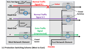
Figure 2, Illustration of our 1:2 Protection-Switching system (West to East Direction only) with a Service-Affecting Defect occurring in Working Transport Entity # 1
The Protection-Switch
Whenever the Tail-End circuitry (within Figure 2) declares the service-affecting defect condition, it will (after numerous steps) achieve the Protection-Switching configuration shown below in Figure 3.
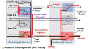
Figure 3, Illustration of our 1:2 Protection-Switching system (West to East Direction only) following Protection-Switching.
NOTE: Check out the post on the APS Protocol (within “THE BEST DARN OTN TRAINING PERIOD” training sessions) to understand the sequence of steps that the Tail-End and the Head-End Nodes had to execute to achieve the configuration we show in Figure 3.
Our 1:2 Protection-Switching system will remain in the condition shown in Figure 3 for the duration that the Tail-End Circuitry declares this defect within Working Transport Entity # 1.
The Defect Clears
Eventually, the Service-Provider will roll trucks (e.g., send repair personnel out to fix the fault condition, causing the service-affecting defect); and the defect will clear.
Once this service-affecting defect clears, the East Network Element will wait some WTR (or Wait-to-Restore) period before it proceeds with the Revertive switch.
Clueless about OTN? We Can Help!!! Click on the Banner Below to Learn More!!!
Corporate Discounts Available!!

The Revertive-Switch
Once the WTR period expires (with no further defects occurring within Working Transport Entity # 1), our Protection Group will switch and route Normal Traffic Signal # 1 back through Working Transport Entity # 1.
We show the resulting configuration below in Figure 4.
Figure 4, Illustration of our 1:2 Protection-Switching System (West to East Direction ONLY) following Revertive-Switch
The Overall Flow for Revertive Switching
Figure 5 presents a flow-chart diagram that summarizes the Revertive Protection-Switching Procedure.

Figure 5, Flow-Chart Diagram summarizing the Revertive Protection Switching Procedure
Check out the relevant post for more information about the Wait-to-Restore period and Timer.
In Summary
A Revertive Protection-Switching system will always perform a second switching procedure after the defect has cleared.
This second switching procedure will return the Protection Group to the state of having the Normal Traffic Signal flowing through the Working Transport Entity.
A Non-Revertive Protection-Switching system will NOT perform this second switching after the Tail-End Node has cleared the service-affecting defect.
Therefore, in a Non-Revertive Protection-Switching system, the Normal Traffic Signal will continue to flow through the Protection Transport entity indefinitely.
To use a Revertive Protection-Switching System or NOT.
There are advantages and disadvantages to using a Revertive system.
I list some of these advantages and disadvantages below.
Disadvantages of Using a Revertive System
- Each service-affecting or signal degrade defect (SD or SF) occurrence will result in two Switching Events. We will disrupt the Normal Traffic Signal twice for each defect condition.
- The first switching event is in response to the defect condition, and
- The follow-up Revert Switching event.
We strongly advise that you use Revertive Protection-Switching if:
- You are using a Shared-Ring Protection-Switching system.
- If the Bandwidth or Performance Capability of the Protection Transport entity is lower or worse than that for the Working Transport Entity (e.g., has more bit errors, inferior performance)
- Whenever there is a much more significant delay in the Protection Transport entity (than that for the Working Transport entity)
- If one needs to track which Protected ports are using the Working Transport entity and which are using the Protection Transport entities
- Protection Transport entity must be readily available for multiple other Working Transport entities (as in a 1:N Protection Architecture).
Has Inflation got You Down? Our Price Discounts Can Help You Beat Inflation and Help You to Become an Expert on OTN!! Click on the Banner Below to Learn More!!!
Discounts Available for a Short Time!!!

Click on the Image Below to see more Protection-Switching related content on this Blog:
