How an OTN STE should declare and clear the dLOM (Loss of Multi-Frame) Defect Condition.
The purpose of this post is to describe how an OTN STE (Section Terminating Equipment) will declare and clear the dLOM (Loss of Multi-Frame) Defect Condition.
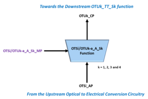
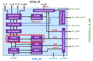
Suppose you’re analyzing this topic from an ITU-T G.798 Atomic Function standpoint. In that case, I will tell you that the two atomic functions that are responsible for declaring and clearing the dLOM defect condition are:
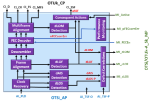
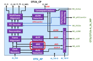
Each of these atomic functions includes the dLOM Detection circuit.
A Note about Terminology:
Throughout this blog post, I will refer to the entity containing the dLOM Detection circuit (and declares/clears the dLOM defect condition ) as the Sink STE.
I’m using this terminology because it is technically correct, and it is much simpler to use that word than to use: OTSi/OTUk_A_Sk or OTSiG/OTUk_A_Sk functions. However, I will use atomic function-related terms below in Table 1 (at the end of this post).
A Brief Review of the OTUk Frame Structure
In the OTUk Post, I stated that the OTUk frame consists of a single multi-frame alignment signal (MFAS) byte.
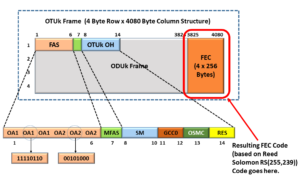
I show a drawing of the OTUk Frame Structure, with the MFAS-field highlighted below in Figure 1.

Figure 1, Drawing of the OTUk Frame Structure, with the MFAS-Field Highlighted
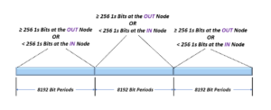
In the OTUk blog post, we mentioned that the Source STE Terminal would generate and transmit OTUk traffic in the form of back-to-back multi-frames. Each of these multi-frames consists of 256 consecutive OTUk frames.
The MFAS Byte Increments with each Frame
The S0urce STE Terminal will designate one of these OTUk frames as the first frame within a multi-frame by setting the MFAS byte (within that particular frame) to 0x00. When the Source STE generates and transmits the next OTUk frame, it will set the MFAS byte (within that OTUk frame) to 0x01.
The Source STE will continue incrementing the MFAS byte within each outbound OTUk frame until it has transmitted the 256th frame within this multi-frame. And it has set the MFAS byte to 0xFF (or 255 in decimal format).
At this point, the Source STE has completed its transmission of a given 256-frame OTUk multi-frame, and it will start to transmit the very next multi-frame.
The Source STE will show that it is transmitting the next 256-frame multi-frame by setting the MFAS byte to 0x00 (once again) and then incrementing the value that it writes into each MFAS byte (within each outbound OTUk frame) until it reaches 0xFF (255).
This process repeats indefinitely.
Now that we have re-acquainted ourselves with the MFAS byte, we can discuss how a Sink STE will declare and clear the dLOM (Loss of Multi-frame) defect condition.
Has Inflation got You Down? Our Price Discounts Can Help You Fight Inflation and Help You Become an Expert on OTN Before!!! Please Click on the Banner Below to Learn More!!
Corporate Discounts Available!!

A Basic Requirement before We can Clear the dLOM Defect Condition
Before I can begin to discuss the dLOM-Related State Machines (and the actual mechanics of declaring and clearing the dLOM defect). I need to be very clear about one thing.
The Sink STE can’t clear the dLOM defect condition unless it has first cleared the dLOF defect condition.
Additionally, anytime the Sink STE declares the dLOF defect condition, it loses MFAS synchronization.
There are several reasons for this:
The Sink STE needs to find the FAS-field first
The MFAS byte-field resides in Row 1, Byte 7 (within the OTUk frame). It is adjacent to the FAS field. Therefore, once the Sink STE finds the FAS field, it can quickly locate the MFAS byte.
The FAS field is FAR more accessible for the Sink STE to find than the MFAS byte.
There are two reasons for this.
The FAS field consists of a defined/fixed pattern. In other words, the FAS fields never change in value (except for the 3rd OA2 byte – for OTL4.4 and OTL4.10 applications ONLY).
The Sink STE can locate the FAS field by only looking for these fixed patterns. On the other hand, the MFAS byte value changes with every OTUk frame.
Additionally, we NEVER scramble the FAS field. However, we do scramble the MFAS byte.
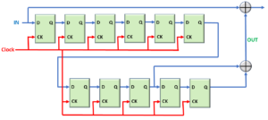
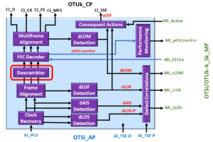
I show a drawing of an OTUk frame below that identifies the portions of the OTUk frame that the Remote Source STE has scrambled before transmitting this OTUk frame to the Near-end Sink STE.

Figure 2, Drawing of an OTUk Frame – Showing the portions of the OTUk Frame that we scrambled.
Finally, the MFAS byte-field was scrambled by a Frame-Synchronous Scrambler (at the remote Source STE)
Therefore, you will need to descramble the MFAS byte (along with the rest of the OTUk frame) with a Frame-Synchronous Descrambler.
This means that the Sink STE needs proper synchronization with the incoming OTUk frames (e.g., clearing the dLOF defect) before we can even use this Frame-Synchronous Descrambler.
Now that I’ve made that point, I will discuss how the Sink STE declares and clears the dLOM defect.
We will first discuss dLOM-Related State Machines.
The dLOM-Related State Machines
Once again, whenever the Sink STE first powers up and receives a stream of OTUk data, it will first need to acquire FAS-frame synchronization with this incoming data stream, as described in the dLOF – Loss of Frame Defect blog post.
After the Sink STE has cleared the dLOF defect condition (and can now reliably locate the FAS field within each incoming OTUk frame), it can proceed to find the MFAS byte.
Figure 1 (above) shows that the MFAS byte resides in row 1, byte-column 7 (immediately following the FAS field) within the OTUk frame.
Whenever the Sink STE has acquired FAS-frame synchronization with the incoming OTUk frame (and cleared the dLOF defect condition), it will continuously operate simultaneously per two sets of state machines.
- The OTUk-MFAS OOM/IM Low-Level State Machine and
- The OTUk-dLOM Framing Alignment/Maintenance State Machine
These two state machines are hierarchical. In other words, one of these state machines operates at the low level (e.g., the OTUk-MFAS OOM/IM Low-Level State Machine), and the other state machine operates at a higher layer (on top of the low-level state machine).
I show the relationship between these two-state machines below in Figure 3.
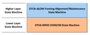
Figure 3, Illustration of the relationship between the two dLOM-related State Machines
We will discuss these two state machines below.
The OTUk-MFAS OOM/IM Low-Level State Machine
We will discuss the OTUk-MFAS OOM/IM Low-Level State Machine first, and then we will discuss the OTUk-dLOM Framing Alignment/Maintenance State Machine later.
I show a drawing of the OTUk-MFAS OOM/IM Low-Level State Machine Diagram below in Figure 4.

Figure 4, Drawing of the OTUk-MFAS OOM/IM Low-Level State Machine Diagram
Figure 4 shows that the OTUk-MFAS OOM/IM Low-Level State Machine contains the following two states.
- The LL-OOM (Low-Level – Out of Multi-frame) state and
- The LL-IM (Low-Level – In Multi-frame) state
When the System Operator powers up the Sink STE circuitry, feeds an OTUk data stream and clears the dLOF defect, it will continually operate in one of these states.
The Sink STE will (on occasion) need to transition from one state to another.
We will discuss these two states below.
The LL-OOM State
Whenever the Sink STE first clears the dLOF defect condition, it will (initially) be operating in the LL-OOM (Low Level – Out of Multi-Frame) state.
At this point, the Sink STE either has not located the MFAS byte or is not yet in sync with the incrementing MFAS byte value within the incoming OTUk data stream.
While the Sink STE is operating in this state, it will begin to evaluate bytes (that it “believes” to be the MFAS byte-field) within each incoming OTUk frame. More specifically, the Sink STE will locate a given Candidate MFAS byte and read in its value.
The value of this MFAS byte will be between 0x00 and 0xFF (255) inclusively. The Sink STE will note this value, and it will then perform the following computation.
Next_Expected_MFAS_Value = MOD(Candidate_MFAS_Value + 1, 256);
In other words, the Sink STE will take the byte value (of the Candidate MFAS byte that it has read in) and (internally) increment this value by 1.
I hope you understand why we run this incremented Candidate_MFAS_Value through a Modulus Equation with a divisor of 256.
The Sink STE will assign this newly incremented value to the variable Next_Expected_MFAS_Value. We will use this “Next _Expected_MFAS_Value” to evaluate the next incoming OTUk frame.
The Sink STE will then wait through 16,320-byte periods (or one OTUk frame period) and then read in another Candidate MFAS value (from this next OTUk frame), and it will compare that byte value with the “Next_Expected_MFAS_Value” that it has computed.
If the Sink STE determines that this new “Candidate MFAS Value” does not match the “Next_Expected_MFAS_Value,” then it will go back and parse through the incoming OTUk data-stream and look for another byte-field (within row 1, column 7 of the incoming OTUk frame).
The Sink STE will continue to operate in the LL-OOM state.
On the other hand, if the Sink STE does (indeed) determine that the expression “Candidate MFAS value ” matches that of the “Next_Expected_MFAS_Value,” then it will transition into the LL-IM (Low-Level – In-Multi-Frame) state.
The LL-IM State
Once the Sink STE enters the LL-IM state, then it will continue to check for the presence of the correct (properly incrementing byte values within the MFAS byte) at OTUk frame intervals.
If the Sink STE can consistently locate these MFAS bytes at each OTUk frame interval (with the correct and properly incrementing values), it will remain in the LL-IM state.
However, if the Sink STE lost synchronization with the MFAS field (of each incoming OTUk frame), it could not locate the MFAS field for five (5) consecutive OTUk frame periods, then the Sink STE will transition back into the LL-OOM state.
NOTE: The OTUk-MFAS OOM/IM Low-Level State Machine algorithm is tolerant of bit errors. In other words, the presence of occasional bit-errors or a burst of bit-errors is not enough to cause the Sink STE to transition from the LL-IM back to the LL-OOM state.
Now that we have discussed the OTUk-MFAS OOM/IM Low-Level State Machine, let’s move on and describe the OTUk-dLOM Framing Alignment/Maintenance State Machine.
Clueless about OTN? We Can Help!! Click on the Banner Below to Learn More!!!
Discounts Available for a Short Time!!!
The OTUk-dLOM Framing Alignment/Maintenance State Machine
I show a drawing of the OTUk-dLOM Framing Alignment/Maintenance State Machine Diagram below in Figure 5.

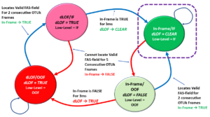
Figure 5, Drawing of the OTUk-dLOM Framing Alignment/Maintenance State Machine Diagram
Hence, Figure 5 shows that the OTUk-dLOM Framing Alignment/Maintenance State Machine diagram consists of four states.
- dLOM/LL-OOM State
- dLOM/LL-IM State
- In-Multiframe/LL-IM State
- In-Multiframe/LL-OOM State
The OTUk-dLOM Framing Alignment/Maintenance State Machine rides on top of the OTUk-MFAS OOM/IM State Machine. Therefore, we can think of the OTUk-dLOM Framing Alignment/Maintenance State Machine as an extension of this Low-Level State Machine.
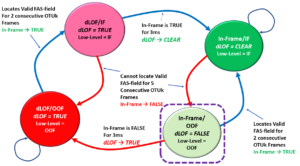
Hence, to illustrate that point, I have redrawn the OTUk-dLOM Framing Alignment/Maintenance State Machine diagram (that I show in Figure 5) to show the conditions that cause us to transition from one state to the next within the OTUk-MFAS OOF/IF State Machine. I show this redrawn figure below in Figure 6.
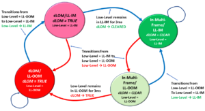
Figure 6, Illustration of the OTUk-dLOM Framing-Alignment/Maintenance State Machine Diagram (with OTUk-MFAS OOF/IF State Machine state change information shown).
The Sink STE will transition through each of the four states (within the OTUk-dLOM Framing Alignment/Maintenance State Machine) as it also transitions through the two states within the OTUk-MFAS OOM/IM Low-Level State Machine.
Whenever the System Operator powers up the Sink STE and starts receiving an OTUk data stream (once it has cleared the dLOF defect), it will continually operate in one of these four states. On occasion, the Sink STE will transition from one state to another. As it does this, it will declare or clear the dLOM defect, as shown in Figures 5 and 6.
We will now walk through the OTUk-dLOM Framing Alignment/Maintenace State Machine.
The dLOM/LL-OOM State
When the System Operator first powers up the Sink STE and is just starting to receive an OTUk data stream, the Sink STE will first clear the dLOF defect condition. Afterward, it will operate in the dLOM/LL-OOM State, as shown below in Figure 7.

Figure 7, Illustration of the OTUk-dLOM Framing Alignment/Maintenance State Machine Diagram with the dLOM/LL-OOM State Highlighted.
In the expression dLOM/LL-OOM, the reader should already know where the LL-OOM portion (of this state’s name) originates.
When we were discussing the OTUk-MFAS OOF/IF Low-Level State Machine (up above), we stated that whenever we first power up the Sink STE and it is just starting to receive an OTUk data-stream (and has cleared the dLOF defect condition), it will be operating in the LL-OOM state.
What does it mean to be in the dLOM/LL-OOM State?
The dLOM portion (of the expression dLOM/LL-OOM) means that the Sink STE is currently declaring the dLOM defect condition while operating in this particular state.
In summary, whenever the Sink STE is operating in the dLOM/LL-OOM state (within the OTUk-dLOM Framing Alignment/Maintenance State Machine), then we can state the following as fact:
- The Sink STE is operating in the LL-OOM State (within the Lower-Level state machine, as we discussed earlier) and
- The Sink STE is also declaring the dLOM defect condition (as the name of this state suggests).
Whenever the Sink STE operates in this state, it has NOT located the MFAS byte-fields within the incoming OTUk data stream. As far as the Sink STE is concerned, it only receives some stream of back-to-back OTUk frames. It cannot make sense of anything else within this data stream.
While the Sink STE operates in this state, it will parse through the incoming OTUk data stream and look for the MFAS byte-field.
Whenever the Sink STE has received (what it believes to be the MFAS byte because it immediately follows the FAS field), it will read in the contents of this “Candidate MFAS field.”
Next, the Sink STE will take that “Candidate MFAS field,” and it will insert that value into the following equation and compute a value for Next_Expected_MFAS_Value:
Next_Expected_MFAS_Value = MOD(Candidate_MFAS_Field + 1, 256)
Afterward, the Sink STE will wait an entire OTUk frame period (e.g., 16,320 bytes) later, and it will read out the contents of (what it believes is the MFAS byte). We will call this new byte value the “New_Candidate_MFAS_Value.”
Next, the Sink STE will compare that “New_Candidate_MFAS_Value” with its locally computed “Next_Expected_MFAS_Value,” by testing the following equation:
Next_Expected_MFAS_Value == New_Candidate_MFAS_Value;
If the New_Candidate_MFAS_Value fails the Test
If the Sink STE determines that the New_Candidate_MFAS_Value does NOT match the Next_Expected_MFAS_Value, then it has NOT located the MFAS byte. In this case, the Sink STE will continue to parse through (and search) the incoming OTUk data stream for another candidate MFAS byte.
It will also remain in the dLOM/LL-OOM state.
If the New_Candidate_MFAS_Value passes the Test
On the other hand, if the New_Candidate_MFAS_Value does (indeed) match the value for the Next_Expected_MFAS_Value, then the Sink STE will conclude that it has located the MFAS byte value. In this case, the Sink STE will transition from the LL-OOM state to the LL-IM state within the OTUk-MFAS OOM/IM State Machine.
As the Sink STE makes this transition within the low-level state machine, it will also transition from the dLOM/LL-OOM to the dLOM/LL-IM state within the OTUk-dLOM Framing Alignment/Maintenance State Machine.
The dLOM/LL-IM State
I illustrate the OTUk-dLOM Frame Alignment/Maintenance State-Machine diagram with the dLOM/LL-IM State highlighted below in Figure 8.

Figure 8, Illustration of the OTUk-dLOM Frame Alignment/Maintenance State-Machine Diagram, with the dLOM/LL-IM State highlighted
Whenever the Sink STE has transitioned into the dLOM/LL-IM State, we can state that the Sink STE has located (what appears to be) the MFAS-byte-field within the incoming OTUk data stream.
NOTES:
- We refer to this state as the dLOM/LL-IM state because the Sink STE is still declaring the dLOM defect condition (just as it was while operating in the dLOM/LL-OOM state). However, the “LL-IM” portion of the state’s name (e.g., dLOM/LL-IM) reflects the fact that the Sink STE has transitioned into the LL-IM (Low-Level In-Multi-frame) state within the lower-level state machine.
- I realize that calling this state the dLOM (Loss of Multi-Frame)/LL-IM (In-Multi-Frame) state is a bit of an oxymoron. In this case, the Sink STE is in-multi-frame because it has located the MFAS byte-field. However, it is still declaring the dLOM defect condition.
While the Sink STE is still operating in the dLOM/LL-IM state, it will perform the task of continuing to confirm whether or not it has located the MFAS byte (within the incoming OTUk data stream).
Whenever the Sink STE is operating in this state, two things can happen from here.
- It can eventually transition (or advance) into the “In-Multi-Frame/LL-IM” state, or
- It can transition (or regress) back into the dLOM/LL-OOM state.
We will discuss each of these possible events below.
Advancing to the In-Multi-Frame/LL-IM State
ITU-T G.798 requires that the Sink STE remain in the LL-IM state (at the low level) for at least 3ms before it can transition into the next state.
If the Sink STE remains in the dLOM/LL-IM state for at least 3ms (and continues to locate the MFAS byte accurately), then it will do all of the following:
- It will transition into the “In-Multi-Frame/LL-IM” state within the OTUk-dLOM Frame Alignment/Maintenance State Machine, and
- It will clear the dLOM defect condition (e.g., dLOM ⇒ 0).
I will discuss the In-Multi-Frame/LL-IM State later in this blog post.
Regressing to the dLOM/LL-OOM State
On the other hand, if the Sink STE (while in the dLOM/LL-IM state) were to lose synchronization with the MFAS byte, such that it cannot locate the MFAS byte for at least five (5) consecutive OTUk frame periods, then the Sink STE will transition back into the dLOM/LL-OOM state.
This means that the Sink STE will transition from the LL-IM state back into the LL-OOM state (at the Lower-Level State Machine).
Additionally, the Sink STE will continue to declare the dLOM defect condition.
The In-Multi-Frame/LL-IM State
Once the Sink STE has reached the In-Multi-frame/LL-IM state, we can say that it operates in the NORMAL (or intended) state. We expect the Sink STE to spend most of its operating lifetime in this state.
I show a drawing of the OTUk-dLOM Framing Alignment/Maintenance State Machine Diagram, with the In-Multi-frame/LL-IM State highlighted below in Figure 9.

Figure 9, Illustration of the OTUk-dLOM Framing Alignment/Maintenance State Machine Diagram, with the In-Multi-Frame/LL-IM State highlighted.
Whenever the Sink STE operates in the In-Multi-frame/LL-IM state, it can locate the MFAS byte-fields within each incoming OTUk frame.
What Does Clearing the dLOM Defect Mean?
Clearing the dLOM defect also means that the Sink STE should be ready to evaluate other aspects of this incoming OTUk data stream (which requires multi-frame alignment). This includes extracting the following types of data from the incoming OTUk/ODUk data stream.
- Within the OTUk Overhead
- SM-TTI (Trail Trace Identification) Messages
- Within the ODUk Overhead
- PM-TTI Messages
- APS/PCC Messages
- Within the OPUk Overhead
The MFAS byte is also critical for those applications where we are mapping and multiplexing lower-speed ODUj tributary signals into higher-speed ODUk server signals (where k > j).
Of course, the Sink STE is telling the whole world this fact by clearing the dLOM defect condition.
Whenever the Sink STE operates in the In-Multi-frame/LL-IM state, it is pretty tolerant of the occurrences of bit errors. In other words, if the Sink STE were to receive an OTUk frame, such that there was (for example) a single-bit error or even a burst of errors that affects an MFAS byte, the Sink STE would remain in the “In-Multi-frame/LL-IM” state.
On the other hand, if the Sink STE were to lose synchronization with the incoming OTUk data stream, such that it cannot locate valid MFAS bytes for five consecutive OTUk frames, then the Sink STE will transition from the LL-IM state into the LL-OOM state (within the Lower-Level State Machine).
Consequently, the Sink STE will transition from the In-Multi-frame/LL-IM state into the In-Multi-frame/LL-OOM state.
We discuss the In-Multi-frame/LL-OOM State below.
The In-Multi-frame/LL-OOM State
I show a drawing of the OTUk-dLOM Frame Alignment/Maintenance State Machine diagram with the In-Multi-frame/LL-OOM State highlighted below in Figure 10.

Figure 10, Drawing of the OTUk-dLOM Multi Frame Alignment/Maintenance State Machine diagram, with the In-Multiframe/LL-OOM State highlighted.
If the Sink STE transitions into the In-Multi-frame/LL-OOM state, this means the following things.
- The Sink STE has transitioned from the LL-IM state into the LL-OOM state within the OTUk-MFAS OOM/IM Low-Level State Machine.
- The Sink STE is still NOT declaring the dLOM (Loss of Multi-frame) defect condition (e.g., dLOM = 0).
NOTE: We refer to this state as the “In-Multi-frame/LL-OOM” state because the Sink STE is still NOT declaring the dLOM defect condition (just as it was NOT while operating in the In-Multi-frame/LL-IM state).
However, the LL-OOM portion of the state’s name (e.g., In-Multi-frame/LL-OOM) reflects that the Sink STE has transitioned into the LL-OOM state (within the Low-Level State Machine).
Only one of two possible things will happen whenever the Sink STE enters the In-Multi-frame/LL-OOM state.
- The Sink STE will eventually re-acquire synchronization with the incoming MFAS bytes (within the OTUk data-stream), and it will advance back into the In-Multi-frame/LL-IM state or
- The Sink STE does not re-acquire synchronization with the incoming MFAS bytes (within the OTUk data-stream), and it eventually regresses into the dLOM/LL-OOM state.
We will briefly discuss these two possible events below.
Advancing Back into the In-Multi-Frame/LL-IM State
If the Sink STE can locate and re-acquire the MFAS bytes (within the incoming OTUk data-stream), it will transition back into the In-Multi-Frame/LL-IM State. In this case, the Sink STE will continue to clear the dLOM defect condition (dLOM = 0).
Regressing to the dLOM/LL-OOM State
ITU-T G.798 requires that the Sink STE reside in the In-Multi-Frame/LL-OOM state for 3ms before it can transition into the dLOM/LL-OOM state and declare the dLOM defect condition.
This means that if the Sink STE cannot locate the MFAS-field (for 3ms after transitioning into the In-Multi-Frame/LL-OOM state), it will transition into the dLOM/LL-OOM state.
Whenever the Sink STE transitions into the dLOM/LL-OOM state, it will declare the dLOM defect condition (dLOM = 1).
In Summary
ITU-T G.798 requires that the Sink STE be able to locate the MFAS byte and consistently remain in the LL-IM state for at least 3ms before it can clear the dLOM defect condition (e.g., dLOM ⇒ CLEARED).
Further, ITU-T G.798 also requires that the Sink STE NOT be able to locate the MFAS byte and remain in this condition (e.g., the LL-OOM state) for at least 3ms before it can declare the dLOM defect condition (e.g., dLOM ⇒ DECLARED).
ITU-T G.798 imposes these 3ms persistency requirements (for declaring and clearing the dLOM defect) to prevent intermittent transitions between the LL-OOM and LL-IM states from causing sporadic changes (or chattering) in the dLOM state.
Table 1 summarizes the dLOM Defect Condition and how its State affects an OTN STE’s Operation.
Table 1, Summary of the dLOM Defect Condition and How its State affects an OTN STE’s Operation
| Item | Description |
| Meaning of the dLOM Defect Condition | The Sink STE (or OTSi/OTUk_A_Sk or OTSiG/OTUk_A_Sk atomic function) will declare the dLOM defect, if it has cleared the dAIS and the dLOF defect conditions, but it is not able to reliably locate the MFAS bytes and OTUk Multi-frame boundaries, within the incoming OTUk data-stream.
In other words, the Sink STE will declare the dLOM defect if it is able to find the FAS fields (within each incoming OTUk frame) but it still not able to reliably locate the MFAS bytes and align itself with each incoming 256-frame OTUk multi-frame. |
| Requirements to declare dLOM | The Sink STE (or OTSi/OTUk_A_Sk or OTSiG/OTUk_A_Sk atomic function) will declare the dLOM defect if it loses synchronization with the incoming MFAS bytes (and their increment value) for at least 3ms. |
| Requirements to clear dLOM | The Sink STE (or OTSi/OTUk_A_Sk or OTSiG/OTUk_A_Sk atomic function) will clear the dLOM defect if it is able to maintain synchronization with the incoming (and incrementing) MFAS byte-fields (within the OTUk data-stream) for at least 3ms. |
| Any defects that will suppress the dLOM defect? | Yes, the dAIS (OTUk-AIS) and dLOF defects. Or if upstream circuitry is declaring the Trail Signal Fail defect condition.
If the Sink STE (or OTSi/OTUk_A_Sk or OTSiG/OTUk_A_Sk atomic function) declares any of these defect conditions, then it cannot declare the dLOM defect. |
| Impact of declaring the dLOF defect on other defect conditions within the Sink STE | The Sink STE (or OTSi/OTUk_A_Sk or OTSiG/OTUk_A_Sk atomic function) should not declare any of the following defects, whenever it is also declaring the dLOM defect.
- dTIM, and
- dDEG |
| Impact of declaring the dLOM defect to Performance Monitoring. | None |
Clueless about OTN? We Can Help!! Click on the Banner Below to Learn More!!
Discounts Available for a Short Time!!

Click on the Image Below to see More OTN-Related Blog Posts.

OTN Related Topics within this Blog General Topics Consequent Equations - What are they and How can you use them? ...