

What is the ODUk-AIS Maintenance Signal, and How does a Network Element declare the dAIS Defect Condition?
What is the ODUk-AIS Maintenance signal?
AIS is an acronym for Alarm Indication Signal.
Another post describes the general purpose/role of the AIS maintenance signal.
For OTN applications, the Network Equipment (NE) will transmit the ODUk-AIS maintenance signal by overwriting the contents of an entire ODUk frame (e.g., ODU Overhead and Payload Data) with an All-Ones pattern.
NOTE: The variable k in the expression ODUk can be of any of the following values, depending upon the data rate: 0, 1, 2, 2e, 3, 4, and flex.
If an OTN STE were to map the ODUk-AIS Maintenance signal into an OTUk frame, then the OTN STE will be generating/transmitting a series of OTUk frames in which the FAS, MFAS, and OTUk Overhead fields are all valid.
The STE will compute and generate the FEC field based on the contents within these OTUk frames.
However, these OTUk frames will contain an ODUk Overhead, the OPUk Overhead, and the Payload fields that have been overwritten with an All-Ones pattern.
Figure 1 presents a drawing of an OTUk frame transporting the ODUk-AIS Maintenance signal.

Figure 1, Drawing of an OTUk frame carrying the ODUk-AIS Maintenance signal.
Please note that the ODUk-AIS pattern differs from the OTUk-AIS pattern (an Unframed PN-11 pattern).
What are the timing/frequency requirements for the ODUk-AIS Maintenance signal?
The OTN STE will need to transmit this ODUk-AIS Maintenance signal at the same nominal bit rate as an ordinary ODUk/OTUk signal.
Like any ordinary OTUk signal, the OTN NE will need to transmit this data at the nominal bit-rate ± 20ppm.
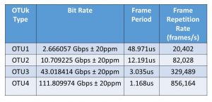
Table 1 presents the nominal bit-rates for the OTUk signals (and, in turn, for the OTUk signal, whenever it is transporting the ODUk-AIS indicator) for each value of k.
Table 1, Required Bit Rates for the OTUk signal – when transporting the ODUk-AIS signal.
When would OTN Network Equipment transmit/generate the ODUk-AIS Maintenance signal?
An OTN STE will generate/transmit the ODUk-AIS maintenance signal anytime it has detected and declared a service-affecting defect condition (at the OTUk-layer) within the upstream traffic.
For example: If an STE declares the dLOS-P (Loss of Signal – Path) or the dLOF (Loss of Frame) defect within its incoming OTUk signal, it will respond to this defect condition by transmitting the ODUk-AIS signal downstream.
Whenever the OTN STE transmits this ODUk-AIS maintenance signal downstream, it is (in effect) replacing the missing (or defective) ODUk signal (that the defective OTUk signal was transporting) with the ODUk-AIS maintenance signal.
In other words, the OTN STE will generate and transmit the ODUk-AIS Maintenance signal downstream rather than de-map out and transmit an ODUk signal that was likely destroyed by the service-affecting defect within its OTUk server signal. I show this phenomenon below in Figure 2.
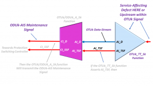
Figure 2, Drawing of OTN Circuitry transmitting the ODUk-AIS Maintenance Signal downstream, in response to a Service-Affecting Defect occurring within the OTUk-Layer, upstream.
The OTN STE will generate and transmit the ODUk-AIS maintenance signal towards downstream ODUk client equipment; anytime it declares any of the following service-affecting defects in the upstream signal.
- dLOS-P/dLOS-P[i] (Loss of Signal Defect)
- dLOFLANE[j] – Loss of Frame of Logical Lane – Logical Lane j
- dLOL – Loss of Lane Alignment
- dAIS (OTUk-AIS) Defect
- dLOF (Loss of Frame Defect)
- dLOM (Loss of Multframe Defect)
- dTIM (Trace Identifier Mismatch Defect)
Please see the post on AIS for an in-depth write-up on when the NE will (and will not) generate the AIS pattern downstream.
How does a Sink PTE detect and declare the ODUk-AIS (or dAIS) defect condition?
The Sink PTE downstream from the STE transmitting the ODUk-AIS Maintenance signal will detect and declare the ODUk-AIS defect condition whenever it receives a STAT field value of “1, 1, 1” within three (3) consecutive OTUk/ODUk frames.
NOTE: The STAT field is a 3-bit field that resides within the PM (Path Monitor) byte-field in the ODUk overhead.
The Upstream NE will set this 3-bit field to the value [1, 1, 1] because it overwrites the ODUk overhead with an All-Ones pattern whenever it transmits the ODUk-AIS Maintenance Signal.
Please see the ODUk Frame post for more information about the STAT field.
How does a Sink PTE clear the ODUk-AIS defect condition?
The Sink PTE will clear the ODUk-AIS defect condition whenever it has accepted a STAT field value of something other than “[1, 1, 1]”.
NOTE: The Sink PTE should accept a new STAT field value if it receives at least three (3) consecutive ODUk frames that contain a consistent STAT field value.
Inflation’s Got You Down? With our Pricing, We Can Help with Inflation and Make You an OTN Expert!! Click on the Banner Below to Learn More!!!
Discounts Temporarily Available!!

For More Information on OTN Posts in this Blog, click on the Image below.
