How Does a SONET Network Element Acquire Frame Synchronization with an incoming STS-1 Signal?

This blog post describes how the Receive STS-1 Framer uses the SEF/LOF Declaration Clearance State Machine diagram to acquire and maintain STS-1 Frame Synchronization.

Introduction

An STS-1 Network Element relies on the A1 and A2 bytes within the Section Overhead (SOH) to acquire and maintain STS-1 Frame Synchronization. 

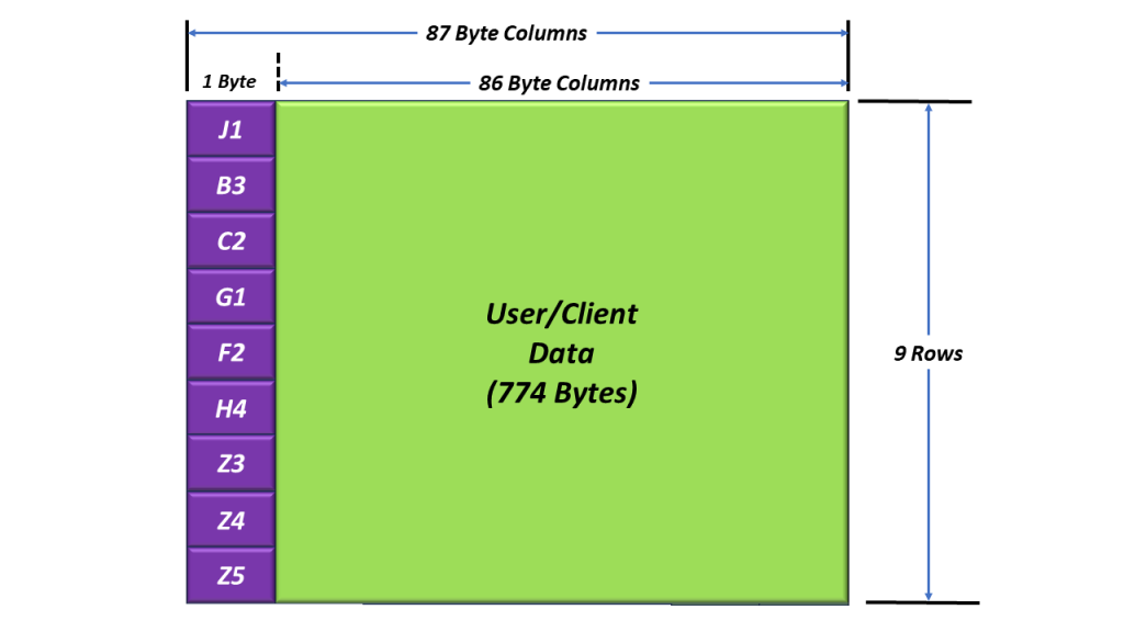
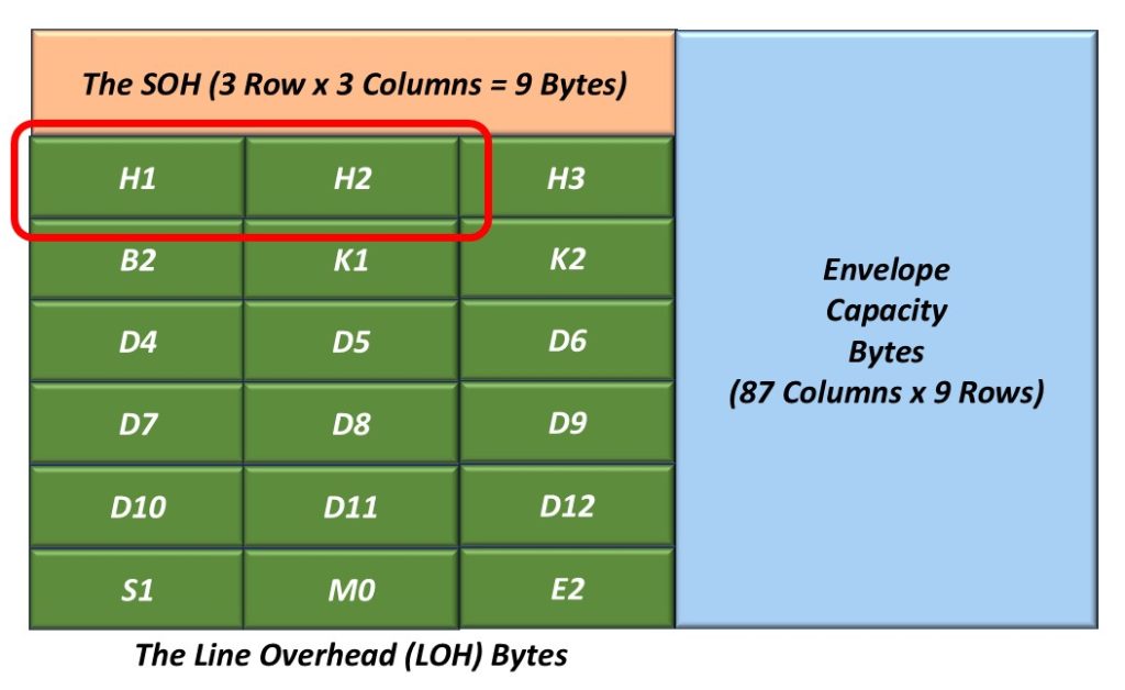
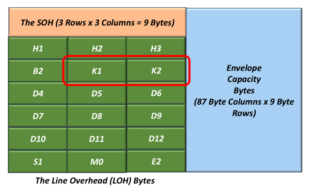
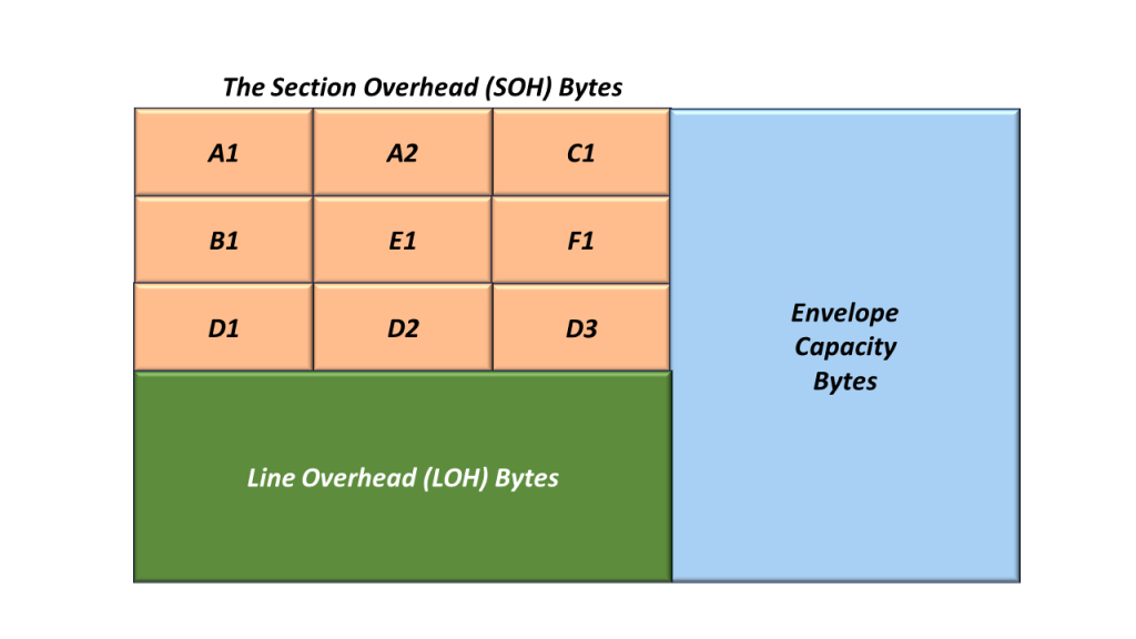
Figure 1 illustrates the Section Overhead bytes with the A1 and A2 bytes highlighted.

The STS-1 Section Overhead (SOH) Bytes within the A1 and A2 bytes highlighted

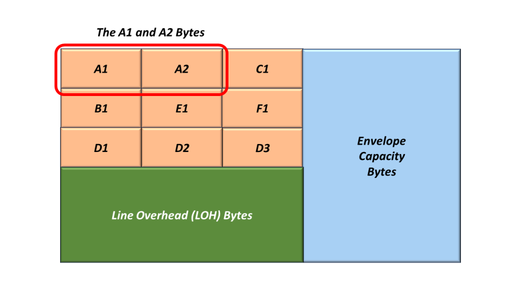
Figure 1, Illustration of the SOH with the A1 and A2 bytes highlighted. 

Whenever an STS-1 Transmitter (or STE) generates and transmits an STS-1 frame, it will always set the A1 and A2 bytes to the following values:

  • A1 = 0xF6
  • A2 = 0x28

I show an additional drawing of SOH, with the values for A1 and A2 filled in.

The SONET STS-1 Section Overhead (SOH) Bytes with values inserted into the A1 and A2 byte-fields

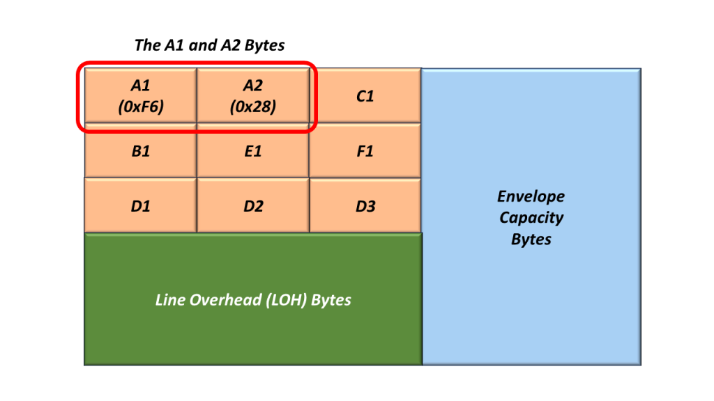
Figure 2, Illustration of the SOH with the A1 and A2 bytes set to their actual values.

Receive STS-1 Framer Tries to Acquire STS-1 Frame Synchronization

The Receive STS-1 Framer (at the remote end of the network – receiving this STS-1 signal) will search for and locate the A1 and A2 bytes (within its incoming STS-1 data stream). As the Receive STS-1 Framer receives this signal, it will attempt to acquire and maintain STS-1 Frame Synchronization with this incoming STS-1 data stream.

A given STE (receiving this STS-1 signal) will declare and clear either of the following defect conditions based on its ability to receive the A1 and A2 bytes.

  • dSEF – Severely Erred Frame Defect
  • dLOF – Loss of Frame Defect

The SEF/LOF Defect Declaration/Clearance State Machine

The decision to declare and clear the dSEF and/or dLOF Defects is best understood by reviewing the “SEF/LOF Defect Declaration/Clearance State Machine” Diagram. I show this diagram below in Figure 3. 

The SONET STS-1 Frame Acquisition State Machine Diagram.

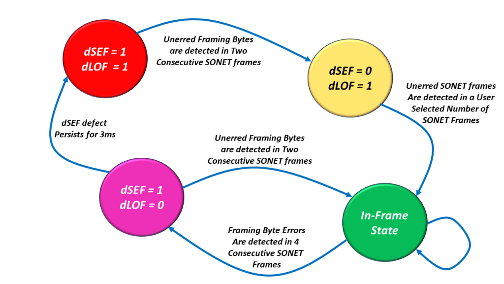
Figure 3, Illustration of the SEF/LOF Declaration/Clearance State Machine Diagram.

You can see that the “SEF/LOF Declaration/Clearance State Machine Diagram” contains the following four states.

  • The In-Frame (or SEF = 0/LOF = 0) State (the Most Desirable State to Operate in).
  • The SEF = 1/LOF = 0 State (Declaring the SEF – Severely Erred Frame defect condition).
  • The SEF = 1/LOF = 1 State (SONET Framer has not located the A1 and A2 bytes at all), and
  • The SEF = 0/LOF = 1 State (The SONET Framer has cleared the SEF defect and is now trying to clear the LOF defect condition).

Let’s Take a Walk through the SEF/LOF Declaration/Clearance State Machine Diagram

Let’s start at the “SEF = 1/LOF = 1” state.

The dSEF = 1/dLOF = 1 State

I show a drawing of the SEF/LOF Declaration/Clearance State Machine Diagram with the “SEF = 1/LOF = 1” state highlighted in Figure 4.

The SONET Framing State Machine Diagram wtih dSEF = dLOF = 1 State Highlighted.

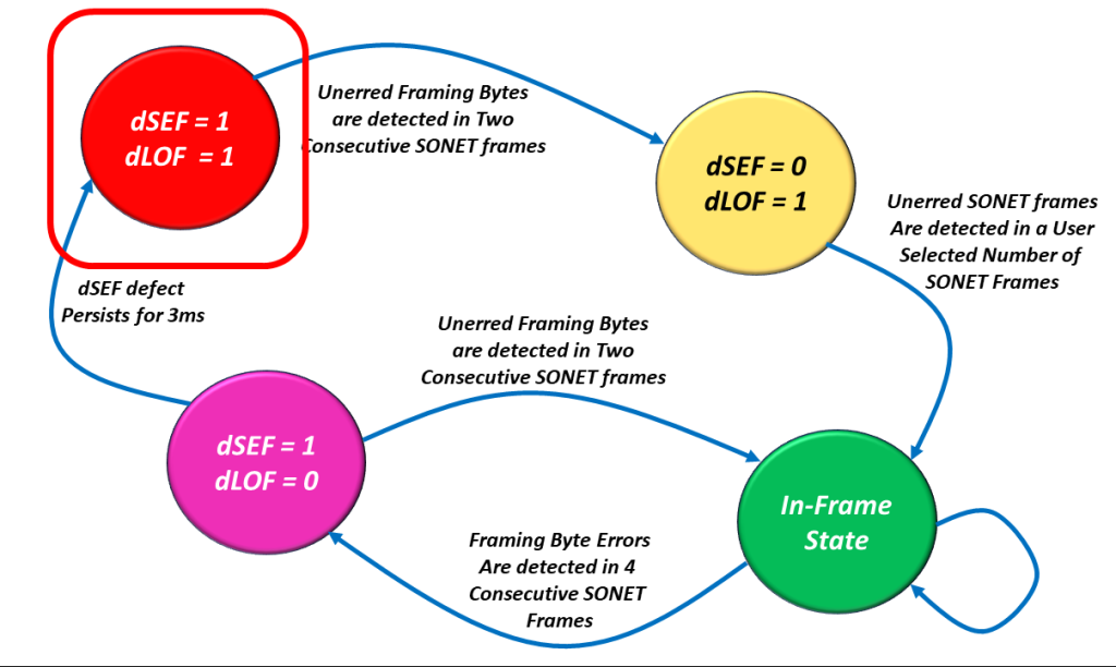
Figure 4, Illustration of the SEF/LOF Declaration/Clearance State Machine Diagram – with the SEF = 1/LOF = 1 state highlighted.

We hope the Receive STS-1 Framer is rarely operating in this state.

Let’s assume (and hope) that the Receive STS-1 Framer only operates in this state upon system power-up. Shortly after power-up, the Receive STS-1 Framer will operate in this state as it receives an STS-1 Data Stream.

As it receives this STS-1 Data Stream, it will parse this incoming data stream and search for the A1 and A2 bytes.

Once it locates (what it believes) are the A1 and A2 bytes (e.g., 0xF628), it will note this location, and it will search again exactly 810 bytes (e.g., one STS-1 frame period) later.

If it determines that the framing pattern (e.g., 0xF628) is NOT present, then the Receive STS-1 Framer will assume that it was momentarily fooled by data bytes mimicking the A1, A2 bytes.

On the other hand, if the Receive STS-1 Framer detects the framing alignment pattern again (exactly 810 bytes after finding it the first time), then it will “believe” that it is on to something and transition into the “dSEF = 0/dLOF = 1” state.

NOTE: In this case, the Framer will transition into the “dSEF = 0/dLOF = 1” state after the Framer has correctly detected the A1 and A2 bytes in two consecutive STS-1 frames.

The dSEF = 0/dLOF = 1 State

I show a drawing of the SEF/LOF Declaration/Clearance State Machine Diagram with the “dSEF = 0/dLOF = 1” state highlighted in Figure 5.

The SONET Framing State Machine Diagram with dSEF = 0, dLOF = 1 State Highlighted.

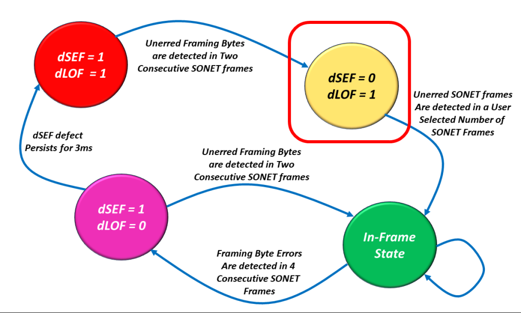
Figure 5, Illustration of the SEF/LOF Declaration/Clearance State Machine Diagram – with the dSEF = 0/dLOF = 1 state highlighted.

Once in this state, the Receive STS-1 Framer block will clear the dSEF (Severely Erred Frame) alarm. It will also continue to check the incoming A1 and A2 bytes for the Framing Pattern.

Telcordia GR-253-CORE states that “the SONET NE shall terminate a LOF defect 1ms to 3ms after terminating the SEF defect on the incoming SONET signal if the SEF defect is not (re) detected before the LOF defect is terminated.”

This is why we labeled the transition (from the “dSEF = 0/dLOF = 1” State to the “In-Frame” State) as “Unerred SONET Frames Are Detected in a User Number of SONET Frames“.

The user can select the criteria for clearing the dLOF defect to either be “1ms or 3ms” of Operating in the dSEF = 0 condition (with no re-declaration of the dSEF condition during that period).

Either way, if the SONET NE can meet these requirements, it will transition into the In-Frame State.

The In-Frame State

I show a drawing of the dSEF/dLOF Declaration/Clearance State Machine Diagram with the “In-Frame” state highlighted in Figure 6.

SONET Framing State Machiune Diagram with the In-Frame (dSEF = dLOF = 0) State Highlighted

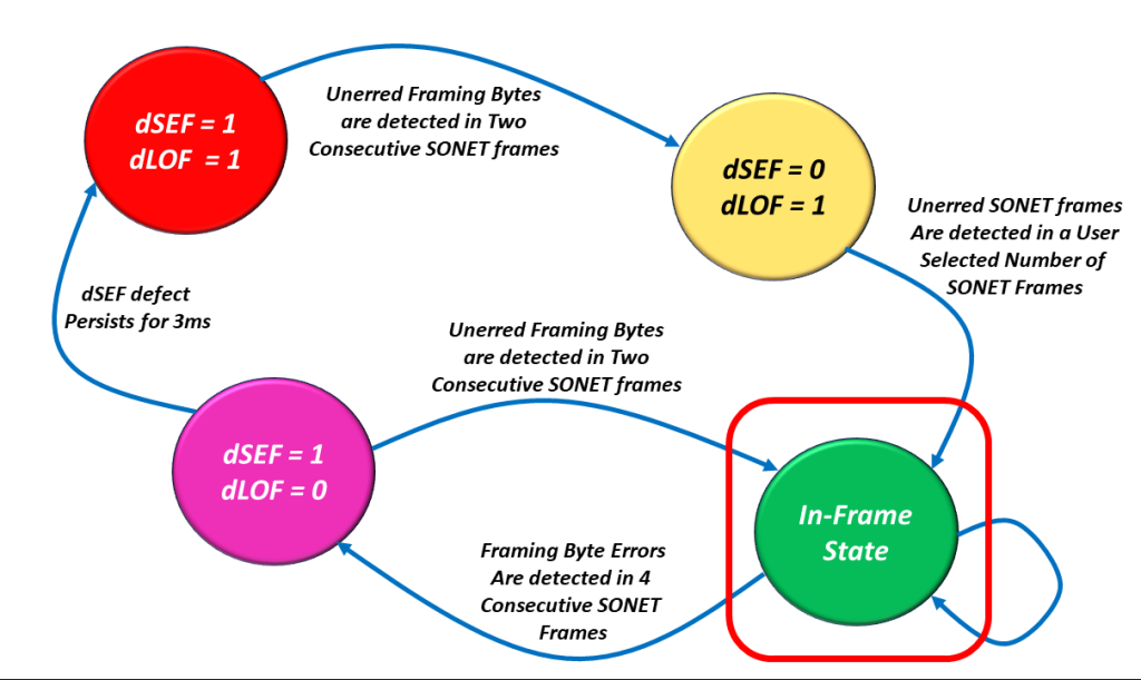
Figure 6, Illustration of the dSEF/dLOF Declaration/Clearance State Machine Diagram – with the In-Frame State Highlighted.

We hope that the Receive STS-1 Framer will operate in this state for most of its lifetime.

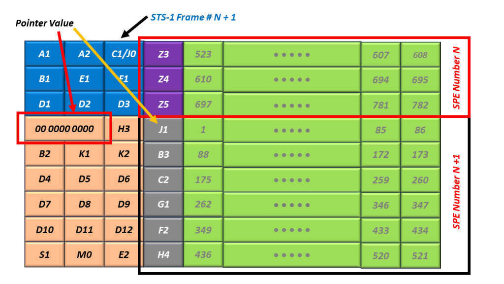
When the Receiver STS-1 Framer circuitry is operating in this state, the SONET NE can now do its other processing of STS-1 frames (checking for B1 bytes errors, using the H1 and H2 bytes to search for the SPE, etc.).

All of these things are possible whenever the Receiver STS-1 Framer is operating in this state. None of these things are possible if the Receiver STS-1 Framer is not operating in this state.

Is it possible for “Bad Things to Happen” such that We Have to Leave this State?

Yes, all good things “can and sometimes do come to an end.”

In other words, it is possible for “bad things to happen” that will cause the Receive STS-1 Framer to leave the “In-Frame” state.

If the Receive Framer were to detect FA1/FA2 errors within 4 consecutive STS-1 Frame, then it would declare the dSEF defect condition and transition into the “dSEF = 1/dLOF = 0” state.

The dSEF = 1/dLOF = 0 State

I show a drawing of the dSEF/dLOF Declaration/Clearance State Machine Diagram with the “dSEF = 1/dLOF = 0” state highlighted in Figure 7.

The SONET Framing State Machine Diagram with the dSEF = 1, dLOF = 0 State Highlighted.

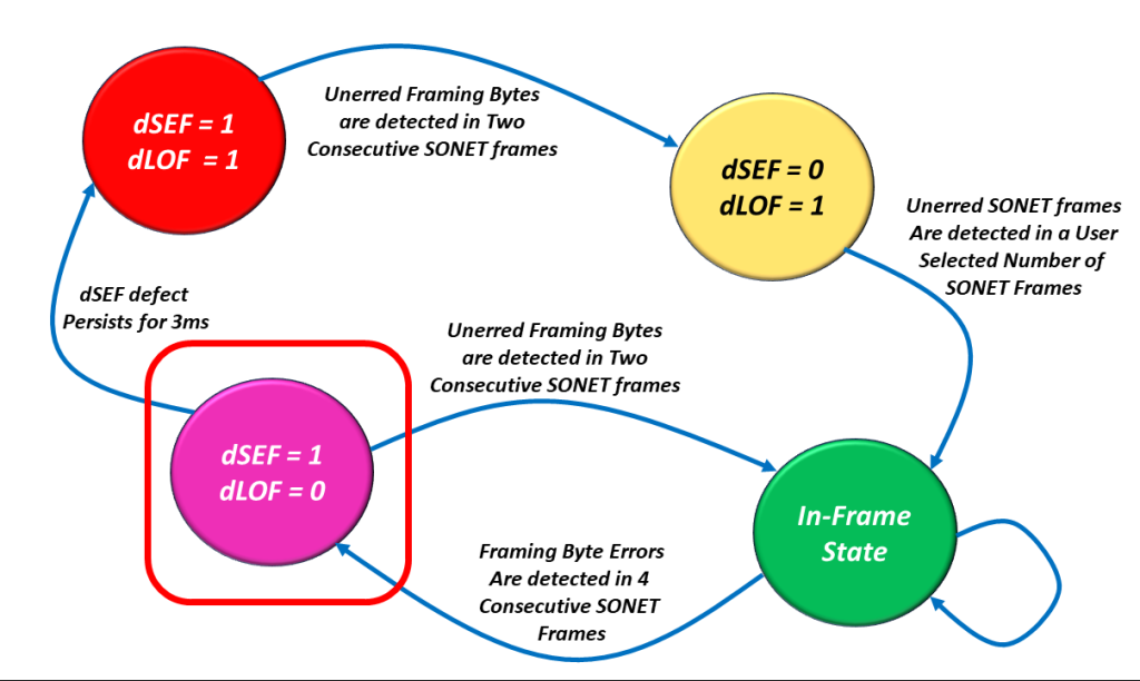
Figure 8, Illustration of the SEF/LOF Declaration/Clearance State Machine Diagram – with the SEF = 1/LOF = 0 State Highlighted.

If the Receive STS-1 Framer transitions into this state, then one of two things can happen from here.

The Good Option

The burst of errors could go away, and the Receive STS-1 Framer block could (then) detect two consecutive STS-1 Framers with NO FA1/FA2 byte errors.

If this occurs, the Receive STS-1 Framer block will clear the dSEF defect and transition back into the “In-Frame” state (the Good State). Once again, I show a drawing of the dSEF/dLOF Declaration/Clearance State Machine Diagram with the “In-Frame” state highlighted in Figure 9.

SONET Framing State Machiune Diagram with the In-Frame (dSEF = dLOF = 0) State Highlighted

Figure 9, Illustration of the dSEF/dLOF Declaration/Clearance State Machine Diagram – with the dSEF = 0/dLOF = 0 State Highlighted.

And there is the Bad Option.

The Bad Option

The burst of errors does not go away, and the Receive STS-1 Framer continues to operate continuously in the “dSEF Condition” for 3ms. When this occurs, then the Receive STS-1 Framer will declare the dLOF defect, and we will transition back into the “dSEF = 1/dLOF = 1” state.

In What States will the Receive STS-1 Framer declare the dLOF Defect Condition?

The Receive STS-1 Framer block will declare the dLOF defect condition whenever it is operating in the following two states:

  • dSEF = 1/dLOF = 1
  • dSEF = 0/dLOF = 1

In short, whenever dLOF = 1, then the Receive STS-1 Framer block declares the dLOF (Loss of Frame) defect condition.

In What States is the Receive STS-1 Framer NOT declaring the dLOF Defect Condition

The Receive STS-1 Framer block will clear the dLOF defect condition whenever it is operating in the following two states:

  • In-Frame
  • dSEF = 1/dLOF = 0

In short, whenever dLOF = 0, then the Receive STS-1 Framer clears the dLOF defect condition.

In Figure 10, I illustrate the SEF/LOF Declaration/Clearance State Machine Diagram, with two states immersed in “green shade” and the other two in “red shade.”

The SONET Framing State Machine Diagram - Shaded to Indicator which states in which the Framer declares and clears the LOF defect.

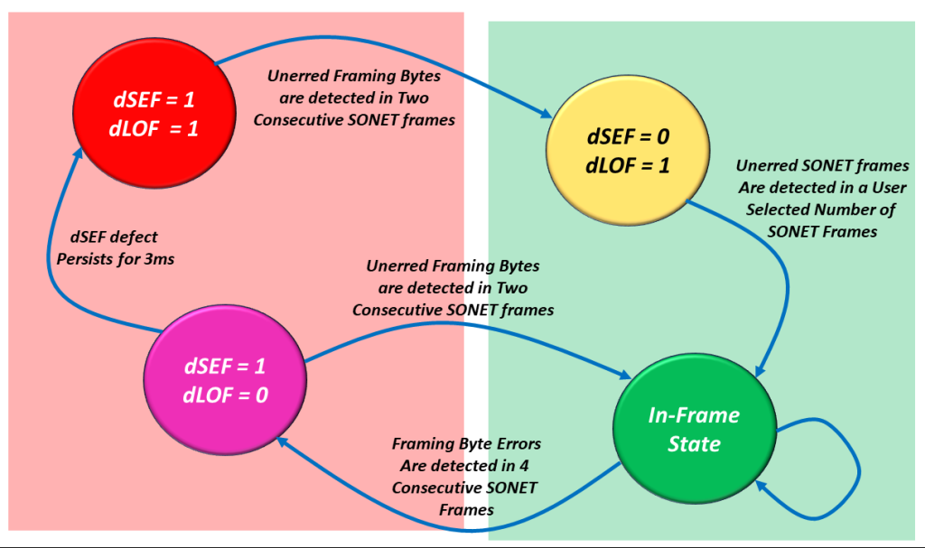
Figure 10, Illustration of the SEF/LOF Declaration/Clearance Machine Diagram – In which states will the Receive STS-1 Frramer declare or clear the dLOF defect condition.

The two states immersed in the Green Shade are those states in which the Receive STS-1 Framer will clear the dLOF defect condition.

On the other hand, the states immersed in the Red Shade are those states in which the Receive STS-1 Framer will declare the dLOF defect condition.

This concludes our introduction to the “SEF/LOF Declaration/Clearance” State Machine.

What is the Role/Function of the Path Overhead (POH) Bytes in a SONET Signal?

This blog post presents a brief description of the role/function of the Path Overhead (POH) Bytes.

What is the Purpose of the Path Layer in the SONET Network?

The purpose of the Path Layer is to support and manage the transport of “non-SONET” client data from the point where it gets mapped into a SONET signal to the point where it exits (or is de-mapped) from that same SONET signal.

Examples of non-SONET data being mapped into and transported via a SONET Network are DS1, E1, DS3, ATM, Ethernet, etc.

Each STS-N SPE consists of nine (9) Path Overhead bytes.

Figure 1 illustrates the Location of the Path Layer within our drawing of Optical Equipment.

Identifcation of the Path Layer within our SONET Reference Model.

Figure 1, Location/Identification of the Path Layer, within our drawing of Optical Equipment

What is Path Terminating Equipment (PTE)?

Any piece of equipment that manages the transmission and reception of non-SONET data, or client signal, from the point that it enters the SONET network to the point that the SONET Network is terminated (and the client signal is de-mapped from the SONET signal) is referred to as a PTE (Path Terminating Equipment).

A PTE will manage the transmission and reception of non-SONET client data (through the SONET network) via the “Path Overhead” (POH) bytes.

NOTE:  All PTEs are also LTEs and STEs.

Therefore, all PTEs will manage the transmission and reception of STS-N data via both the “SOH,” “TOH,” and “POH” bytes.

The POH bytes reside within the first column in the SPE (Synchronous Payload Envelope). 

In Figure 2, I show a picture of an SPE with the POH Bytes included.

The STS-1 Synchronous Payload Envelope (SPE)

Figure 2, Illustration of an SPE with the POH Bytes

The Definition of the Path Overhead (POH) Bytes

We will briefly define each of the POH bytes (within an SPE) below.

The J1 – Path Trace Byte

In Figure 3, I show a picture of the STS-1 SPE and POH with the J1 byte highlighted.

STS-1 Synchronous Payload Envelope with the J1 Byte Highlighted

Figure 3, Illustration of the STS-1 SPE and POH bytes, with the J1 Byte Highlighted

The J1 byte is the very first byte within the SPE.  This is also the byte that the H1 and H2 bytes (e.g., the Pointer Bytes) point to with an STS-N frame. 

For SONET applications, this byte is used to transport a repetitive 64-byte message so that the receiving Path Terminal Equipment (PTE) can verify its continued connection to the intended transmitting STS-N PTE.

NOTE:  For SDH applications, this byte can be used to transport a repetitive 16-byte message instead.

A given PTE will declare and clear the TIM-P (Path-Trace Identification Mismatch) defect condition. 

The TIM-P defect is typically an indication of a cross-connecting or provisioning error. 

I discuss the TIM-P defect condition in greater detail in another blog post.

B3 – Path BIP-8 Byte

Figure 4 presents the location of the B3 byte within the POH.

STS-1 Synchronous Payload Envelope with the B3 Byte Highlighted

Figure 4, The Location of the B3 Byte within the POH.

The Role of the Transmit PTE (in Handling the B3 Byte)

A Transmitting PTE will compute the contents of the B3 byte by performing a BIP-8 calculation over all bits within the POH and the SPE (after scrambling). 

This byte value is inserted into the B3 Byte field (within the very next outbound SPE) before scrambling the current STS-1 frame. 

The Role of the Receive PTE (in Handling the B3 Byte)
  • As a Receiving PTE receives its STS-1 SPE data stream, it will compute its own BIP-8 value. 
  • Afterward, the Receive PTE will compare its “locally” computed BIP-8 value with the value residing within the B3 byte field of the next STS-1 SPE.
  • If the two values are the same, then the Receive PTE will “conclude” that it has received this STS-1 SPE data in an un-erred manner.
  • If the two values are different, then the Receive PTE  will “conclude” that it received this STS-1 SPE in an erred manner. 
  • We discuss how SONET PTE should flag the occurrence of B3 byte errors in another blog post.

NOTES:

  1. The B3 byte (in SONET) is analogous to the Path BIP within an ODU Frame. 
  2. In another blog post, we will discuss how the Transmit PTE computes the B3 byte and how the Receive PTE Terminal verifies the B3 byte. 

C2 – Path Signal Label Byte

Figure 5 presents the location of the C2 byte within the POH.

STS-1 Synchronous Payload Envelope with the C2 Byte Highlighted

Figure 5, The Location of the C2 Byte within the POH.

The C2 (Payload Label) byte is used to indicate the content (or type of data) that is being carried within the SPE.

The C2 byte also includes the status of Mapped Payloads.

This byte can indicate the occurrence of defects within the data we are transporting via the SPE.

The C2 byte is analogous to the PSI (Payload Structure Identifier) Message that OPU frames transport in OTN. 

I describe the roles of the C2 byte in greater detail in another blog post.

G1 – Path Status Byte

Figure 6 presents the location of the G1 byte within the POH.

STS-1 Synchronous Payload Envelope with the G1 Byte Highlighted

Figure 6, The Location of the G1 Byte within the POH.

We use the G1 byte to transport the following alarm/defect conditions throughout the SONET Network.

  • REI-P (Path – Remote Error Indication)
  • RDI-P (Path – Remote Defect Indication)

I discuss the role of the G1 byte and the transport of the REI-P and RDI-P alarm/defect conditions in another post.

H4 Byte – Mapping Indicator Byte

Figure 7 presents the location of the H4 byte within the POH.

STS-1 Synchronous Payload Envelope with the H4 Byte Highlighted

Figure 7, Location of the H4 Byte within the POH.

The H4 Bye is defined for use as a “mapping-specific indicator” byte. Currently, the only applications that use the H4 byte involve VT-mapping and virtual concatenation.

We discuss how we use the H4 byte in VT-Mapping and Virtual Concatenation applications in other blog posts.

Z3 Byte – Undefined (For Future Use)

Z4 Byte – Undefined (For Future Use)

Z5 (or N1) Byte – STS Tandem Connection Monitoring

Figure 8 presents the location of the Z5 (N1) byte within the POH.

STS-1 Synchronous Payload Envelope with the Z5 or N1 Byte Highlighted

Figure 8, The Location of the Z5 (or N1) Byte within the POH.

We use the Z5 (or N1) byte to support TCM (Tandem Connection Monitoring) in the SONET Network.

We discuss using the N1 byte for Tandem Connection Monitoring in the SONET Network in another blog post. 

The STS-1 Envelope Capacity and Synchronous Payload Envelope

This blog post describes both the Envelope Capacity and the Synchronous Payload Envelope wtihin an STS-1 Frame.

In an earlier blog post, I showed a simple drawing of an STS-1 Frame.  In this drawing, I show the SOH (Section Overhead) and the LOH (Line Overhead).  I show this simple drawing again below in Figure 1.

Basic Structure of a SONET STS-1 Frame with Section Overhead (SOH) and Line Overhead (LOH)

Figure 1, Simplified Drawing of the STS-1 Frame. 

I have also briefly defined and discussed these byte fields in other posts. 

This blog post will briefly discuss the STS-1 Envelope Capacity and the Synchronous Payload Envelope. 

In Figure 1, you clearly see the Envelope Capacity within the STS-1 Frame.  It is clearly marked and takes up much of the STS-1 Frame. 

Where is the Synchronous Payload Envelope (SPE)?

Figure 1 also shows the SPE, but you don’t see it labeled in the Figure. 

What is the Purpose of the Envelope Capacity within the STS-1 Frame?

The purpose of the Envelope Capacity is to transport the client (or user) data. 

What is the Purpose of the SPE within the STS-1 Frame?

The purpose of the SPE is to transport the client (or user) data. 

So, the Envelope Capacity and the SPE have the exact same purpose.

Where is the SPE?

So, Where is the SPE?

The SPE and the Envelope Capacity are (sort of) one and the same.  The SPE has the same role/function as the Envelope Capacity. 

Further, the SPE is located within the Envelope Capacity.  And you can argue that the Envelope Capacity is located within the SPE. 

Location of the Envelope Capacity (within the STS-1 Frame)

The Envelope Capacity begins with the byte just to the right of the C1/J0 Byte (within the SOH).  I show the location of the first byte within the Envelope Capacity in Figure 2.

The 1st Byte within the Envelope Capacity Highlighted within an STS-1 Frame

Figure 2, Illustration of the Very First Byte within the Envelope Capacity

Figure 2 also shows that Byte 1 (the 2nd byte within the Envelope Capacity) is located just to the right of Byte 1, and so on. 

I show the Byte Numbering scheme for the Envelope Capacity below in Figure 3.

Byte Number within the Envelope Capacity of an STS-1 Frame

Figure 3, Byte-Numbering Scheme within the Envelope Capacity, within an STS-1 Frame (from Bytes 0 to Byte 782).

So, Where is the SPE?

The SPE is located in the exact same space as the Envelope Capacity.  However, its Byte Numbering Scheme is different. 

I show a drawing of the SPE below in Figure 4.

The STS-1 Synchronous Payload Envelope (SPE)

Figure 4, The SPE (Synchronous Payload Envelope)

Figure 4 shows the SPE (e.g., the Payload or User Data) along with the Nine Path Overhead (POH) bytes located in the left-most column (of the SPE).  This figure also shows that the STS-1 SPE is a 9 Row x 87 Byte Column Structure (the same size as the Envelope Capacity).

I discuss the role/function of the Path Overhead (or POH) bytes in another blog post

Figure 4 also shows that the very first byte of the SPE is the J1 byte (located in the upper left-hand corner of the SPE).  

What is the Byte-Numbering Scheme of the SPE within an STS-1 Frame

So, What is the Byte-Numbering Scheme of the SPE within an STS-1 Frame

The Byte-Numbering scheme differs for the STS-1 SPE from what we showed for the Envelope Capacity. 

In the case of the Envelope Capacity, Byte 0 is located just to the right of the C1/J0 byte (within the SOH), as I stated earlier.  Further, Byte 0 (within the Envelope Capacity is always in that same location (just East of the C1/J0 byte). 

In the case of the SPE, Byte 0 (e.g., the J1 byte) is located wherever the Pointer Bytes (H1 and H2) say that it is.  The H1 and H2 bytes permit the SONET Receiver to locate the SPE within the STS-1 frame.

The main difference between the SPE and the Envelope Capacity is that the location of the Envelope Capacity is fixed (Byte 0 is always located just East of the C1/J0 Byte). 

In the case of the SPE, Byte 0 (the J1 byte within the POH) can “float” anywhere within the Envelope Capacity. 

The Envelope Capacity and the SPE have the same roles and are of the same size (e.g., 783 bytes).  However, the location of the Envelope Capacity is fixed and aligned with the SOH and LOH bytes within the STS-1 Frame. 

The location of the SPE is not fixed (with respect to the SOH and LOH bytes) and can float. This means that the SPE can begin within any of the 783 bytes within the Envelope Capacity. 

I discuss the roles of the H1, H2, and H3 bytes and the location of the SPE (within the Envelope Capacity) in another blog post. 

However, in Figures 5, 6, 7, and 8, I show a couple of possible locations of the SPE (within the Envelope Capacity).

STS-1 SPE located at Pointer Location 00 0000 0000 within an STS-1 Frame - Frame 1 Shown

Figure 5, Illustration of the SPE, located at Byte 0 (just to the right of the H3 byte)STS-1 Frame N.

STS-1 SPE located at Pointer Location 00 0000 0000 within an STS-1 Frame - Frame 2 Shown

Figure 6, Illustration of the SPE (again located at Byte 0) – STS-1 Frame N+1.

In Figures 5 and 6, I also show that the pointer’s value (within the H1 and H2 bytes) is 0.  In this case, the SPE begins at Byte 0 (the Byte just to the right of the H3 byte).

Please note that the SPE will often straddle across two consecutive STS-1 frames. Figure 5 shows the location of the SPE within STS-1 Frame N. Further, Figure 6 shows the location of the same SPE within the next frame (STS-1 Frame N+1).

An STS-1 SPE located at Pointer Position Number 522.

Figure 7, Illustration of the SPE, located at Byte 522 (just to the right of the C1/J0 byte). 

In Figure 7, I show that the value of the H1 and H2 bytes are 522 (0x020A).  In this case, the SPE happens to be (accidentally) aligned with the SOH and LOF of the STS-1 Frame and located just to the right of the C1/J0 byte.

What Do the Pointer Values (within the H1 and H2 Bytes) Mean?

Finally, I show the Byte Numbering Scheme for SPEs in Figure 8.

What the H1 and H2 (Pointer Values) mean for the beginning of the STS-1 SPE.

Figure 8, What the Values of the H1 and H2 Bytes Mean – for the location of the J1 Byte within the SPE. 

In other words, Figure 8 presents the relationship between the value of the Pointers (within the H1 and H2 byte) and the location of the J1 Byte (within the SPE) within the STS-1 Frame.

Figure 8 shows that a Pointer Value of 0 corresponds with the STS-1 SPE starting at the byte, just to the right of the H3 Byte. I show an example of an SPE at this location in Figures 5 and 6.

This same figure also shows that a Pointer Value of 522 corresponds with the STS-1 SPE starting at the byte, just to the right of the C1/J0 byte. I show an example of an SPE at this location in Figure 7.

Why Don’t We Fix the Location of the SPE within the STS-1 Frame?

One important difference that the SPE has (from that of the Envelope Capacity) is that the location of the SPE can move from time to time. We refer to events (in which the SPE changes its location within the STS-1 Frame) as Pointer Adjustment events.

Whenever these Pointer Adjustment events occur, the values within the Pointer Bytes (e.g., the H1 and H2 bytes) will change. The SONET Network uses pointer adjustment to accommodate timing differences throughout the network.

I will discuss the H1, H2, H3 bytes, and Pointer Adjustments in another blog post.

What is the Role/Function of the Line Overhead (LOH) Bytes in a SONET Signal?

This blog post briefly describes/defines the roles/functions of the Line Overhead Bytes within a SONET signals.

The Line Layer

The Line Layer is the second highest layer within the SONET Reference Model.

The purpose of the Line Layer is to support the transmission of data between the Source and Sink Terminal of a given STS-N signal. 

Figure 1 presents an illustration of some STS-1 and STS-3 circuitry that helps to define the Line.

Illustration of a SONET Line. Also shows Sections, STEs and LTEs

Figure 1, Definition of an STS-N Line

In Figure 1, I show that an STS-3 Line Signal begins and ends at the STS-1 to the STS-3 MUX/DeMUX block (which originates and terminates the STS-3 signal).

What is an LTE – Line Terminating Equipment

Any piece of equipment that manages the transmission and reception of an STS-N data stream, from the point that we create this signal to the point where we terminate this signal.

An LTE will manage the transmission and reception of STS-N data via the Line Overhead (LOH) bytes.

The LOH bytes reside in (and are a subset of) what we often refer to as the “Transport Overhead” (TOH) bytes. Figure 2 illustrates the Line Overhead Bytes within an STS-1 Signal.

Illustration of the LOH (Line Overhead) Bytes within an STS-1 Frame

Figure 2, Illustration of the Line Overhead Bytes within an STS-1 Signal.

All LTEs are also STEs

Therefore, all LTEs will manage the transmission and reception of STS-N data via both the “SOH” and “LOH” bytes. 

We briefly define the SOH bytes (within an STS-1 frame) in another blog post.

Description of the Line Overhead (LOH) Bytes

H1 and H2 Pointer Bytes

Figure 3 highlights the location of the H1 and H2 bytes within the LOH.

The Line Overhead Bytes within an STS-1 signal with the H1 and H2 Bytes Highlighted

Figure 3, The Location of the H1 and H2 bytes within the LOH

The contents of the H1 and H2 bytes are used to indicate the offset between the location of these bytes and the first byte within the STS-1 Synchronous Payload Envelope (SPE).

An STS-1 Transmitter will compute a 10-bit pointer value and will insert this data into the H1 and H2 bytes within a given “outbound” STS-1 frame. 

An STS-1 Receiver will use this 10-bit pointer to locate the SPE within the incoming STS-1 data stream.

I present a more detailed discussion of the H1 and H2 bytes in another blog post.

H3 Pointer Action Byte

Figure 4 highlights the location of the H3 byte within the LOH.

The Line Overhead Bytes within an STS-1 signal with the H3 Bytes Highlighted

Figure 4, The Location of the H3 byte within the LOH.

We typically use the H3 byte for “Frequency” or “Pointer Justification” purposes.

I present a more detailed discussion of the H3 byte in another blog post.

The B2 Byte

Figure 5 presents the location of the B2 byte within the LOH.

The Line Overhead Bytes within an STS-1 signal with the B2 Byte Highlighted

Figure 5, The Location of the B2 Byte within the LOH.

The Role of the Transmit STS-1 Terminal

A Transmitting STS-1 Terminal will computer the contents of the B2 byte by performing a BIP-8 calculation over all bits within the LOH and the Envelope Capacity within a given “outbound” STS-1 frame (after scrambling). 

This byte value is inserted into the B2 Byte field (within the very next outbound STS-1 frame) before scrambling (of the current STS-1 frame).

The Role of the Receive STS-1 Terminal
  • As a Receiving STS-1 Terminal receives the LOH and the Envelope Capacity data (within a given STS-1 frame), it will compute its own BIP-8 value. 
  • Afterwards, the Receive STS-1 Terminal will compare the value of its “locally” computed BIP-8 value with the value residing within the B2 byte-field of the very next STS-1 frame.
  • If the two values are the same, then the Receive STS-1 Terminal will “conclude” that it has received the LOH and Envelope Capacity data in an un-erred manner.
  • If the two values are different, then the Receive STS-1 Terminal will “conclude” that it received the LOH and Envelope Capacity in an erred manner. 
  • We will discuss how SONET STEs should flag the occurrence of B2 byte errors in a future blog post.

NOTES:

  1. The B2 byte (in SONET) is analogous to the Section BIP within an OTU Frame. 
  2. We will discuss how the Transmit STS-1 Terminal computes the B2 byte and how the Receive STS-1 Terminal verifies the B2 byte in another blog post. 

The K1 and K2 (Automatic Protection Switching) Bytes

Figure 6 highlights the location of the K1 and K2 bytes within the LOH.

The Line Overhead Bytes within an STS-1 signal with the K1 and K2 Bytes Highlighted

Figure 6, The Location of the K1 and K2 Bytes within the LOH.

The SONET Protocol uses the K1 and K2 bytes for the following purposes:

  • To transport the APS signaling protocol (Used in BLSR and Linear APS schemes).
  • A given LTE will use the K1 and K2 bytes to detect/clear the following defect conditions within a SONET signal.
    • AIS-L (Line AIS) Defect
    • RDI-L (Line – Remote Defect Inidicator).

We will discuss the APS Protocol in another blog post. 

We will also discuss how the SONET Terminal transmits and declares the AIS-L and RDI-L defect conditions in another post. 

The Line Data Communication Channel (D4 through D12) Bytes

Figure 7 highlights the location of the Line Data Communication Channel Bytes within the LOH

The Line Overhead Bytes within an STS-1 signal with the Line Data Communication Channel (DCC) Bytes Highlighted

Figure 7, The Location of the Line DCC (Data Communication Channel) Bytes – D4 through D12 within the LOH

The D4 through D12 bytes are located in the first STS-1 of an STS-N and are considered as one 576kbps message-based channel for alarms, maintenance, control, monitoring and administering, and other communication needs. 

This channel is available for internally generated, externally generated, and supplier-specific messages.

I will discuss what I mean by the expression: “the first STS-1 of an STS-N” in another blog post. 

The S1 – Synchronization Status Byte

Figure 8 presents the location of the S1 Byte within the LOH.

The Line Overhead Bytes within an STS-1 signal with the S1 Byte Highlighted

Figure 8, Illustration of the LOH with the S1 Byte Highlighted

We use this byte to transport the Synchronization Status Message (SSM). 

I will discuss how we use the S1 byte in another blog post.

The M0 Byte – STS REI-L (Remote Error Indicator – Line)

Figure 9 presents the location of the M0 Byte within the LOH.

The Line Overhead Bytes within an STS-1 signal with the M0 Byte Highlighted

Figure 9, Location of the M0 Byte within the LOH.

The purpose of the M0 byte is to transmit the REI-L (Line – Remote Error Indicator) to a remote LTE. 

REI-L conveys the error count detected by the LTE (within the B2 byte) back to its peer LTE.

We will discuss the REI-L indicator and how we use it in another blog post. 

E2 Byte – Undefined

Figure 10 presents the location of the E2 byte within the LOH.

The Line Overhead Bytes within an STS-1 signal with the E2 Byte Highlighted

Figure 10, Location of the E2 Byte within the LOH.

What is the Role/Function of the Section Overhead (SOH) Bytes?

This blog post briefly defines the Section Overhead bytes within the SONET Frame.

The Section Layer and the Section Overhead (SOH) Bytes

The Section Layer involves transporting an STS-N data stream across the physical medium (e.g., copper or optical fiber) in a point-to-point manner (e.g., between any two adjacent pieces of equipment). 

The purpose of the Section Layer is to ensure that the STS-N data stream, which is being transported over a given link or coaxial cable or optical fiber, is properly received. 

Functions within this layer include:

  • Framing
  • Scrambling
  • Error detection
  • Section-Level Communications Overhead, such as the local orderwire.
  • Data Communication Channels (DCC) to carry information for OAM & P (Operation, Administration, Maintenance, and Performance). 

The Section Terminating Equipment (STE)

We refer to any piece of equipment that manages the transmission and reception of STS-N data over a single link of optical fiber or coaxial cable as an STE (Section Terminating Equipment).

An STE will manage the transmission and reception of STS-N data via the Section Overhead (SOH) bytes. 

The Section Overhead (SOH) Bytes

The SOH bytes reside in (and are a subset of) what we refer to as the “Transport Overhead” (TOH) bytes. 

Figure 1 illustrates the SONET Frame, with the SOH and LOH bytes field identified.

STS-1 Frame with the SOH (Section Overhead) and the LOH (Line Overhead) Shown

Figure 1, Another Look at the SONET Frame – SOH and LOH Bytes Highlighted.

I show and identify the Section Overhead (SOH) bytes in Figure 2 below.

Illustration of the SOH (Section Overhead) Bytes

Figure 2, Illustration and Identification of the Section Overhead Bytes

I will briefly describe the SOH bytes below.

The A1 and A2 (Framing Alignment) Bytes

In Figure 3, I show the location of the A1 and A2 bytes within the SOH. 

The STS-1 Section Overhead (SOH) Bytes within the A1 and A2 bytes highlighted

Figure 3, Location of the A1 and A2 Bytes within the Section Overhead

The A1 and A2 bytes are the Framing Alignment bytes.

These two bytes are assigned the following values:

  • A1 = 0xF6, and
  • A2 = 0x28

NOTE:  These values are the same as the FA1 and FA2 bytes within the OTU frame

A given STS-1 Transmitter will always set the A1 and A2 bytes to these specific values. 

The STS-1 Receiver (receiving this STS-1 signal) will search for and locate the “A1” and “A2” bytes to acquire and maintain STS-1 Frame Synchronization within this incoming STS-1 data stream.

A given STS-1 (receiving an STS-1 signal) will declare either of the following defect conditions based on its success in receiving the A1 and A2 bytes.

  • dSEF – Severely Erred Frame
  • dLOF – Loss of Frame

The STE will declare/clear the SEF and LOF Defect by using the “SEF/LOF Defect Declaration/Clearance – State Machine” diagram, which I show in Figure 4.

The SONET STS-1 Frame Acquisition State Machine Diagram.

Figure 4, Illustration of the SEF/LOF Declaration/Clearance State Machine Diagram

NOTE: We discuss the SEF/LOF Declaration/Clearance State Machine Diagram (and how the STE declares the dSEF or dLOF defect) in another blog post.

The C1 (STS-1 ID)/J0 (Section Trace Message) Byte

In Figure 5, I show the location of the C1 within the SOH. 

The SONET STS-1 Section Overhead (SOH) Bytes with the C1/J0 Bytes Highlighted.

Figure 5, Location of the C1/J0 Byte, within the Section Overhead

This Byte-Field serves two possible roles:

The C1 Byte (STS-1 ID)

In earlier editions of GR-253-CORE, the C1 byte was allocated to function as an “STS-1 ID” function. 

The C1 byte is no longer used for this purpose.

However, to ensure interoperability with older SONET equipment, this byte must be capable of transmitting and receiving the “STS-1 ID” number.

The J0 Byte – Section Trace Byte

The STE uses this byte to repetitively transmit a 1, 16, or 64-byte message so that the receiving STE can verify its continued connection to the intended transmitting sTS-1 STE. 

NOTE:  This is similar to the Trail Trace Identifier fields within the OTU and ODU frames. 

The B1 (Section BIP-8) Byte

In Figure 6, I present the location of the B1 byte within the STS-1 SOH.

The SONET STS-1 Section Overhead Bytes with the B1 Byte Highlighted

Figure 6, Location of the B1 Byte within the STS-1 SOH.

The Role of the Transmit STS-1 Terminal

A Transmitting STS-1 Terminal will computer the contents of the B1 byte by performing a BIP-8 calculation over all bits within a given “outbound” STS-1 frame (after scrambling). 

This byte value is inserted into the B1 Byte field (within the very next outbound STS-1 frame) before scrambling (of the current STS-1 frame).

The Role of the Receive STS-1 Terminal

  • As a Receiving STS-1 Terminal receives this STS-1 signal, it will compute its own BIP-8 value. 
  • Afterward, the Receive STS-1 Terminal will compare its “locally” computed BIP-8 value with the value residing within the B1 byte field of the next STS-1 frame.
  • If the two values are the same, then the Receive STS-1 Terminal will “conclude” that it has received this STS-1 signal in an un-erred manner.
  • If the two values are different, then the Receive STS-1 Terminal will “conclude” that it received this STS-1 signal in an erred manner. 
  • We will discuss how SONET STEs should check for and flag the occurrence of B1 byte errors in a future blog post.

NOTE:  The B1 byte (in SONET) is analogous to the Section BIP within an OTU Frame. 

The E1 (Orderwire) Byte

Figure 7 presents the location of the E1 byte within the STS-1 SOH.

The SONET STS-1 Section Overhead (SOH) with the E1 Byte Highlighted.

Figure 7, Location of the E1 Byte within the STS-1 SOH.

We refer to this byte as the Section Order-Wire Byte. 

The Standard Committee allocated this byte for use as a local order wire channel for voice communication between regenerators, hubs, and remote terminal locations.

The F1 (Section User Channel) Byte

Figure 8 presents the location of the F1 byte within the STS-1 SOH.

The SONET STS-1 Section Overhead (SOH) with the F1 Byte Highlighted.

Figure 8, Location of the F1 Byte within the STS-1 SOH.

The Standard Committee set aside the F1 byte for the user’s purposes. 

This byte is passed from STE to STE over the STS-N transmission media. 

This byte can typically be written into/read from at any STE.

Use of this byte is optional.

The D1, D2 and D3 (Section Layer – Data Communication Channel) Bytes

Figure 9 presents the location of the Section Layer Data Communication Channel (DCC) bytes within the STS-1 SOH.

The SONET STS-1 Frame with the Section Data Communication Channels (D1, D2, D3 Bytes) Highlighted.

Figure 9, Location of the Section Layer DCC Bytes within the STS-1 SOH.

These three bytes form a 192kbps message channel that supports transmitting OAM & P (Operation, Administration, Maintenance, and Provisioning) messages between pieces of Section Terminating Equipment.

ANSI.105.04 defines the protocols that we use in the Section Layer DCC.

Examples of STE (Section Terminating Equipment

Regenerators

Defects that occur within the Section Layer

  • dLOS – Loss of Signal
  • dSEF – Severely Erred Frame
  • dLOF – Loss of Frame

I briefly define and describe the Line Overhead Bytes (within a SONET Signal) in another blog post.

I also describe the Envelope Capacity and Synchronous Payload Envelope (SPE) in yet another blog post.

What is the SONET Reference Model?

This blog post defines the SONET Reference Model. It also describes some of the equipment that would support each of the Layers within the SONET Reference Model.

The SONET Reference Model

In the OSI (Open System International) Reference Model, we attempted to describe and understand a communications network via a seven (7) layer model.  This model consists of the following layers.

  • The Application Layer
  • The Presentation Layer
  • The Session Layer
  • The Transport Layer
  • The Network Layer
  • The Data Link Layer
  • The Physical Layer

In SONET, we attempt to describe and understand communication networks via a four (4) layer model (which we call the SONET Reference Model). 

In order of decreasing complexity, we have the following layers.

We will briefly describe each of these layers below.

In Figure 1, I show a drawing with some pieces of Optical Transmission Equipment.  I also show where each of these four SONET Layers fit in between these pieces of equipment.

SONET Reference Model - Section, Line and Path Layers

Figure 1, Illustration of the SONET Layers and Some Optical Equipment

We will now briefly describe some of these layers.

The Physical Layer

In SONET, the Physical Layer deals with the transport of bits across the transmission medium. 

There are no overhead bytes associated with the Physical Layer.

The main function of this layer is in the conversion between an STS-N digital data stream and either external optical or electrical SONET signals. 

Design issues associated with this layer typically include the following parameters:

  • Pulse Shape
  • Power Levels
  • Line Code
  • Timing
  • Connectivity

NOTE:  Optical Modules communicate at this layer.

The Section Layer

The Section Layer involves transporting an STS-N data stream across the physical medium (e.g., copper or optical fiber) in a point-to-point manner (e.g., between any two adjacent pieces of equipment). 

This layer aims to ensure that the STS-N data stream, transported over a given link, coaxial cable, or optical fiber, is properly received. 

Figure 2 presents a simple illustration of a Section.

Illustration of the Section and STE

Figure 2, Simple Illustration of a Section (a link between any two adjacent pieces of Equipment)

Functions within this layer include:

  • Framing
  • Scrambling
  • Error detection
  • Section-Level Communications Overhead, such as the local orderwire.
  • Data Communication Channels (DCC) to carry information for OAM & P (Operation, Administration, Maintenance, and Performance). 

What is Section Terminating Equipment (STE)

We refer to any piece of equipment that manages the transmission and reception of STS-N data over a single link of optical fiber or coaxial cable as an STE (Section Terminating Equipment).

An STE will manage the transmission and reception of STS-N data via the Section Overhead (SOH) bytes

The SOH bytes reside in (and are a subset of) what we refer to as the “Transport Overhead” (TOH) bytes. 

Figure 3 presents another look at the SONET Frame, with the TOH bytes field identified.

STS-1 Frame with the TOH (Transport Overhead) Shown

Figure 3, Another Look at the SONET Frame – TOH Bytes Highlighted.

I show (once again) that the TOH can be further divided into the SOH (Section Overhead) and Line Overhead (LOH) in Figure 4 below.

STS-1 Frame with the SOH (Section Overhead) and the LOH (Line Overhead) Shown

Figure 4 illustration the TOH being further divided into the SOH and LOH.

More about the SOH (Section Overhead Bytes)

As I mentioned earlier, we use the SOH (Section Overhead Bytes) to manage the transport of an STS-N signal across a Section.

Figure 5 presents a simple illustration of the 9 SOH bytes

Illustration of the SOH (Section Overhead) Bytes

Figure 5, Illustration of the Nine (9) SOH bytes

We discuss the function/role of the SOH bytes in another blog post.

The Line Layer

The Line Layer is the second highest layer within the SONET Reference Model.

The purpose of the Line Layer is to support the transmission of data between the Source and Sink Terminal of a given STS-N signal. 

The Line Layer is different from the Section Layer in that it (the Line Layer) will involve multiple pieces of electrical or optical transmission equipment. The Line Layer begins when we create a specific STS-N signal and ends when we terminate this STS-N signal.

The Section Layer only involves two adjacent pieces of electrical or optical transmission equipment.

Figure 6 presents an illustration of some STS-1 and STS-3 circuitry that helps to define the Line.

Illustration of a SONET Line. Also shows Sections, STEs and LTEs

Figure 6, Definition of an STS-N Line (or STS-3 Line)

In Figure 6, we define a “Line” as the circuitry and communication media from the point where we multiplex three STS-1 signals into an STS-3 to the point where we terminate the STS-3 signal and de-multiplex them back into the 3 STS-1 signals.

What is Line Terminating Equipment (LTE)

Any piece of equipment that manages the transmission and reception of an STS-N data-stream, from the point that we create this (STS-N) signal to the point where we terminate this (STS-N) signal.

An LTE will manage the transmission and reception of STS-N data via the Line Overhead (LOH) bytes.

The LOH bytes reside in (and are a subset of) what we often refer to as the “Transport Overhead” (TOH) bytes.

All LTEs are also STEs.

Therefore, all LTEs will manage the transmission and reception of STS-N data via both the “SOH” and “LOH” bytes. 

Figure 7 illustrates the LOH (Line Overhead) bytes within an STS-1 Frame.

Illustration of the LOH (Line Overhead) Bytes within an STS-1 Frame

Figure 7, Illustration of the LOH (Line Overhead) Bytes within an STS-1 Frame.

We discuss the function/role of the LOH (Line Overhead) bytes in another blog post.

The Path Layer

The purpose of the Path Layer is to support and manage the transport of “non-SONET” client data from the point where we map this client signal into the SONET network to the point where it exits (or is de-mapped) from the SONET network.

Examples of non-SONET data being mapped into and transported via a SONET Network are DS1, E1, DS3, ATM, Ethernet, etc.

Each STS-N SPE consists of nine (9) Path Overhead bytes.

Figure 8 illustrates the Location of the Path Layer within our drawing of Optical Equipment.

Identifcation of the Path Layer within our SONET Reference Model.

Figure 8, Location/Identification of the Path Layer, within our drawing of Optical Equipment

What is Path Terminating Equipment – PTE

Any piece of equipment that manages the transmission and reception of non-SONET data, or client signal, from the point that it enters the SONET network to the point that the SONET Network is terminated (and the client signal is de-mapped from the SONET signal) is referred to as a PTE (Path Terminating Equipment).

A PTE will manage the transmission and reception of non-SONET client data (through the SONET network) via the “Path Overhead” (POH) bytes.

The POH bytes reside within the first column in the SPE. 

Figure 9 illustrates the Synchronous Payload Envelope (SPE) with the Path Overhead (POH) Bytes.

Synchronous Payload Envelope (SPE) with the Path Overhead (POH) bytes

Figure 9, Illustration of the Synchronous Payload Envelope (SPE) with the Path Overhead (POH) Bytes.

NOTE:  All PTEs are also LTEs and STEs.

Therefore, all PTEs will manage the transmission and reception of STS-N data via both the “SOH,” “LOH,” and “POH” bytes.

I discuss the function/role of the Path Overhead (POH) bytes in another blog post.

Where is the Synchronous Payload Envelope?

In each of the figures above (e.g., Figures 3, 4, 5, and 7), I do not refer to the Synchronous Payload Envelope (SPE). I only refer to the Envelope Capacity (within the SONET Frame). I discuss the relationship between the Envelope Capacity and the SPE in another blog post.

What is SONET?

This blog post introduces the term SONET and briefly defines the Basic STS-1 frame in its most simplist of terms.

SONET is short for “Synchronous Optical NETwork.”

SONET is primarily a North American Standard.  The International (or the “Rest of the World”) version of SONET is called SDH, or Synchronous Digital Hierarchy.

SONET is an Optical Transport Standard that preceded OTN.  Just like OTN supports multiple data rates (e.g., OTU1, OTU2, etc.).  SONET supports a variety of rates, as I show below.

Table 1, List of Standard SONET and SDH Bit-Rates

SONET and SDH Bit Rate Table

Table 1 shows that the SONET/SDH Standards define bit rates up to almost 40Gbps.

This table also includes a column labeled STS-N Rates, where N can be integer numbers 1, 3, 12, 48, 192, and 768. We will talk a little bit about the STS-1 frame in this blog post. We will discuss STS-N frames and data rates in other blog posts.

What is the STS-1 Signal and Frame?

We will start this blog post by looking at the basic STS-1 Frame I show in Figure 1.

A Simple SONET STS-1 Frame with the Transport Overhead and Envelope Capacity shown

Figure 1, Illustration of the Basic STS-1 Frame (Simplified Drawing).

NOTE: STS stands for Synchronous Transport Signal.

The STS-1 frame consists of 9 rows and 90-byte columns (for a total of 810 bytes).

The frame repetition rate is 8000 frames/s.

Hence: 

90 bytes/row x 9 rows/frame x 8000 = 51.84Mbps (which matches the STS-1 data rate in Table 1).

Of these 810 bytes, we refer to 27 bytes as the Transport Overhead (TOH) bytes

We call the remaining 783 bytes the “Envelope Capacity.” 

NOTE: The Envelope Capacity (for an STS-1 frame) is large enough to carry the following:

  • 1 DS3 Signal
  • 28 DS1 Signals
  • 21 E1 Signals

Whenever we transport an STS-1 signal over a copper medium (such as a coaxial cable), we sometimes call this signal an EC-1 (Electrical Carrier – 1) signal. Likewise, whenever we transport an STS-1 signal over optical fiber, we can call it an OC-1 (Optical Carrier 1) signal

In other blog posts, we will show that we can further subdivide the TOH (Transport Overhead) within the STS-1 frame into the Section Overhead (SOH) and the Line Overhead (LOH).

Figure 2 shows that the basic STS-1 frame consists of 3 basic portions.

Basic Structure of a SONET STS-1 Frame with Section Overhead (SOH) and Line Overhead (LOH)

Figure 2, The SOH (Section Overhead), LOH (Line Overhead), and the Envelope Capacity within an STS-1 Frame.

In other blog posts, I will discuss the SOH, LOH, and Envelope Capacity in greater detail. 

I also present the SONET Reference Model in another blog post.

What is the RDI (Remote Defect Indicator)?

This post presents a generic definition of the term: RDI (Remote Defect Indicator) signal. It also describes how and when Network Equipment will transmit this type of signal.


What is the RDI (Remote Defect Indicator) Signal?

What does RDI Mean?

RDI is an acronym for Remote Defect Indicator.

Where is the RDI Signal Used?

RDI is a particular type of alarm signal that a Network Element (within a Telecom/Datacom application) will generate and transmit (back towards upstream Network Equipment) anytime it detects a servicing-affect defect within the signal from that same upstream Network Equipment.

Stated differently, the Network Element (NE) will transmit the RDI indicator (upstream) at the same time (and under the same conditions) that it will send the AIS signal downstream.

For example:  If an NE were to declare the LOS (Loss of Signal) or the LOF (Loss of Frame) defect within its incoming telecom/datacom signal, then it will respond to this defect condition by transmitting the RDI signal (back) upstream towards the source of the defective signal.

Whenever the Network Element transmits this RDI signal upstream, it notifies the upstream NE that there are problems with its data.

What EXACTLY is an RDI Signal?

The method we use to transmit the RDI signal depends upon the telecom/datacom standard and network layer we use.

However, in most cases, the Network Element will transmit the RDI signal by setting a certain overhead bit-field (within the signal it is transmitting back to the remote or upstream NE) to “1”.

The Network Element will continue to set this bit-field to “1” within each data frame (transmitting back to the remote NE) for as long as it declares the defect within its incoming data stream.

Likewise, once the Network Element clears the service-affecting defect, it will stop sending the RDI signal by clearing that same overhead bit-field to “0”.

For OTN applications, we call the RDI signal the BDI (or Backward Defect Indicator) signal.

I have included posts that describe the BDI signal for both the OTUk and ODUk frames.

For example, SONET Line-Terminating Equipment will transmit the RDI-L indicator, and SONET Path-Terminating Equipment will send the RDI-P indicator.

In the case of PDH signals (e.g., T1/E1 or T3/E3), we call the RDI signal by other synonymous names such as FERF (Far-End Receive Failure) or the “Yellow Alarm.

Clueless about OTN? We Can Help!! Click on the Banner Below to Learn More!!!

Discounts Available for a Short Time!!!

When do we transmit the RDI Signal?

We will use a couple of examples to illustrate how and when we transmit the RDI signal.

Example # 1 – The Unerred/Normal Condition

Figure 1 presents a simple illustration of a portion of a 3R Repeater/Regenerator, which consists of the following components:

  • Two (2) Receive Line Interface blocks (one block is labeled W for West, and the other block is labeled E for East)
  • Two (2) Receive Framer blocks (W – West and E – East)
  • Two (2) Transmit Line Interface blocks (W – West and E – East)
  • Two (2) Transmit Framer blocks (W – West and E – East)
  • CS (Clock Smoothing/Jitter Attenuation) PLL (Phase-Locked Loop)
  • AIS OSC (Stand-Alone Oscillator)
  • FIFO/Buffer
  • Two (2) Defect Decoder blocks (W – West and E – East)

In this figure, our 3R Repeater/Regenerator receives a good (error-free) signal from the West Terminal.

The 3R Repeater/Regenerator will first receive this signal through its Receive Line Interface (W) block.

Afterward, this signal passes through to the Receive Framer (W) block.

If the Receive Line Interface (W) and Receive Framer (W) blocks were to declare no problems within this signal.  The 3R Repeater/Regenerator would allow this signal to pass through both the Transmit Framer (E) and Transmit Line Interface (E) blocks as is.

The Receive Line Interface (W) and the Receive Framer (W) blocks would also do nothing to alter the data that the Near-End Transmitter circuitry (e.g., the Transmit Line Interface (W) and Transmit Framer (W) blocks) is transmitting back out to the West Terminal.

Figure 1 presents an illustration of this Normal (No Defect) Condition.

3R Repeater/Regenerator during Normal Conditions

Figure 1, Illustration of the 3R Repeater/Regenerator – during Good/Normal Conditions.

Please note that I have grayed out the non-relevant portions of Figure 1 to focus our discussion on this Defect Declaration to the RDI Generation mechanism on the West-side of the 3R Repeater/Regenerator circuit.

Let’s discuss the case where we will transmit the RDI indicator.

Example # 2 – The dLOS/Abnormal Condition

Figure 2 presents another simple illustration of a 3R Repeater/Regenerator.

However, in this figure, there is an impairment in the signal that originates from the West Terminal such that our Network Element is now declaring the dLOS (Loss of Signal) defect with this signal.

It is possible that a backhoe or some other mishap severed this signal.

Nonetheless, this means that our 3R Repeater/Regenerator is no longer receiving its signal from the West Terminal.

In this case, the 3R Repeater/Regenerator will respond by doing all the following:

  • The Receive Line Interface (W) or the Receive Framer (W) blocks will declare the dLOS (Loss of Signal) defect with the signal that it is receiving from the West Terminal.
  • The Transmit Framer (E) and the Transmit Line Interface (E) (which sit directly behind the Receive Line Interface and Framer blocks – that are declaring the dLOS condition) will now transmit the AIS indicator (to the East Terminal) as we discussed in the AIS post of this blog.
  • Additionally, the Receive Line Interface (W) and/or the Receiver Framer (W) blocks will also command its “near-end” transmitting circuitry [e.g., the Transmit Framer (W) and Transmit Line Interface (W) blocks] to start sending the RDI signal, back out to the West Terminal.

Figure 2 illustrates the dLOS/RDI Transmission Condition for our 3R Regenerator/Repeater.

3R Repeater/Regenerator when transmitting RDI

Figure 2, Illustration of the 3R Repeater/Regenerator – during the dLOS/Abnormal Condition

The Transmit Framer (W) and Transmit Line Interface (W) blocks will send the RDI indicator to the West Terminal for as long as the Receive Line Interface (W) and the Receive Framer (W) blocks declare the dLOS defect within the signal they are receiving from the West Terminal.

The Transmit Framer (W) and Transmit Line Interface (W) blocks will stop sending the RDI indicator once the Receive Line Interface (W) and the Receive Framer (W) blocks clear the dLOS defect and starts to receive good/normal data from the West Terminal.

In addition to the dLOS defect, the Network Element will transmit the RDI Indicator (upstream) in response to any other service-affecting defects, such as:

  • OTN Applications (Sending the SM-BDI or PM-BDI Indicator)
    • dLOF – Loss of Frame defect
    • dLOM – Loss of Multi-Frame defect
    • dLOFLANE – Loss of Frame defect for Logical Lane (for OTL3.4 or OTL4.4 applications)
    • dLOL – Loss of Lane Alignment defect (for OTL3.4 or OTL4.4 applications)
    • dLOFLOM – Loss of Frame and Multi-Frame defect (for Multiplexed Applications)
    • dLOOMFI – Loss of OMFI defect (for Multiplexed Applications using an ODU4 server signal)
    • dPLM – Payload Type Mismatch (for Multiplexed Applications)
    • dTIM – Trail Trace Identifier Mismatch defect

Please check out the appropriate blog posts to learn more about the SM-BDI or PM-BDI indicators for OTN applications.

Why do we bother to transmit the RDI Signal?

The main reason we send the RDI signal (back to upstream equipment) in response to service-affecting defects is to alert that NE that there is a service-affecting defect within its output signal between its location and that of the next downstream NE.

This notification aids in troubleshooting and system debugging of fault conditions in the network.

Inflation’s Got You Down? Our Discounts Can Help You Beat Inflation and Make You an Expert on OTN!! Click on the Banner Below to Learn More!!!

Discounts Available for a Short Time!!!

What is AIS (Alarm Indication Signal)?

This post defines and describes the AIS (Alarm Indication Signal). It also describes how and when Network Equipment will transmit this type of signal.


What is an AIS (Alarm Indication Signal)?

What does the term AIS Mean?

AIS is an acronym for Alarm Indication Signal.

Where is the AIS Signal Used?

The AIS signal is a particular type of alarm (or maintenance) signal that a Network Element (within a Telecom/Datacom application) will generate and transmit (in its downstream path) anytime it detects some service-affecting defect upstream.

For example:

Suppose a Network Element (NE) was to declare the LOS (Loss of Signal) or the LOF (Loss of Frame) defect within its incoming telecom/datacom signal. In that case, it will respond to this defect condition by transmitting the AIS signal downstream.

Whenever the Network Element transmits this AIS signal downstream, it is (in effect) replacing its defective incoming signal with the AIS signal.

What EXACTLY is an AIS signal?

The exact pattern/signature of an AIS signal depends upon the telecom/datacom standard and network layer we use.

For some datacom/telecom standards, the AIS signal is transmitted (and received) as an Unframed All One’s pattern.

In other standards, we will transmit the AIS indicator as a Framed All One’s pattern (e.g., where the framing alignment fields still use typical values, but the payload fields are filled with an All One’s pattern).

Finally, the OTUk AIS pattern is an Unframed PN-11 (PRBS11) pattern.

In all cases, the NE will generate and transmit the AIS signal at the nominal line rate (of the customarily transmitted signal).

The frequency accuracy requirements for this AIS signal also depend on the governing standards for the Telecom/Datacom system.

I have included posts that define the AIS patterns for OTUk and ODUk types of signals (for OTN applications).

When do we transmit the AIS pattern?

We will go through a couple of examples to illustrate how and when we will transmit the AIS signal.

Example # 1 – The Unerred/Normal Condition

Figure 1 presents a straightforward illustration of a portion of a 3R Repeater/Regenerator, which consists of the following components:

  • Two (2) Receive Line Interface blocks (one block is labeled W for West, and the other block is labeled E for East)
  • Two (2) Receive Framer blocks (W – West and E – East)
  • Two (2) Transmit Line Interface blocks (W – West and E – East)
  • Two (2) Transmit Framer blocks (W – West and E – East)
  • CS (Clock Smoothing/Jitter Attenuation) PLL (Phase-Locked Loop)
  • AIS OSC (Stand-Alone Oscillator).
  • FIFO/Buffer
  • Two (2) Defect Decoder blocks (W – West and E – East)

In this figure, our 3R Repeater/Regenerator receives a good (error-free) signal from the “West Terminal.”

The 3R Repeater/Regenerator will first receive this signal through its Receive Line Interface (W) block.

Afterward, this signal passes through to the Receive Framer (W) block.

Suppose the Receive Line Interface (W) and the Receive Framer (W) blocks were to detect no problems within this signal. In that case, the 3R Repeater/Regenerator will allow this signal to pass through the Transmit Framer (E) and Transmit Line Interface (E) blocks as is.

Our 3R Repeater/Regenerator will transmit this same data to the East Terminal.

Additionally, the Transmit Framer (E) and Transmit Line Interface (E) blocks would transmit the outbound data (towards the East Terminal) based upon the Recovered Clock signal (which originated from the West Terminal and has been routed through the Clock Smoothing PLL for Jitter Attenuation purposes).

Figure 1 presents an illustration of this Normal (No Defect) Condition.

Portion of 3R Repeater/Regenerator during Normal Operation

Figure 1, Illustration of the 3R Repeater/Regenerator – during Good/Normal Conditions.

Please note that I have grayed out the non-relevant portions of Figure 1 so we can focus our discussion on this Defect Declaration to AIS Generation mechanism in the West-to-East Terminal Path.

Now we will illustrate the case where we will transmit the AIS indicator.

Example # 2 – The dLOS/Abnormal Condition

Figure 2 presents another straightforward illustration of a 3R Repeater/Regenerator.

However, in this figure, there is an impairment in the signal that originates from the West Terminal such that our Network Element is now declaring the dLOS (Loss of Signal) defect with this signal.

It is possible that a backhoe or some other mishap severed this signal.

Nonetheless, our 3R Repeater/Regenerator is no longer receiving its signal from the West Terminal.

This also means that our 3R Repeater/Regenerator has no data to send to the East Terminal.

In this situation, our 3R Repeater/Regenerator will respond by doing the following things.

The Receive Line Interface (W) or the Receive Framer (W) blocks will declare the dLOS (Loss of Signal) defect with the signal that it is receiving from the West Terminal.

The Transmit Framer (E) and Transmit Line Interface (E) (which resides directly behind the Receiving Line Interface and Framer blocks – that are declaring the dLOS condition) will proceed to transmit the AIS indicator (to the East Terminal) as a replacement signal for the signal that we are no longer receiving from the West Terminal.

Additionally, the Transmit Framer (E) and Transmit Line Interface (E) blocks would transmit the AIS pattern (towards the East Terminal) based upon the output frequency of the AIS Oscillator (which is a stand-alone oscillator – that operates at the specified line-rate/clock frequency).

Figure 2 illustrates the dLOS/AIS Transmission Condition for our 3R Regenerator/Repeater.

3R Repeater/Regenerator declaring dLOS and transmitting AIS

Figure 2, Illustration of the 3R Repeater/Regenerator – during the dLOS/Abnormal Condition.

The Transmit Framer (E) and Transmit Line Interface (E) blocks will continue to transmit the AIS indicator to the East Terminal for the duration that the Receive Line Interface (W) and the Receive Framer (W) blocks are declaring the dLOS defect with the signal that they are receiving from the West Terminal.

The Transmit Framer (E) and Transmit Line Interface (E) blocks will cease to transmit the AIS indicator once the Receive Line Interface (W) and the Receive Framer (W) blocks clear the dLOS defect and start to receive good/normal data from the West Terminal.

At this point, the Transmit Framer (E) and Transmit Line Interface (E) blocks will transmit good/normal data to the East Terminal.

In addition to the dLOS defect, the Network Element will typically transmit the AIS indicator (downstream) in response to the following other defects.

  • dLOF (Loss of Frame Defect)
  • dLOM (Loss of Multi-Frame Defect)
  • dLOFLANE (Loss of Frame of Logical Lane) – for OTL3.4 or OTL4.4 applications (*)
  • dLOL (Loss of Lane Alignment) – for OTL3.4 or  OTL4.4 applications (*)
  • dTIM (Trail Trace Identifier Mismatch)

(*) – Need to be a member of THE BEST DARN OTN TRAINING PRESENTATION…PERIOD!!! to access these links.

Why do we bother to transmit the AIS signal as a replacement signal?

We transmit the AIS indicator downstream in response to service-affecting defects for several reasons.

I will list some of those reasons below.

  • Alerts downstream equipment that we have detected and declared a service-affect defect upstream.
  • To suppress (or prevent) the downstream equipment from declaring their service-affecting defect.
  • Aids in troubleshooting and system debugging. It is easier to isolate the causes of defect conditions if we know exactly which NE is declaring the defect and not the whole chain of NEs downstream.
  • The downstream Receive Circuitry provides a much-needed clock signal at the correct bit rate. Clock Recovery PLLs (Phase-Locked-Loops) and Bias Controllers (for Optical Receive circuitry) all need upstream NEs to provide them with a line signal with the appropriate timing (bit-rate).

The AIS signal accomplishes these goals.

Has Inflation got You Down? Our Price Discounts Can Help You Fight Inflation and Help You Become an Expert on OTN!! Click on the Banner Below to Learn More!!!

Discount Available Temporarily

The AMP (Asynchronous Mapping Procedure)

This post discusses and describes the AMP (Asynchronous Mapping Procedure) that one can use to map client signals into OTN signals and transport them through the Optical Transport Network (OTN).

What is the AMP (Asynchronous Mapping Procedure)?

This post describes the AMP (Asynchronous Mapping Procedure) for mapping a non-OTN CBR (Constant Bit Rate) client signal into an OPUk/ODUk signal.

ITU-T G.709 also states that the system designer can use AMP to map lower-speed ODUj tributary signals into a higher-speed OPUk server signal.  We will discuss that topic in another post.

NOTE:  Whenever ITU-T G.709 discusses procedures for mapping a CBR client signal into an OPUk/ODUk signal, it will often refer to the OPUk/ODUk signal as the Server signal.  We will use the terms OPUk/ODUk and Server interchangeably throughout the rest of this post.

ITU-T G.709 also defines two other mapping procedures that one can use to map a non-OTN CBR client signal into a Server signal.

We discuss each of these two mapping procedures in other posts.

(*) – Requires membership to THE BEST DARN OTN TRAINING PRESENTATION…PERIOD!!!  to see this post.  

What is the Asynchronous Mapping Procedure?

The name Asynchronous Mapping Procedure means that the timing relationship between the client signal (being mapped into an OPUk payload) and the bit-rate of the OPUk payload are close in frequency but still asynchronous.

This timing relationship is different from that for the BMP (Bit-Synchronous Mapping Procedure).

In BMP, the timing relationship between the Client Signal and the Server signal must be synchronized.  For AMP, we can say (in a “tongue-in-cheek manner”) that the timing relationship between the Client Signal and the Server signal is “close, but no cigar”!!  I’ll explain that comment below.

The System Designer must ensure that ALL the following is true before they can use the Asynchronous Mapping Procedure to map a non-OTN client signal into the OPUk payload.

  • The Client signal clock frequency must be within ±65pm of the OPUk Payload clock frequency.
  • The System-Designer must handle Rate differences (between the Client and the Server signal) via fixed and variable stuffing.
  • This ±65ppm tolerance accounts for the maximum variable stuffing (justification) limits.

How AMP Works

We begin our discussion of AMP by looking at the OPUk Overhead bytes.

In Figure 1, I illustrate the OPUk Frame (within the OTUk Frame).

OTUk Frame with OPUk Portion shown

Figure 1, Illustration of the OPUk Frame – within the OTUk Frame.

In Figure 2, I take a closer look at the OPUk frame structure and show a more detailed drawing of the OPUk Overhead Bytes within the OPUk Frame.

AMP Discussion - Basic Figure - Introduction of OPUk OH

Figure 2, Illustration of the OPUk Overhead Bytes – for AMP Applications

This figure shows five (5) Overhead Bytes that play a role in AMP.

  • JC1 – Justification Control Byte # 1
  • JC2 – Justification Control Byte # 2
  • JC3 – Justification Control Byte # 3
  • NJO – Negative Justification Opportunity Byte
  • PJO – Positive Justification Opportunity Byte

Figure 2 also shows the bit format for the three Justification Control Bytes.  This figure shows that Bits 1 through 6 (within each of these 3 bytes) are labeled RES (Reserved) and do not have a role in AMP.

This figure also shows Bits 7 and 8 (within these 3 bytes), which we have labeled JC7 and JC8, do have a role in AMP.

Has Inflation got You Down? Our Price Discounts Can Help You Fight Inflation and Become an Expert on OTN!!! Click on the Banner Below to Learn More!!!

Discount Available for a Short Time!!!

Justification Events within an OPU Frame

We earlier stated that if the System Designer wishes to use AMP to map a non-OTN client signal into an OPUk frame, then they must make sure that the frequency differences between the client signal and that for the OPUk payload are within ±65ppm.

Since there is no requirement to phase-lock the OPUk Payload frequency to the client signal frequency (as ITU-T G.709 requires for BMP applications), it is unlikely that these two signals will be at the same rate.  

They will, most likely, be close (in frequency) to each other but off in one direction or the other.

In this case, the Source (OTN) Path Terminating Equipment (PTE) will generate many of its OPUk frames with no justification events.  But, because these two signal frequencies will typically not be identical, the Source PTE will eventually generate OPUk frames with justification events.  We sometimes call these justification events slip events in other forms of data communication.

NOTE:  These justification events are also similar to the pointer justification events in SONET/SDH Networks.

The Source PTE will use these Justification Events to compensate for the frequency differences between the Client and the server signal.  

Please see the post on “slip events” to understand the mechanics of slip events (e.g., why they occur and how we can elegantly handle them).

A Source PTE can generate three (3) types of OPUk frames in AMP.

  • OPUk frames with NO Justification Events (e.g., The Nominal Condition)
  • OPUk frames with Negative-Justification events (occurs periodically if the Client Bit Rate > OPUk Bit Rate)
  • OPUk frames with Positive-Justification events (appears regularly, if the Client Bit Rate < OPUk Bit Rate)

We will discuss each of these types of OPUk frames below.

The Normal Situation – The Source PTE creates an OPUk Frame with No Justification Activities.

Many of the OPUk frames that a Source PTE generates will belong to this category for AMP applications.

Figure 3 shows a drawing of an OPUk Frame, with NO Justification events occurring.

OPUk Frame - AMP Discussion - No Justification Event


Figure 3, An Illustration of an OPUk Frame with NO Justification events occurring

This figure shows that this OPUk frame does NOT have a Justification Event by:

  • Setting at least two (out of the three) sets of JC7 and JC8 bit-fields to [0, 0] as shown above.
  • The PJO byte field is currently carrying a client data byte (as it usually does) – in this OPUk frame.
  • The NJO byte field is NOT transporting a client data byte but is (instead) carrying a stuff byte (which is also a nominal condition).

The settings within the JC7 and JC8 bit-fields alert the Sink PTE (at the other end of the network) that there is no justification event occurring within this OPUk frame and:

  • That the PJO byte-field is currently carrying client data, and
  • The NJO byte field is transporting a stuff-byte (and is NOT transporting client data).

NOTE:  If (by design or accident) the OPUk payload rate is equivalent to the Client bit-rate, then the Source PTE will ALWAYS generate these types of OPUk frames (e.g., with NO Justification Events). 

If the System Designer has achieved this synchronous relationship (between the OPUk and the Client signal) by design, this becomes Bit-Synchronous Mapping (BMP).

Negative Stuff Event (Occurs if the Client Bit Rate > OPUk Bit Rate)

If the Client-data bit rate is slightly faster than that for the OPUk payload rate, then (with no intervention) the Mapper Buffer will eventually fill up.

AMP uses Negative-Stuffing (or Negative Justification) to prevent the Mapper buffer from Overflowing.  

In this case, the Source PTE will (temporarily) increase our Server (OPUk) signal’s bandwidth (to pull additional data out of the Mapper Buffer) by forcing both the PJO and the NJO bytes to carry client data momentarily.

Hence, for systems in which the Client data bit rate is faster than the OPUk payload bit rate, the Source PTE will periodically need to generate OPUk frames with Negative Justification to keep the Mapper Buffer from filling up.

Figure 4 shows a drawing of such an OPUk frame.

OPUk AMP Discussion - Negative Justification


Figure 4, Illustration of an OPUk Frame with Negative Justification occurring

This figure shows that this OPUk frame has a Negative Justification Event by setting at least two (of the three) sets of JC7 and JC8 bits to [0, 1], as I show above.  

The Source PTE will also (for this particular OPUk frame) use both the NJO and the PJO byte fields to carry client data bytes.

When the Source PTE sets the JC7 and JC8 bit-fields to these values, it notifies the Sink PTE (at the remote end of the network) of the roles of the NJO and PJO bytes within this OPUk frame.

NOTES:

  1. For the NO Justification OPUk frames, the NJO byte is considered part of the OPUk Overhead and usually does not transport any client data.  For Negative Justification OPUk frames, the NJO byte will (for this OPUk frame) be carrying client data.
  2. If the Client-data bit rate is faster than the OPUk Payload rate, then the PJO byte will ALWAYS carry client data (in every OPUk frame).  In this case, we will sometimes use the NJO byte to transport client data (within OPUk frames with justification events).

Positive Stuff Event (Occurs if the Client Bit Rate < OPUk Bit Rate)

If the Client-data bit-rate is slightly slower than that for the OPUk Payload rate, then (with no intervention) the Mapper Buffer will eventually be depleted.

AMP uses Positive-Stuffing (or Positive Justification) to avoid depleting the Mapper buffer.  

In this case, the Source PTE will temporarily reduce the Server signal’s (e.g., the OPUk signal) bandwidth (for this OPUk frame) by forcing both the PJO and the NJO bytes to transport stuff (and NOT client) data.

Hence, for designs in which the Client data bit rate is slower than the OPUk payload, the Source PTE will periodically generate OPUk frames with Positive Justification to avoid depleting the Mapper Buffer.

NOTE:  For the NO Justification OPUk Frames, the PJO byte field will be carrying client data.  But, during Positive Justification frames, the PJO byte will transport a stuff (or dummy) byte instead.  In other words, the Positive Justification OPUk frame will not carry client data within the PJO byte-field. 

This action momentarily slows the rate at which the Server pulls data out of the Mapper Buffer and keeps the buffer from depleting.

Figure 5 shows a drawing of an OPUk frame with Positive Justification occurring.

OPUK Frame - AMP Discussion - Positive Justification Frame


Figure 5, Illustration of an OPUk Frame with Positive Justification occurring

This figure shows that this OPUk frame has a Positive Justification event by setting at least two (of the three) sets of JC7 and JC8 bits to “[1, 1].

When the Source PTE sets the JC7 and JC8 bit-fields to these values, it notifies the Sink PTE (at the remote end of the network) of the roles of the NJO and PJO bytes within this OPUk frame.

NOTE:  If the Client data rate is slower than the OPUk Payload rate, then the NJO byte will ALWAYS function as a stuff byte (e.g., never carrying client data), and the PJO will sometimes function as a stuff byte (during OPUk frames with justification events).

Interpreting the JC7 and JC8 Bits

Table 1 summarizes how to understand the JC7 and JC8 bits (within two out of the three Justification Bytes) and the corresponding roles for the NJO and PJO bytes within the OPUk Frame.

Table 1, How to Interpret the Settings of the JC7 and JC8 bits within Two (of the Three) Justification Bytes, and the corresponding roles for the NJO and PJO bytes within the OPU Frame – When Transporting a Non-OTN Client Signal

Relationship between JC7 and JC8 bits and the Justification of OPUk

AMP and De-Mapping Jitter

AMP poses some challenges for the System Designer’s efforts to control de-mapping jitter to meet system requirements.  BMP offers the best de-mapping jitter of the three recommended Mapping Procedures.  

However, AMP imposes all of the following contributions (and challenges) to meeting de-mapping jitter requirements.

  • The presence of OTUk/ODUk/OPUk overhead bytes within the OTN signal (this challenge exists for BMP as well)
  • Fixed-byte stuffing – while mapping the client signal into the OPUk frame (this challenge exists for BMP as well)
  • Justification Events, also known as variable-stuffing, are unique to AMP.

Each Justification Event imposes 8UI-pp of mapping-related jitter within the client signal.

The System Designer will need to implement some clock-smoothing or jitter attenuation scheme to comply with de-mapping jitter requirements.

If the System Designer is transporting SONET/SDH data (which has very stringent jitter requirements) through the OTN, we recommend using BMP instead of AMP.  Otherwise, the designer will have to implement some very robust jitter attenuation solutions (at the Sink PTE) when de-mapping this client signal from the OPUk frame.

ITU-T G.709 Recommendations on Using AMP

Table 2 presents a list of the Non-OTN Client signals that ITU-T G.709 recommends using AMP when mapping these signals into each OPUk/ODUk Structures.

Table 2, List of Client Signals that ITU-T G.709 Recommends using AMP when mapping into an OPUk Structure

ITU-T G.709 Recommendations for AMP - Asynchronous Mapping Procedure

Can we use AMP for all OPUk rates?

We can use AMP for the OPU1, OPU2, and OPU3 server signals.  However, we cannot use AMP for mapping client signals into an OPU0 or OPU4 server signal.

ITU-T G.709 recommends using GMP to map client signals into OPU0 and OPU4 signals.

Summary

Table 3 summarizes the timing requirements (between the Client Clock Signal and that for the OPUk/ODUk clock) that the System Designer must follow before using any ITU-T G.709 Recommended Mapping Procedures.  Please note that I have highlighted the AMP items (within Table 3) with a “Red Rectangular” outline.

Table 3, Mapping Procedure Timing Requirements

ITU-T G.709 Requirements to use AMP - Asynchronous Mapping Procedure


Has Inflation got You Down? Our Price Discounts Can Help You Fight Inflation and Help You Become an Expert on OTN!! Click on the Banner Below to Learn More!!!

Discounts Available for a Short Time!!!

For More Information on OTN Posts in this Blog, click on the Image below.

OTN Related Blog

OTN Related Topics within this Blog

OTN Related Topics within this Blog General Topics Consequent Equations - What are they and How can you use them? ...