
In an earlier blog post, I showed a simple drawing of an STS-1 Frame. In this drawing, I show the SOH (Section Overhead) and the LOH (Line Overhead). I show this simple drawing again below in Figure 1.

Figure 1, Simplified Drawing of the STS-1 Frame.
I have also briefly defined and discussed these byte fields in other posts.
This blog post will briefly discuss the STS-1 Envelope Capacity and the Synchronous Payload Envelope.
In Figure 1, you clearly see the Envelope Capacity within the STS-1 Frame. It is clearly marked and takes up much of the STS-1 Frame.
Where is the Synchronous Payload Envelope (SPE)?
Figure 1 also shows the SPE, but you don’t see it labeled in the Figure.
What is the Purpose of the Envelope Capacity within the STS-1 Frame?
The purpose of the Envelope Capacity is to transport the client (or user) data.
What is the Purpose of the SPE within the STS-1 Frame?
The purpose of the SPE is to transport the client (or user) data.
So, the Envelope Capacity and the SPE have the exact same purpose.
Where is the SPE?
So, Where is the SPE?
The SPE and the Envelope Capacity are (sort of) one and the same. The SPE has the same role/function as the Envelope Capacity.
Further, the SPE is located within the Envelope Capacity. And you can argue that the Envelope Capacity is located within the SPE.
Location of the Envelope Capacity (within the STS-1 Frame)
The Envelope Capacity begins with the byte just to the right of the C1/J0 Byte (within the SOH). I show the location of the first byte within the Envelope Capacity in Figure 2.
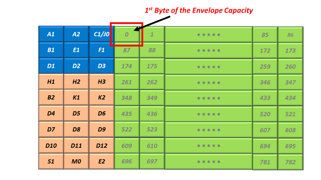
Figure 2, Illustration of the Very First Byte within the Envelope Capacity
Figure 2 also shows that Byte 1 (the 2nd byte within the Envelope Capacity) is located just to the right of Byte 1, and so on.
I show the Byte Numbering scheme for the Envelope Capacity below in Figure 3.
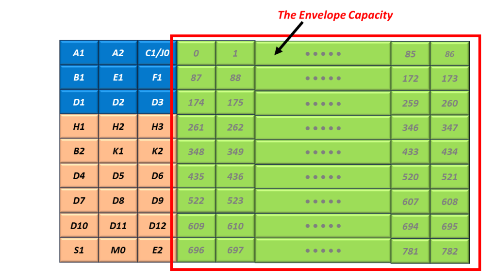
Figure 3, Byte-Numbering Scheme within the Envelope Capacity, within an STS-1 Frame (from Bytes 0 to Byte 782).
So, Where is the SPE?
The SPE is located in the exact same space as the Envelope Capacity. However, its Byte Numbering Scheme is different.
I show a drawing of the SPE below in Figure 4.
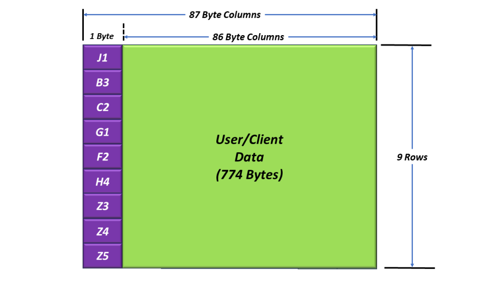
Figure 4, The SPE (Synchronous Payload Envelope)
Figure 4 shows the SPE (e.g., the Payload or User Data) along with the Nine Path Overhead (POH) bytes located in the left-most column (of the SPE). This figure also shows that the STS-1 SPE is a 9 Row x 87 Byte Column Structure (the same size as the Envelope Capacity).
I discuss the role/function of the Path Overhead (or POH) bytes in another blog post.
Figure 4 also shows that the very first byte of the SPE is the J1 byte (located in the upper left-hand corner of the SPE).
What is the Byte-Numbering Scheme of the SPE within an STS-1 Frame
So, What is the Byte-Numbering Scheme of the SPE within an STS-1 Frame
The Byte-Numbering scheme differs for the STS-1 SPE from what we showed for the Envelope Capacity.
In the case of the Envelope Capacity, Byte 0 is located just to the right of the C1/J0 byte (within the SOH), as I stated earlier. Further, Byte 0 (within the Envelope Capacity is always in that same location (just East of the C1/J0 byte).
In the case of the SPE, Byte 0 (e.g., the J1 byte) is located wherever the Pointer Bytes (H1 and H2) say that it is. The H1 and H2 bytes permit the SONET Receiver to locate the SPE within the STS-1 frame.
The main difference between the SPE and the Envelope Capacity is that the location of the Envelope Capacity is fixed (Byte 0 is always located just East of the C1/J0 Byte).
In the case of the SPE, Byte 0 (the J1 byte within the POH) can “float” anywhere within the Envelope Capacity.
The Envelope Capacity and the SPE have the same roles and are of the same size (e.g., 783 bytes). However, the location of the Envelope Capacity is fixed and aligned with the SOH and LOH bytes within the STS-1 Frame.
The location of the SPE is not fixed (with respect to the SOH and LOH bytes) and can float. This means that the SPE can begin within any of the 783 bytes within the Envelope Capacity.
I discuss the roles of the H1, H2, and H3 bytes and the location of the SPE (within the Envelope Capacity) in another blog post.
However, in Figures 5, 6, 7, and 8, I show a couple of possible locations of the SPE (within the Envelope Capacity).
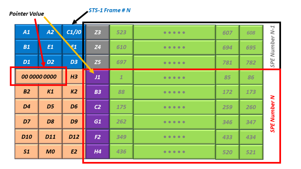
Figure 5, Illustration of the SPE, located at Byte 0 (just to the right of the H3 byte) – STS-1 Frame N.
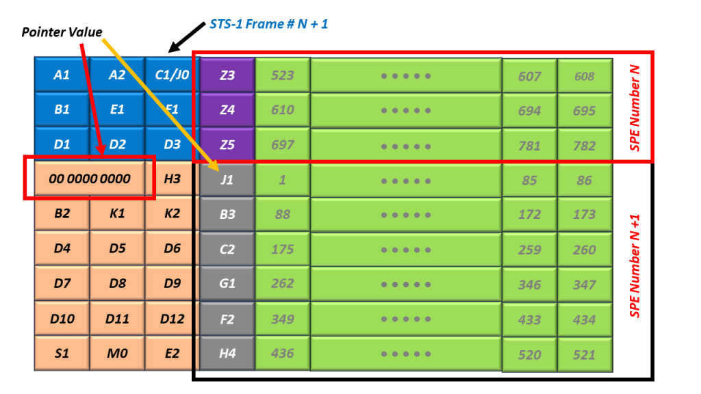
Figure 6, Illustration of the SPE (again located at Byte 0) – STS-1 Frame N+1.
In Figures 5 and 6, I also show that the pointer’s value (within the H1 and H2 bytes) is 0. In this case, the SPE begins at Byte 0 (the Byte just to the right of the H3 byte).
Please note that the SPE will often straddle across two consecutive STS-1 frames. Figure 5 shows the location of the SPE within STS-1 Frame N. Further, Figure 6 shows the location of the same SPE within the next frame (STS-1 Frame N+1).

Figure 7, Illustration of the SPE, located at Byte 522 (just to the right of the C1/J0 byte).
In Figure 7, I show that the value of the H1 and H2 bytes are 522 (0x020A). In this case, the SPE happens to be (accidentally) aligned with the SOH and LOF of the STS-1 Frame and located just to the right of the C1/J0 byte.
What Do the Pointer Values (within the H1 and H2 Bytes) Mean?
Finally, I show the Byte Numbering Scheme for SPEs in Figure 8.

Figure 8, What the Values of the H1 and H2 Bytes Mean – for the location of the J1 Byte within the SPE.
In other words, Figure 8 presents the relationship between the value of the Pointers (within the H1 and H2 byte) and the location of the J1 Byte (within the SPE) within the STS-1 Frame.
Figure 8 shows that a Pointer Value of 0 corresponds with the STS-1 SPE starting at the byte, just to the right of the H3 Byte. I show an example of an SPE at this location in Figures 5 and 6.
This same figure also shows that a Pointer Value of 522 corresponds with the STS-1 SPE starting at the byte, just to the right of the C1/J0 byte. I show an example of an SPE at this location in Figure 7.
Why Don’t We Fix the Location of the SPE within the STS-1 Frame?
One important difference that the SPE has (from that of the Envelope Capacity) is that the location of the SPE can move from time to time. We refer to events (in which the SPE changes its location within the STS-1 Frame) as Pointer Adjustment events.
Whenever these Pointer Adjustment events occur, the values within the Pointer Bytes (e.g., the H1 and H2 bytes) will change. The SONET Network uses pointer adjustment to accommodate timing differences throughout the network.
I will discuss the H1, H2, H3 bytes, and Pointer Adjustments in another blog post.