This blog post presents a video that discusses the APS features within some fo the Atomic Functions that we discussed in Lesson 11.
Lesson 12 – Video 13 – Detailed Implementation of APS within the Atomic Functions – Video 2
This blog post continues our discussion of the APS features within various Atomic Functions. In this case, we will present how to implement Automatic Protection Switching in great detail. In particular, we will describe the following:
APS Features within the ODUT/ODU_A_So and ODUT/ODU_A_Sk functions (ODUT/TCM Layer – SNC/S Monitoring)
How do we implement the APS features within these Atomic Functions to support TCM Layer i SNC/S Monitoring and Protection-Switching?
How do we implement a complete System-Level design (using these atomic functions along with the ODUT_TT_So and ODUT_TT_Sk Atomic Functions)?
NOTE: We discussed these atomic functions in Lesson 11. However, we did not discuss the APS features (within those functions) then.
More specifically, we discuss how our system should implement APS and the APS Communication Protocol whenever the upstream ODUT_TT_Sk Atomic Function declares either a Service-Affecting or the TCMi-dDEG defect.
This blog post presents a video that concludes our discussion of APS Commands via the APS/PCC Communications Protocol
Lesson 12 – Video 11 – Detailed Discussion of APS Commands – Video 4
This blog post completes our discussion of APS Commands and the APS/PCC Communications Protocol. This video serves as Video 4 in this discussion. This blog post briefly discusses the SD, Manual Switch, Wait-to-Restore (WTR), Reverse-Request (RR), and Do-Not-Revert (DNR) APS Commands.
Additionally, this video defines and discusses the 1 Phase APS Communication, 2 Phase APS Communication and 3 Phase APS Communication Procedures.
Finally, this video will define APS Recovery Time. This video will also present the ITU-T G.873.1 APS Recovery Time Requirements.
More specifically, this video will cover the following topics:
Detailed Topics Discussed
APS Commands (Continued)
SD_W (Signal Degrade in the Working Transport Entity)
SD_P (Signal Degrade in the Protection Transport Entity)
This blog post contains a video that continues the discussion of the APS Commands. This video serves as Video 3 of this series of APS Command videos.
Lesson 12 – Video 10 – Detailed Discussion of APS Commands – Video 3
This blog post continues our discussion of APS Commands and the APS/PCC Communication Protocol. This video serves as Video 3 in this discussion. This blog post discusses completing the Force Switch Commands and the SF (Signal Fail) Commands using the APS/PCC Communication Protocol.
In particular, this video will discuss the following topics:
Executing the Force Switch – Normal Traffic Signal n to Protection (for the 1:N Protection Architecture) – Continued from Video 9
Implementing the Force Switch – NULL Test Signal to Protection Command – another way to resume Normal Operation.
Signal Fail APS Commands
Executing the Signal Fail – Working Transport Entity (SF_W) Command (for the 1+1 Protection Architecture)
How does a given Network Element invoke the SF_W Command?
The Protection Group’s operation during SF_W Command execution.
How do we recover from this Command (for a Reverting System)?
Use of the WTR (Wait-to-Restore) Command
Executing the Signal Fail – Protection Transport Entity (SF_P) Command (for the 1+1 Protection Architecture)
How does a given Network Element invoke the SF_P Command?
The Protection Group’s operation during SF_P Command execution.
How do we recover from this Command?
Executing the Signal Fail – Working Transport Entity (SF_W) Command (for the 1:N Protection Architecture)
How does a given Network Element invoke the SF_W Command?
The Protection Group’s operation during SF_W Command execution.
How do we recover from this Command (for a Reverting System)?
Use of the WTR (Wait-to-Restore) Command.
Executing the Signal Fail – Protection Transport Entity (SF_P) Command (for the 1:N Protection Architecture)
How does a given Network Element invoke the SF_P Command?
The Protection Group’s operation during the SF_P Command execution.
This blog post presents a video that continues our discussion of APS Commands via the APS/PCC Communication Protocol. This video serves as Part 2 of this discussion.
Lesson 12 – Video 9 – Detailed Discussion of APS Commands – Video 2
This blog post continues our discussion of APS Commands and the APS/PCC Communication Protocol. This video serves as Video 2 in this discussion. This blog discussed implementing the LoP (Lock Out of Protection) and Force Switch Commands using the APS/PCC Communication Protocol.
In particular, this video will discuss the following topics:
Executing the LoP (Lock Out of Protection Command) – for both the 1+1 and 1:N Protection Architectures
What does the LoP Command do to the Protection Group?
How do we Implement this Command?
How do we Terminate this Command (to resume Normal Operation)
Executing the Force Switch – Normal Traffic Signal to Protection (for the 1+1 Protection Architecture)
How does this command’s execution affect the Protection Group’s operation?
How do we Implement this Command?
Implementing the Force Switch – NULL Test Signal to Protection Command – to resume Normal Operation.
Executing the Force Switch – Normal Traffic Signal n to Protection (for the 1:N Protection Architecture)
How does this command’s execution affect the Protection Group’s operation?
How do we Implement this Command?
Implementing the Force Switch – Extra Traffic Signal to Protection Command – to resume Normal Operation.
To Learn More About the LoP (Lock Out of Protection) and Force Switch Commands, Check Out the Video Below.
This blog post presents a video that shows how to implement APS (Automati Protection Switching) both with and without using an APS Communication Protocol.
Lesson 12 – Video 8 – Detailed Discussion of APS without and with the APS Communication Protocol – Video 1
This blog post describes how we can implement APS (Automatic Protection Switching) without using an APS Communication Protocol. Afterward, this blog introduces how to implement APS using the APS Communication Protocol. This video serves as the first of several videos on this topic.
In particular, this video will discuss the following topics:
Executing APS without using the APS Communication Protocol
Under what conditions can we implement APS without using an APS Communication Protocol?
Why can we implement APS (without an APS protocol) in this case?
When not supporting an APS Communication Protocol, the Architecture/Design of the Protection-Switching Controllers.
How to implement Automatic Protection Switching – without implementing an APS Communication Protocol.
Executing APS with an APS Communication Protocol
Under what conditions must we implement APS with an APS Communication Protocol?
Why do we need to use an APS Communication Protocol for these cases?
How to implement Automatic Protection Switching – while using an APS Communication Protocol
Introduction to the APS/PCC Field for OTN/Linear Protection Switching Applications (per ITU-T G.873.1).
The Architecture/Design of the Protection-Switching Controllers – 1+1 Protection Architecture
The Architecture/Design of the Protection Switching Controllers – 1:N Protection Architecture
The NR (No Request) Command
To Learn How to Implement APS, with and without an APS Communication Protocol, Check Out the Video Below.
This blog post briefly defines and describes the Nibble and Byte fields of the APS/PCC field, for Linear-Protection-Switching and OTN Applications.
Introduction to the APS/PCC Field
This blog post aims to define and describe the byte format of the APS/PCC field within the ODU Overhead whenever we support Linear Protection Switching applications within the OTN. ITU-T G.873.1 specifies the byte/nibble format of the APS/PCC field that we use within the OTN for Linear Protection Switching.
Whenever the System Designer needs to support the following:
Linear Protection Switching within the Optical Transport Network (defined within ITU-T G.709)
An APS Communication Protocol (because the user is either using the 1:N Protection Architecture or Bidirectional Switching
Then the user will need to use the APS/PCC (Automatic Protection Switching/Protection Control Communications) channel (and field) to support the APS protocol.
The APS/PCC field resides within the ODU Overhead, as I show below in Figure 1.
Figure 1, Location of the APS/PCC Field within the ODU Overhead of an OTU Frame.
Figure 1 shows that the APS/PCC field resides within the fourth row and the fifth through eighth-byte position within an OTU frame. The length of the APS/PCC field is four bytes wide.
Whenever we are designing OTN networks to also support protection switching (and using the APS Communications Protocol) in the process, then we will use the APS/PCC field to transport APS Messages from one Network Element to another.
Byte/Nibble Format of the APS/PCC Field
I show the Byte/Nibble format of the APS/PCC field below in Figure 2.
Figure 2, Byte/Nibble format of the APS/PCC Field
Figure 2 shows that the APS/PCC field consists of the following Nibbles and Byte-fields:
Request/State Nibble (Bits 1-4)
The purpose of this Nibble-field is to either:
Transmit Protection-Switching commands or requests to the remote terminal of the Protection-Group, or
Transmit information about Defect Conditions or States.
Table 1 presents a list of values (within the Request/State Nibble field) and their corresponding Meaning.
Table 1, Standard Values within the Request/State Nibble field and their Corresponding Meaning.
So, for example, if a given Protection Switching terminal needs to transmit the SF Command, it would set the Request/State Nibble (within its outbound APS Message) to [1, 1, 0, 0], as I show in Table 1.
Protection Type Nibble (Bits 5 – 8)
The Protection Type Nibble field occupies the second set of four bits of the APS/PCC field.
The purpose of this nibble-field is to communicate (to the remote end of the Protection Group) many of the governing parameters of our Protection-Switching scheme.
The following table presents a list of the bit-fields within the Protection-Type Nibble and their meaning/description.
Table 2, A List of the Bit-Fields, within the Protection-Type Nibble and their Meaning/Description
Bit A – APS Channel
This bit-field indicates if the Protection Group is either supporting an APS Communication Protocol or not, as I describe below.
0 = No APS Channel (Not using the APS Communication Protocol)
1 = APS Channel (We are using the APS Communication Protocol)
Bit B – Bridge (Permanent)
This bit-field indicates if the Protection Group supports the 1+1 or 1:N Protection Architecture, as I show below.
This bit-field indicates if the Protection Group supports the Revertive or Non-Revertive Operation, as I show below.
0 = Non-Revertive Operation
1 = Revertive Operation
Requested Signal Byte – APS/PCC Field – Byte 2
The Requested Signal byte-field identifies the signal that the Near-End (e.g., the Requesting Terminal) requests to be carried over to the Protection Transport Entity.
Ultimately, we a request at the Far-End Terminal to place the Requested Signal on the Protection Transport Entity, following this Protection Command.
For the 1+1 Protection Architecture
For the 1+1 Protection Architecture, the Protection-Switching Terminal should set this byte-field to “0x01” (for most APS Commands) to denote Normal Traffic Signal # 1. Normal Traffic Signal # 1 is typically the ONLY Normal Traffic Signal in a given direction for a 1+1 Protection Switching Architecture.
For the 1:N Protection Architecture
If the Requesting Terminal wishes to command the remote end to bridge the NULL Test Signal to the Protection Transport entity, it should set this byte-field to 0x00 when issuing an APS command.
Likewise, suppose the Requesting Terminal wishes to command the remote end to bridge the Extra Traffic Signal to the Protection Transport entity. In that case, it should set this byte-field to 0xFF when issuing an APS command.
Finally, suppose the Requesting Terminal wishes to command the remote end to bridge a Normal Traffic Signal to the Protection Transport entity. During a Protection Switching event, it should set this byte-field to the appropriate number (corresponding with the defective Normal Traffic Signal). Valid Numbers for the Requested Byte value range from 0x01 to 0xFE, depending upon which Normal Traffic signal requires Protection-Switching.
Table 2 lists the appropriate Requested Signal Values for the 1:N Protection Architecture.
Table 2, List of Appropriate Requested Signal Values for the 1:N Protection Architecture
Bridged Signal Byte – APS/PCC Field – Byte 3
For this field, the REQUESTING terminal will set this byte-field to the value that identifies which signal this terminal is currently bridging to the Protection Transport entity.
For the 1+1 Protection Architecture
When using the 1+1 Protection Architecture, the Protection-Switching Terminal should set this byte-field to “0x01” (for most APS Commands) to denote Normal Traffic Signal # 1. Normal Traffic Signal # 1 is typically the ONLY Normal Traffic Signal in a given direction for a 1+1 Protection Switching Architecture.
For the 1:N Protection Architecture
If the Requesting Terminal is bridging the NULL Test Signal to the Protection Transport entity, it must set this byte-field to 0x00 when issuing an APS command. The Requesting Terminal tells the remote terminal that it is bridging the NULL Test Signal to the Protection Transport entity.
Likewise, if the Requesting Terminal is bridging the Extra Traffic Signal to the Protection Transport entity, it must set this byte-field to 0xFF when issuing an APS command.
Finally, suppose the Requesting Terminal is currently implementing Protection Switching and is bridging one of the Normal Traffic Signals to the Protection Transport entity. In that case, it must identify that Normal Traffic Signal by setting this byte-field to the appropriate number (corresponding with the defective Normal Traffic Signal). Valid Numbers for the Requested Byte value range from 0x01 to 0xFE, depending upon which Normal Traffic signal requires Protection-Switching.
Table 3 presents a list of the appropriate Bridged Signal Values for the 1:N Protection Architecture.
Table 3, List of Appropriate Bridged Signal Values for the 1:N Protection Architecture
Reserved Byte – Byte 4
This byte-field is reserved for future use/standardization.
Clueless About OTN? We Can Help!! Click Below to Learn More!!
Example of Using the APS/PCC Field for the 1+1 Protection Architecture
Let’s suppose we use the 1+1 Protection Architecture within our Protection Scheme. Further, let’s assume that one of the Network Elements declares the SF_W (Signal Fail within the Working Transport Entity) condition, as shown below in Figure 3.
Figure 3, Tail-End Circuit at NE Z declares the SF_W Condition.
NE Z Sends the SF_W APS Message to NE A
In this case, NE Z (the Network Element declaring the SF_W Condition) will need to send the SF_W APS Command to the remote terminal. I show this APS Command below in Figure 4.
Figure 4, NE Z sending the SF_W APS Command to NE Z.
Please note that (within this APS Command) NE Z is setting the Request Command to [1, 1, 0, 0] to denote that it is transmitting the SF Command.
Further, NE Z is also setting the Protection Type Nibble to information NE A, which is operating with the following Protection-Switching characteristics:
A = 1: We are using an APS Communication Protocol
B = 0: We are using a Permanent Bridge (for a 1+1 Protection Architecture)
D = 1: We are supporting Bidirectional Switching, and
R = 1: We are supporting Revertive Switching
Next, NE Z is setting the Requested Byte to “0x01”. This setting denotes two things:
First, we are declaring the SF condition within the Working Transport Entity. If we set the Requested Byte to “0x00”, this would denote that we are declaring the SF condition with the Protection Transport entity.
Second, we are requesting that the remote terminal (NE A, within Figure 4) should bridge the Normal Traffic Signal (Signal # 0x01) to the Protection Transport entity. (NOTE: Because this is the 1+1 Protection Architecture, we are already permanently bridging the Normal Traffic Signal (0x01) to the Protection Transport entity.
Finally, NE Z is setting the Bridged Byte to “0x01”. This setting denotes that we are already bridging the Normal Traffic Signal (0x01) to the Protection Transport Entity. The Permanent Bridge is inherent to the 1+1 Protection Architecture.
Subsequent APS Commands
NE A and NE Z will exchange more APS Commands to deal with this instance of the SF condition. I’m only showing the initial request from NE Z to NE A.
Example of Using the APS/PCC Field for the 1:N Protection Architecture
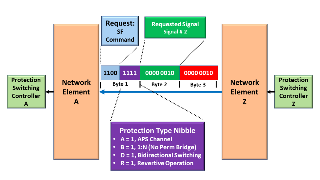
Let’s suppose we are using the 1:N Protection Architecture within our Protection Scheme. Further, let’s assume that one of the Network Elements declares the SF_W Condition with Working Transport Entity # 2, as I show below in Figure 5.
Figure 5, Tail-End Circuit at NE Z declares the SF_W Condition for Working Transport Entity # 2.
NE Z Send the SF (within Normal Traffic Signal # 2) Message to NE A
In this case, NE Z (the Network Element declaring the SF_W Condition) will need to send the SF_W APS Command to the remote terminal. I show this APS Command below in Figure 6.
Figure 6, NE Z sending the SF_W APS Command to NE Z.
Please note (again) that (within this APS Command) NE Z is setting the Request Command to [1, 1, 0, 0] to denote that it is transmitting the SF Command.
Further, NE Z is also setting the Protection Type Nibble to information NE A, which is operating with the following Protection-Switching characteristics:
A = 1: We are using an APS Communication Protocol
B = 1: We are using a Non-Permanent Bridge (for a 1:N Protection Architecture)
D = 1: We are supporting Bidirectional Switching, and
R = 1: We are supporting Revertive Switching
Next, NE Z is setting the Requested Byte to “0x02”. This setting denotes two things:
First, we are declaring the SF condition within the Working Transport Entity. If we set the Requested Byte to “0x00”, this would denote that we are declaring the SF condition with the Protection Transport entity.
Second, we are requesting that the remote terminal (NE A, within Figure 5) should bridge the Normal Traffic Signal # 2 (Signal # 0x02) to the Protection Transport entity. We are declaring the defect with Working Transport Entity # 2. We need to alert the remote terminal that we need to bypass this signal path.
Finally, NE Z is setting the Bridged Byte to “0x02”. This setting denotes that we are already bridging the Normal Traffic Signal # 2 (0x02) to the Protection Transport Entity.
Subsequent APS Commands
NE A and NE Z will exchange more APS Commands to deal with this instance of the SF condition. I’m only showing the initial request from NE Z to NE A.
Has Inflation got You Down? Our Price Discounts Can Help You Fight Inflation and Help You Become an Expert in OTN!! Click on the Banner Below for More Details!!
Click on the Image Below to see more Protection-Switching related content on this Blog:
This blog post presents a video that describes (in detail) SNC/S (Subnetwork Circuit Protection – Sublayer) Monitoring for Protection Switching.
Lesson 12 – Video 7 – Detailed Discussion of SNC/S (Subnetwork Circuit – Sublayer) Monitoring for Protection Switching
This blog post contains a video that presents a detailed discussion of SNC/S (Subnetwork Circuit – Sublayer) Monitoring for Protection Switching purposes at the ODU Layer.
In particular, this video will discuss the following topics:
A Detailed Review of SNC/S (Subnetwork Circuit Protection/Sublayer) Monitoring.
This video shows example locations/conditions of where we would use SNC/S Monitoring and why we would use this form of monitoring.
This video also highlights similarities of SNC/S with SNC/I Monitoring.
It also shows the differences between SNC/S and SNC/Ne or SNC/Ns monitoring.
Finally, this video reviews a Multi-Administrative Domain Network (and Tandem Connection Monitoring) and describes how SNC/S works within a given “Protect Domain.”
This blog post presents a video that describes (in detail) SNC/N (Subnetwork Protection – Non-Intrusive) Monitoring for Protection Switching.
Lesson 12 – Video 6 – Detailed Discussion of SNC/N (Subnetwork Circuit – Non-Intrusive) Monitoring for Protection Switching
This blog post contains a video that presents a detailed discussion of SNC/N (Subnetwork Circuit – Non-Intrusive Monitoring, for Protection-Switching purposes, at the ODU Layer.
In particular, this video will discuss the following topics:
A Detailed Review of SNC/Ne (Subnetwork Circuit Protection/Non-Intrusive End-to-End) Monitoring, and
A Detailed Review of SNC/Ns (Subnetwork Circuit Protection/Non-Intrusive Sublayer) Monitoring.
This video shows example locations/conditions of where we would use SNC/Ne or SNC/Ns Monitoring and why we would use this form of monitoring.
This video also highlights the similarities and differences between SNC/Ne and SNC/Ns Monitoring.
This blog post presents a video that describes (in detail) CL-SNCG/I (Compound Links – Subnetwork Circuit Group – Inherent) Monitoring for Protection Switching.
Lesson 12 – Video 5 – Detailed Discussion of CL-SNCG/I (Compound Links – Subnetwork Circuit Group – Inherent) Monitoring for Protection Switching
This blog post contains a video that presents a detailed discussion of CL-SNCG/I Monitoring ], for Protection Switching purposes, at the ODU layer.
In particular, this video will discuss the following topics:
A Quick Review of the SNC/I Monitoring at the ODU Layer
A Single ODUj Tributary is the Normal Traffic Signal
How CI_SSF and CI_SSD initiate Protection Switching
How to perform CL-SNCG/I Monitoring at the ODU Layer
What Circuitry (Atomic Functions) that we should use
What defects to monitor
Which is the Normal Traffic Signal when doing CL-SNCG/I Monitoring at the ODU Layer?
What happens when we declare an ODUk Server-Layer service-affecting defects (such as dAIS, dOCI, dLCK, dTIM)?
What happens when we declare the PM-dDEG (ODU-Layer Signal Degrade) defect?
How does protection-switching work?
How does CL-SNCG/I Monitoring (for Protection-Switching) differ from SNC/I Monitoring for Protection-Switching?
PI-TSF/PI-TSD versus CI_SSF[n]/CI_SSD[n]
Multiple ODUj Tributary Signals are the Normal Traffic Signal
dPLM, dLOOMFI, dMSIM[n], and dLOFLOM[n] do not cause Protection-Switching when CL-SNCG/I Monitoring.