Lesson 5/PT = 0x20/16 ODU1 – Mapping/Multiplexing 16 ODU1 Tributary Signals into an ODU3 Server Signal

This blog post presents a video that shows how to map/multiplexing as many as 16 ODU1 tributary signals into an ODU3 server signal, using the PT = 0x20 approach.

Mapping/Multiplexing 16 ODU1 Tributary Signals into an ODU3 Server Signal (PT = 0x20)

This blog post includes a video that shows how we map and multiplex as many as 16 ODU1 Tributary Signals into an ODU3 Server Signal, using the PT = 0x20 Approach.

In this video, we discuss the following:

  • Using the AMP (Asynchronous Mapping Procedure) to map the ODU1 tributary signals into their respective ODTU13 signal/frames.
  • How to combine these ODTU13 signals and map them into an ODU3 payload.
  • Transporting these AMP Justification parameters from the Source PTE (where we map/multiplex these ODU1 tributary signals into the ODU3 server signal) to the Sink PTE (where we de-multiplex and de-map out the ODU1 tributary signals).
  • Multiplex Structure Identifiers within this type of ODU3 signal.

You can view this video below.

Continue reading “Lesson 5/PT = 0x20/16 ODU1 – Mapping/Multiplexing 16 ODU1 Tributary Signals into an ODU3 Server Signal”

Lesson 5/PT = 0x20/4 ODU2 – Mapping/Multiplexing 4 ODU2 Tributary Signals into an ODU3 Server Signal

This blog post presents a video on how to map/multiplex as many as 4 ODU2 tributary signals into an ODU3 server signal, using the PT = 0x20 approach.

Mapping/Multiplexing 4 ODU2 Tributary Signals into an ODU3 Server Signal using the PT = 0x20 Scheme.

This blog post includes a video that shows how we map and multiplex as many as 4 ODU2 Tributary Signals into an ODU3 Server Signal, using the PT = 0x20 Scheme.

In this video, we discuss the following:

  • Sub-dividing an ODU2 tributary signal into its 2.5 Gbps time-slots.
  • Use the AMP (Asynchronous Mapping Procedure) to map each ODU2 tributary signal into an ODTU23 signal/frame.
  • How to combine these ODTU23 signals and map them into an ODU3 payload.
  • Transporting the AMP Justification Parameters from the Source PTE (where we map/multiplex the ODU2 tributary signals into the ODU3 server signal) to the Sink PTE (where we de-multiplex and de-map out the ODU2 tributary signals).
  • The Multiplex Structure Identifiers within this type of ODU3 signal.

You can view this video below.

Continue reading “Lesson 5/PT = 0x20/4 ODU2 – Mapping/Multiplexing 4 ODU2 Tributary Signals into an ODU3 Server Signal”

Lesson 5/PT = 0x20, Mapping/Multiplexing 4 ODU1 Tributary Signals into an ODU2 Server Signal.

This blog post presents a video on how to map/multiplex as many as four ODU1 tributary signals into an ODU2 server signal, using the PT = 0x20 approach.

Mapping/Multiplexing 4 ODU1 Tributary Signals into an ODU2 Server Signal using the PT = 0x20 Approach

This blog post includes a video that shows how we map and multiplex as many as 4 ODU1 Tributary Signals into an ODU2 Server Signal, using the PT = 0x20 Approach.

In this video, we discuss the following:

  • Using the AMP (Asynchronous Mapping Procedure) to map the ODU1 tributary signals into the ODTU12 signals/frames.
  • How to combine the ODTU12 signals and then map them into an ODU2 payload.
  • Transporting the AMP Justification parameters from the Source PTE (where we map/multiplex the ODU1 signals into the ODU2 Server signal) to the Sink PTE (where we de-multiplex and de-map out the ODU1 tributary signals).
  • Multiplex Structure Identifiers within this type of ODU2 signal.

You can view this video below.

Continue reading “Lesson 5/PT = 0x20, Mapping/Multiplexing 4 ODU1 Tributary Signals into an ODU2 Server Signal.”

OTN – Lesson 10 – Video 1M – Entire Source Direction Path – All Atomic Functions (ODU Multiplexed Applications)

This post presents the 1st of the 6 Videos that covers training on the Peformance Monitoring of the ODUk Layer (for Multiplexed Applications). This post focuses on the Source Direction ODU-Layer Atomic Functions.

OTN – Lesson 10 – Video 1 – The Entire Source Direction Path – All Atomic Functions (ODU Multiplexed Applications)

Check Out the Video Below

Click HERE to Go to Video 2 – The OTUk/ODUk_A_Sk and ODUk_TT_Sk Atomic Functions
Click HERE to return to the Main Lesson 10 Page – Multiplexed Applications

What We Cover in this Video

Video 1 (of the Multiplexed ODu4 System Videos) covers the following topics.

  • A brief review of Multiplexed Applications:
    • The PT = 0x20 Approach, and
    • The PT = 0x21 Approach
  • A brief review of the ITU-T G.798 Atomic Function’s support of the Multiplexed Applications
    • The ODUkP/ODU[i]j_A_So/Sk Functions (for PT = 0x20 Applications), and
    • The ODUkP/ODUj-21_A_So/Sk Functions (for PT = 0x21 Applications)
  • Our Application Example: 80 Channels of 1000BASEX -> ODU0 -> ODU4
  • ODU0P/CBR_ETC1000X-A_So (1Gbps Ethernet Adaptation Source Function)
  • Main Purpose: To take a 1000BASE-X (1Gbps Ethernet signal) and map this signal into an ODU0 signal using the GMP-TTT Mapping Procedure.
    • Generates a Default PMOH within the outbound ODU0 signal.
    • Sends the ODU0 signal towards the downstream ODU0_TT_So function for further processing
    • On-Board Clock Generator
      • Synthesizes a 1.244160 GHz Clock signal (e.g., the ODU0 bit-rates per ITU-T G.709) along with the AI_CK, AI_FS, and AI_MFS output signals to create an ODU0 signal.
    • ODU0 Overhead Settings
      • PT (Payload Type) within the PSI Message – set to 0x07 for 1000BASE-X mapped into an ODU0.
      • CI_SSF -> CSF bit-field within the outbound PSI Message (of OPU0 Frame)
  • ODU0_TT_So Function
  • Main Purpose: To compute a Real (and Correct) PMOH and insert data into its ODU0 data-stream.
    • The role of this function is very similar to what we described back in the discussion of the ODUk_TT_So function (in the Non-Multiplexed Portion of Lesson 10).
  • ODUkP/ODUj-21_A_So Function (ODUk to ODUj Multiplex Source Function)
  • Main Purpose: In this example, the ODUkP/ODUj-21_A_So function will map and multiplex 80 ODU0 signals into an OPU4/ODU4 server signal.
    • Convert each ODUj tributary signal into an Extended ODUj signal by attaching the FAS and MFAS fields to each ODUj frame.
    • APS Support
      • Within the ODUj Tributary Signal itself, and
      • Within the ODUk Server Signal
    • Can configure each ODUj tributary to operate in the Locked Mode (e.g., it overwrites the ODUj tributary signal with the ODUj-LCK Maintenance signal and maps/multiplexes that signal into the ODUk server signal.
    • Setting the PT byte (within the outbound ODUk server signal to 0x21).
    • Quick Review of the MSI bytes (within each outbound PSI Message).
    • The OMFI Byte-field (for ODU4 Multiplexed Applications ONLY).
    • We set the PMOH within the ODUk Server Signal to the Default Values. Route this signal to the downstream ODUk_TT_So Function.
  • ODUk_TT_So Function
  • Main Purpose: To compute a Real (and Correct) PMOH and insert data into its ODU4 data stream.
    • The role of this function is the same as what we described back in the discussion of the ODUk_TT_So function (in the Non-Multiplexed Portion of Lesson 10).
  • OTUk/ODUk_A_So Function
  • Main Purpose: To map an ODU4 client signal into the OTU4 Server signal.
    • The role of this function is the same as what we described back in the discussion of the ODUk_TT_So function (in the Non-Multiplexed Portion of Lesson 10).

In Figure 1, I highlight the Atomic Functions discussed in Video 1.

ODU4/OTU4 Multiplexed System with the Source Direction Atomic Functions Highlighted

Figure 1, Illustration of the ODU4/OTU4 System, with the Atomic Functions that we discuss in Video 2 highlighted

You Can Also Check Out the Video Below:

Click HERE to Go to Video 2 – The OTUk/ODUk_A_Sk and ODUk_TT_Sk Atomic Functions

Click HERE to return to the Main Lesson 10 Page – Multiplexed Applications

Resources, Corrections, and Additional Information about this Post

Resources Page - Lesson 10 - ODU Layer Defect Handling and Performance Monitoring Requirements

Resources – OTN Lesson 10

Resources - OTN Lesson 10 - ODU Layer Defect Handling and Performance Monitoring Requirements This page contains links to various ...
The Forum

The Forum Page

The Best Darn OTN Training ... Period - Forum This page serves as a place-holder for the Forum. The Forum ...
Mistakes and Corrections to OTN Lesson 10 - ODU Layer Defects and Performance Monitoring Requirements

OTN – Lesson 10 – Mistakes/Corrections

OTN Lesson 10 - ODU Layer Defects and Performance Monitoring Requirements - Mistakes/Corrections This page identifies any mistakes and corrections ...

Lesson 5 – PT = 0x20 Approach

This blog post provides information and Video Training on the PT = 0x20 Approach for Mapping/Multiplexing Lower-Speed ODUj Tributary Signals into an ODUk Server Signal.

Lesson 5 – PT = 0x20 Approach to Mapping/Multiplexing Lower-Speed ODUj Tributary Signals into an ODUk Server Signal.

This portion of Lesson 5 presents information, along with a Training Video on how we Map and Multiplex Lower-Speed ODUj Tributary Signals into a Higher-Speed ODUk Server Signal using the PT = 0x20 Approach.

This Lesson includes four (4) videos discussing mapping/multiplexing lower-speed ODUj Tributary Signals into an OPUk/ODUk Server Signal using the PT = 0x20 scheme.

Introduction to the PT = 0x20 Scheme and Mapping/Multiplexing up to 2 ODU0 Tributary Signals into an ODU1 Server Signal

This video covers the following topics.

  • An overall discussion of the PT = 0x20 Scheme to Mapping and Multiplexing Lower-Tributary ODUj signals into an ODUk Server signal.
  • How do we use the PT =0x20 Approach to mapping/multiplexing 2 ODU0 signals into an ODU1 server signal? As this video discusses this particular mapping/multiplexing scheme, it will cover the following items in detail.
    • Using the AMP (Asynchronous Mapping Procedure) to map each ODU0 tributary signal into an ODTU01 frame/signal.
    • How do we combine each ODTU01 signal and map this data into the ODU1 payload?
    • Transporting these AMP Justification parameters from the Source PTE (where we map/multiplex these ODU0 tributary signals into the ODU1 server signal) and the Sink PTE (where we de-multiplex and de-map out the ODU0 tributary signals).
    • The Multiplexed Structure Identifier within this type of ODU1 server signal.

You can watch the Video Training that Introduces the PT = 0x20 Scheme and discusses Mapping/Multiplexing up to 2 ODU0 Tributary Signals into an ODU1 Server below.

Continue reading “Lesson 5 – PT = 0x20 Approach”

What is the Multiplex Structure Identifier

This post briefly defines the term Multiplex Structure Identifier (MSI) for OTN Applications.


What is the Multiplex Structure Identifier (MSI) within the PSI Message?

The purpose of this post is to define the term:  Multiplex Structure Identifier.

Introduction

Another post, we spoke about the PSI (Payload Structure Identifier) Message.

That post states a few things that are of interest to this post.

  • The PSI Message is a 256-byte Message that a given Source PTE will repeatedly transmit to the Sink PTE.
  • The Source PTE will repeatedly transmit this PSI Message via the PSI byte (within each ODUk/OPUk frame).
  • The purpose of this PSI Message is to permit the Source PTE to inform the Sink PTE of the type of traffic that this particular ODUk/OPUk server signal is transporting.
  • The first byte (Byte 0 – within the PSI Message) will be the PT (or Payload Type) byte.
  • This means that there are still 255 other bytes that are available to transport information within each PSI Message.
    • The PSI post also states two different types of PSI Messages.
      • The Non-Multiplexed Traffic Type of PSI Message, and
      • The Multiplexed Traffic Type of PSI Message.  

Suppose we’re discussing the MSI (Multiplex Structure Identifier), which involves OPU/ODU server signals transporting multiple lower-speed ODUj tributary signals.  In that case, we will deal with the Multiplexed Traffic Type of PSI Message.  

I show an illustration of the PSI byte-field (within an OPU frame) and a blow-up of the  Multiplexed-Traffic Type of PSI Message below in Figure 1.

OPU Frame with PSI Byte-Field Highlighted and a Breakout of the Multiplexed Structure PSI Message

Figure 1, Illustration of the PSI byte-field and a Multiplexed-Traffic Type of PSI Message

Please note that the PSI Message within Figure 1 does not contain a CSF (Client Signal Fail) bit-field.  Hence, you should be able to identify this PSI Message as being the Multiplexed Traffic type of PSI Message.  

A Multiplex Structure ODUk

If the Source PTE (transmitting an ODUk signal to the remote Sink PTE) has set the PT byte value (within each PSI Message) to 0x20 or 0x21, then this means that this ODUk signal is a Multiplex Structure ODUk signal.

If a given ODUk signal is a Multiplex Structure ODUk signal, then this means that it is transporting at least one lower-speed ODUj tributary signal within its payload (where k > j).

NOTE:  We will discuss PT = 0x22 and ODUCn signals in another post.

In this case, the Source PTE (or upstream circuitry) has mapped and multiplexed some number of lower-speed ODUj tributary signals into this particular higher-speed ODUk server signal.

For the OTN to work correctly, the Source PTE needs to send sufficient information to Sink PTE about the type of traffic/data that a given ODUk server signal carries.

Hence the purpose of the PSI Message.

The Sink PTE needs more information than the PT byte value

So if the Source PTE sets the PT Byte value (within each outbound PSI Message) to 0x20 or 0x21, then it is telling the remote Sink PTE that this ODUk signal is a Multiplex Structure signal that is transporting some number of Lower-Speed ODUj tributary signals.

However, the Sink PTE needs more information for it to be able to identify and handle this ODUk data stream accurately.

In particular, the Sink PTE needs to “know” how many and what type of lower-speed ODUj tributary signals this ODUk/OPUk server signal is transporting.  

We can think of the remaining bytes (within the PSI Message, following the PSI byte) as a passenger manifest for each of the Lower-Speed ODUj Tributary signals we are transporting within this OPUk/ODUk server.  And we can think of the ODUk server signal as the airplane (carrying many passengers).  

Depending upon the PT value and the type of OPUk/ODUk server signal that we are working with, the number of MSI bytes (within the PSI Messages for that particular server signal) will vary, as I show below.

For PT = 0x20

  • If we’re working with an OPU1/ODU1 server signal, the MSI will consist of 2 bytes.
  • If we’re working with an OPU2/ODU2 server signal, the MSI will consist of 4 bytes.
  • An OPU3/ODU3 server signal will use 16 bytes for its MSI.  
  • For PT = 0x20, each MSI byte (or entry) represents 2.5Gbps of bandwidth.  

For PT = 0x21

  • If we’re working with an OPU2/ODU2 server signal, the MSI will consist of 8 bytes.
  • An OPU3/ODU3 server signal will use 32 bytes for its MSI, and
  • An OPU4/ODU4 server signal will use 80 bytes for its MSI.  
  • For PT = 0x21, each MSI byte (or entry) represents 1.25Gbps of bandwidth.

Let’s Take a Look at an ODU4/OPU4 Signal

For example, if we are dealing with an ODU4 signal, and if the PT byte is set to 0x21, then the PSI Message (that this ODU4/OPU4 signal transports) would have the format that we show below in Figure 2.

Multiplex Structure Identifier for 80 ODU0 Signals within an OPU4 Signal

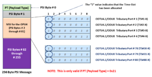
Figure 2, Illustration of the PSI Message for an ODU4/OPU4 that is transporting 80 ODU0 signals

Figure 2 shows the PSI Message that a Source PTE would carry (within an ODU4 signal) if that ODU4 signal were transporting 80 ODU0 signals (that it has mapped and multiplexed into this ODU4).

Please note that ODU4/OPU4 signals can transport other types of multiplexed traffic.  For example, it can carry any of the following types of multiplexed traffic.

  • 80 ODU0 signals.
  • 40 ODU1 signals
  • 10 ODU2 or ODU2e signals
  • 2 ODU3 signal
  • Some number of ODUflex signals (provided that the total bandwidth of all of these signals does not exceed 80 time-slots or the OPU4 payload carrying capacity of 104.35597533 Gbps).
  • Various combinations of each of the above signals (again, provided that the total bandwidth of all of these signals does not exceed 80 time-slots

Has Inflation got You Down? Our Price Discounts Can Help You Fight Inflation and Help You Become an Expert on OTN!! Click on the Banner Below to Learn More!!!

Discounts Available for a Short Time!!!

How to Read/Decipher these Multiplex Structure Identifier fields

Figure 2 shows that each PSI Message (starting at Byte 2) for an OPU4/ODU4 server signal has 80 consecutive bytes of data. 

These 80 bytes (of data) are the Multiplex Structure Identifier (MSI) for this OPU4/ODU4 serval signal.  In this case, each byte of data (within the MSI) represents a bandwidth of approximately 1.25Gbps, that we are transporting via the OPU4/ODU4 server signal.  

If we’re working with an OPU4/ODU4 server signal, then:

80 bytes x 1.25Gbps = 100Gbps.

And that makes sense because 100Gbps is the approximate bandwidth of an OPU4/ODU4 signal.  

The MSI will alert the Sink PTE of the type of Lower-Speed ODUj Tributary Signals we are transporting within this OPU4/ODU4 server signal. 

Is the Time-Slot Allocated?

The first bit-field (within each MSI byte) will indicate whether this 1.25Gbps time slot (within this OPU4/ODU4 server signal) has been allocated or not-allocated, as shown below in Figure 3.  

If this bit-field is set to “1”, then that particular time slot (or bandwidth) within the OPU4/ODU4 signal is allocated.  In this case, we are using this bandwidth to transport the individual ODUj tributary signal. 

Conversely, suppose this bit-field is set to “0”.  In that case, this particular time slot (or bandwidth) within the OPU4/ODU4 server signal is NOT allocated (or is not being used to transport a lower-speed ODUj tributary signal).  

NOTE:  In the PT = 0x21 post, we mention that each time-slot (for PT = 0x21 applications) represents approximately 1.25Gbps of bandwidth.

I have also included Figure 3, which will help you better understand these Multiplex Structure Identifier fields.

Mutliplex Structure Identifier Definition for OPU4 Applications

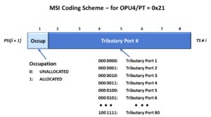
Figure 3, Multiplex Structure Identifier – Bit Definitions for ODU4/OPU4 Applications.  

The Port ID Number

The remaining 7-bits, within each MSI byte, are the Tributary Port Number (or Port ID Number.  

The Port ID Number identifies which lower-speed ODUj Tributary signal we are transporting within this OPU4/ODU4 server signal.  

Now, since each byte (within the MSI) represents a bandwidth of 1.25Gbps, then the number of times that we see a particular Port ID Number appearing within our 80 bytes of MSI indicates the bandwidth (and, in turn) the type ODUj Tributary signal that we are working with.

For example, if we only see that Port ID Number = 0x00 only appears once within this set of 80 bytes, then we know that this particular ODUj Tributary signal (that corresponds with Port ID Number = 0x00) has a bandwidth of:

1 byte x 1.25Gbps = 1.25Gbps

And it is most likely an ODU0 signal.  

In the case where we see that Port ID Number = 0x00 appears twice, within this set of 80 bytes, then we know that this particular ODUj Tributary signal has a bandwidth of:

2 bytes x 1.25Gbps = 2.50Gbps

And it is most likely an ODU1 signal.  

And so on.  

In Figure 2, I show that the MSI for this OPU4/ODU4 server signal consists of 80 bytes, in which the Port ID Numbers range from 0x00 to 0x4F (or 79 in decimal format). 

Each of the 80 MSI bytes contains a unique Port ID value.  In other words, no two MSI bytes contain the same Port ID value.  

This set of MSI bytes indicates that this OPU4/ODU4 server signal is transporting 80 ODU0 tributary signals or 80 sets of signals with a bandwidth of 1.25Gbps.  

Other Examples of Multiplex Structure Identifiers (Coming Soon to this Blog)

  • PT = 0x21 Applications
    • ODU2/OPU2 Server Applications
    • ODU3/OPU3 Server Applications
    • ODU4/OPU4 Server Applications
  • PT = 0x20 Applications
    • ODU1/OPU1 Server Applications
    • ODU2/OPU2 Server Applications
    • ODU3/OPU3 Server Applications

NOTE: We extensively cover Multiplexed Traffic and their resulting MSIs within Lesson 5 of THE BEST DARN OTN TRAINING PRESENTATION…PERIOD!!

Clueless about OTN? We Can Help!! Click on the Banner Below to Learn More.

Discounts Available for a Short Time!!

To See More OTN-Related Posts, click on the Image below.

OTN Related Blog

OTN Related Topics within this Blog

OTN Related Topics within this Blog General Topics Consequent Equations - What are they and How can you use them? ...