OTN – Lesson 10 – Video 1M – Entire Source Direction Path – All Atomic Functions (ODU Multiplexed Applications)

This post presents the 1st of the 6 Videos that covers training on the Peformance Monitoring of the ODUk Layer (for Multiplexed Applications). This post focuses on the Source Direction ODU-Layer Atomic Functions.

OTN – Lesson 10 – Video 1 – The Entire Source Direction Path – All Atomic Functions (ODU Multiplexed Applications)

Check Out the Video Below

Click HERE to Go to Video 2 – The OTUk/ODUk_A_Sk and ODUk_TT_Sk Atomic Functions
Click HERE to return to the Main Lesson 10 Page – Multiplexed Applications

What We Cover in this Video

Video 1 (of the Multiplexed ODu4 System Videos) covers the following topics.

  • A brief review of Multiplexed Applications:
    • The PT = 0x20 Approach, and
    • The PT = 0x21 Approach
  • A brief review of the ITU-T G.798 Atomic Function’s support of the Multiplexed Applications
    • The ODUkP/ODU[i]j_A_So/Sk Functions (for PT = 0x20 Applications), and
    • The ODUkP/ODUj-21_A_So/Sk Functions (for PT = 0x21 Applications)
  • Our Application Example: 80 Channels of 1000BASEX -> ODU0 -> ODU4
  • ODU0P/CBR_ETC1000X-A_So (1Gbps Ethernet Adaptation Source Function)
  • Main Purpose: To take a 1000BASE-X (1Gbps Ethernet signal) and map this signal into an ODU0 signal using the GMP-TTT Mapping Procedure.
    • Generates a Default PMOH within the outbound ODU0 signal.
    • Sends the ODU0 signal towards the downstream ODU0_TT_So function for further processing
    • On-Board Clock Generator
      • Synthesizes a 1.244160 GHz Clock signal (e.g., the ODU0 bit-rates per ITU-T G.709) along with the AI_CK, AI_FS, and AI_MFS output signals to create an ODU0 signal.
    • ODU0 Overhead Settings
      • PT (Payload Type) within the PSI Message – set to 0x07 for 1000BASE-X mapped into an ODU0.
      • CI_SSF -> CSF bit-field within the outbound PSI Message (of OPU0 Frame)
  • ODU0_TT_So Function
  • Main Purpose: To compute a Real (and Correct) PMOH and insert data into its ODU0 data-stream.
    • The role of this function is very similar to what we described back in the discussion of the ODUk_TT_So function (in the Non-Multiplexed Portion of Lesson 10).
  • ODUkP/ODUj-21_A_So Function (ODUk to ODUj Multiplex Source Function)
  • Main Purpose: In this example, the ODUkP/ODUj-21_A_So function will map and multiplex 80 ODU0 signals into an OPU4/ODU4 server signal.
    • Convert each ODUj tributary signal into an Extended ODUj signal by attaching the FAS and MFAS fields to each ODUj frame.
    • APS Support
      • Within the ODUj Tributary Signal itself, and
      • Within the ODUk Server Signal
    • Can configure each ODUj tributary to operate in the Locked Mode (e.g., it overwrites the ODUj tributary signal with the ODUj-LCK Maintenance signal and maps/multiplexes that signal into the ODUk server signal.
    • Setting the PT byte (within the outbound ODUk server signal to 0x21).
    • Quick Review of the MSI bytes (within each outbound PSI Message).
    • The OMFI Byte-field (for ODU4 Multiplexed Applications ONLY).
    • We set the PMOH within the ODUk Server Signal to the Default Values. Route this signal to the downstream ODUk_TT_So Function.
  • ODUk_TT_So Function
  • Main Purpose: To compute a Real (and Correct) PMOH and insert data into its ODU4 data stream.
    • The role of this function is the same as what we described back in the discussion of the ODUk_TT_So function (in the Non-Multiplexed Portion of Lesson 10).
  • OTUk/ODUk_A_So Function
  • Main Purpose: To map an ODU4 client signal into the OTU4 Server signal.
    • The role of this function is the same as what we described back in the discussion of the ODUk_TT_So function (in the Non-Multiplexed Portion of Lesson 10).

In Figure 1, I highlight the Atomic Functions discussed in Video 1.

ODU4/OTU4 Multiplexed System with the Source Direction Atomic Functions Highlighted

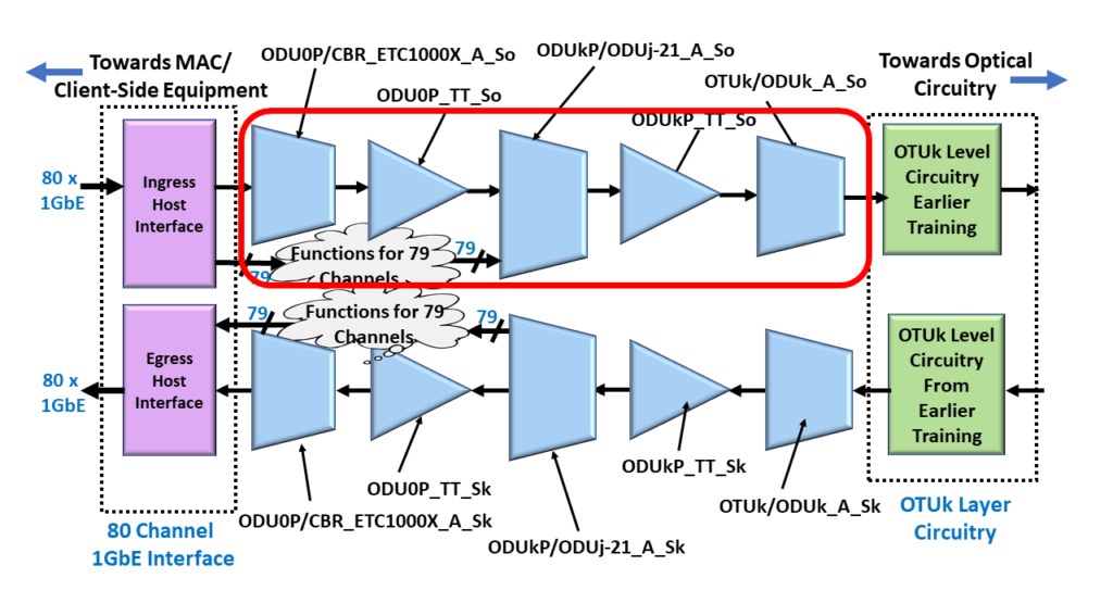
Figure 1, Illustration of the ODU4/OTU4 System, with the Atomic Functions that we discuss in Video 2 highlighted

You Can Also Check Out the Video Below:

Click HERE to Go to Video 2 – The OTUk/ODUk_A_Sk and ODUk_TT_Sk Atomic Functions

Click HERE to return to the Main Lesson 10 Page – Multiplexed Applications

Resources, Corrections, and Additional Information about this Post

Resources Page - Lesson 10 - ODU Layer Defect Handling and Performance Monitoring Requirements

Resources – OTN Lesson 10

Resources - OTN Lesson 10 - ODU Layer Defect Handling and Performance Monitoring Requirements This page contains links to various ...
The Forum

The Forum Page

The Best Darn OTN Training ... Period - Forum This page serves as a place-holder for the Forum. The Forum ...
Mistakes and Corrections to OTN Lesson 10 - ODU Layer Defects and Performance Monitoring Requirements

OTN – Lesson 10 – Mistakes/Corrections

OTN Lesson 10 - ODU Layer Defects and Performance Monitoring Requirements - Mistakes/Corrections This page identifies any mistakes and corrections ...

What is Running Disparity (RD)?

The Running Disparity (or RD) is defined as the difference between the number of logic 1 bits and logic 0 bits between the start of a data sequence and a particular instant in time during its transmission.


What is Running Disparity (RD)?

We define the Running Disparity (or RD) as the difference between the number of logic 1 bits and logic 0 bits between the start of a data sequence and a particular instant in time during its transmission.

In other words, the RD for a character is the difference between the number of logic 1 bits and logic 0 bits in that character.

Hence, if there are more logic 1 bits than logic 0 bits (within a character or string of consecutive bits), we can state that the RD is positive.

If there are more logic 0 bits than logic 1 bits, then we can state that the RD is negative.

Finally, if the number of logic 1 and logic 0 bits are the same, we can state that the RD is neutral or zero.

We can express the Running Disparity as either an integer or as a ratio:

EXPRESSING RD AS AN INTEGER NUMBER:

If you wish to express the RD of a character or string (of consecutive bits) as an integer number, then you can calculate the RD with the following equation:

RD = (Number of Logic 1 bits in the character or string) – (Number of Logic 0 bits in the character or string)

For example:  

The running disparity of the hexadecimal expression of 0x78 is 0.

To understand why this is the case, if we were to express this value in its binary format, we get 0111 1000.  The binary expression (for this value) contains four 0s and four 1s.

Thus, RD = 4 – 4 = 0

On the other hand, the running disparity of the hexadecimal expression of 0x7F is +6.

Again, if we were to express this value in its binary format, we would get 0111 1111.  The binary expression (for this value) contains seven 1s and one 0.

Hence, RD = 7 – 1 = +6

EXPRESSING RD AS A RATIO:

If you wish to express the RD of a character or string (of consecutive bits) as a ratio, then you would do the following:

  • Count the total number of logical “1s” in the expression.
  • Count the total number of logical “0s” in the expression.

And then express this information in the following format:

Number of Logical 1s (in character/string) :  Number of Logical 0s (in character/string)

For example:

We express the running disparity of the hexadecimal expression of 0x78 as:

4:4, which we can reduce (or simplify) to 1:1.

Likewise, we can compute and express the RD for the value 0x7F as
7:1.

Some communication and data storage system standards (such as Gigabit Ethernet/1000BASE-X, Fibre-Channel, etc.) require that we maintain the RD as near to neutral as possible.

The system designer must ensure that the ratio of logical 1 bits to logical 0 bits (over time) should be kept close to 1:1.

Thus, the System Designer must follow any character/string with negative disparity with another character/string with an equal amount of positive disparity, and vice-versa.

Keeping RD to a minimum is to maintain dc balance on the transmission medium.

The System Designer must ensure that the RD does not increase without bounds.

The 8B/10B line code is a specific example of a line code that requires and exercises control over RD.

NOTE:  Controlling and monitoring RD can also help detect transmission errors.

Has Inflaton got You Down? Our Price Discounts Can Help You Fight Inflation and Help You Become an Expert on OTN!! Click on the Banner Below to Learn More!!

Discounts Available for a Short Time!!!