This blog post briefly defines the Source Address field, within the Ethernet Frame.
Introduction
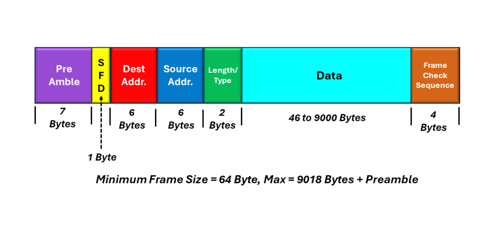
The Source Address field is a 6-byte (48-bit) field that occurs just after the Destination Address within the Ethernet frame.
I show an illustration of the IEEE 802.3 (Basic) Ethernet frame, with the Source Address field highlighted below in Figure 1.
Figure 1, Illustration of the IEEE 802.3 (Basic) Ethernet frame, with the Source Address field highlighted
Comparison to the Destination Address Field
When I was discussing the Destination Address field, I mentioned that the Destination Address field contains the address location, or the Ethernet station/port that we are sending the Ethernet frame to.
In contrast, the Source Address field contains the address of the Ethernet station, that is generating/transmitting the Ethernet frame.
Further, where the Destination Address field can contain either a Unicast (or Physical) Port Address, a Multicast, or the Broadcast Address; the Source Address field ONLY contains the Unicast (or Physical) Port Address.
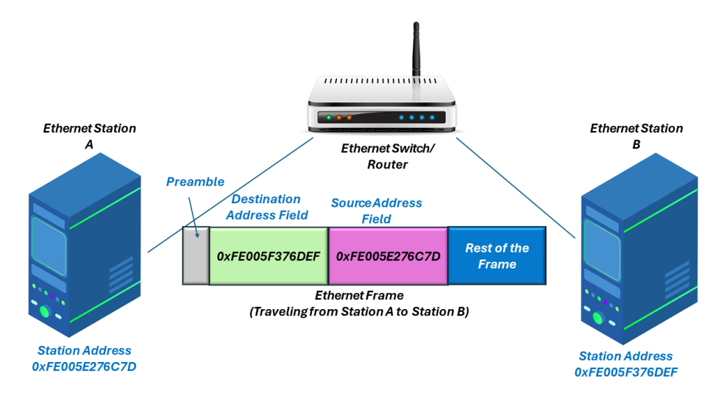
In Figure 2, I show an Ethernet station (with MAC Address 0xFE005E276C7D) sending an Ethernet frame another Ethernet station (within MAC Address 0xFE005F376DEF). I also show (how the Destination and Source Address fields, within the frame, relates to the Ethernet station addresses.
Figure 2, Ethernet station A (with MAC Address =0xFE005E276C7D) sends an Ethernet frame to Ethernet Station B (with MAC Address = 0xFE005F376DEF).
Ethernet Hardware Processing of the Source Address Field
In most cases, Ethernet switching and routing circuitry does not pay too much attention the Source Address field, within each Ethernet frame. This hardware is almost always more focused on the value of the Destination Address (and making sure the Ethernet frames are properly switched throughout the network).
However, there are cases where the Ethernet Circuitry will use and evaluate the Source Address field. Some of these cases include troubleshooting problems. Additionally, the Ethernet equipment will pay attention to the Source Address field, whenever a new router (or switch) powers up and it needs to build up a routing table (e.g., a table that associates switch ports with Ethernet addresses).
In another blog post, I discuss the Address Resolution Protocol, in which the Source Address field comes in handy.
Nonethless, the Source Address field does not typically undergo near the evaluation and processing as does the Destination Address.
This blog post defines and describes the role of the Destination Address field within the Ethernet Frame.
Introduction
The Destiination Address is a 6-byte (or 48-bit) field that follows the Preamble, within the Ethernet frame.
Whenever an Ethernet station transmits an Ethernet frame to one (or more other stations), the Destination Address identifies the intended recipient or recipients of this Ethernet frame. In other words, the Destination address identifies which station should receive this Ethernet frame.
Figure 1 shows an illustration of the IEEE 802.3 (Basic) Ethernet frame, with the Destination Address highlighted.
Figure 1, Illustration of the IEEE 802.3 (Basic) Ethernet frame, with the Destination Address highlighted.
Each Ethernet interface (or Station) is assigned a unique 48-bit address. We sometimes call this 48-bit Address the Physical, Hardware or MAC Address.
The Destination Address field (within the Ethernet frame) contains either:
The 48-bit Ethernet address that corresponds to the address of the Ethernet interface in the station (which is the destination of the frame).
As the Ethernet Receiver receives Ethernet frames, it reads the contents of every frame up to the Destination Address field. If the Destination Address value does not match the Interface’s own Ethernet address or one of the multicast or broadcast addresses that the interface is programmed to receive, then the Ethernet Receiver will ignore the rest of the Ethernet frame.
Conversely if the Destination Address value DOES match the interface’s own Ethernet address, or one of the multicast or broadcast addressse (that the interface is programmed to receive), then the Ethernet Receiver will accept and process the rest of the Ethernet frame.
The DIX Standard and the IEEE 802.3 Standards handle/interpret the Destination Address field slightly differently, as I describe below.
The DIX Standard for the Destination Address
We use the first bit of the Destination Address field (as transmitted onto the network medium) to distinguish physical addresses from multicast (or broadcast) addresses.
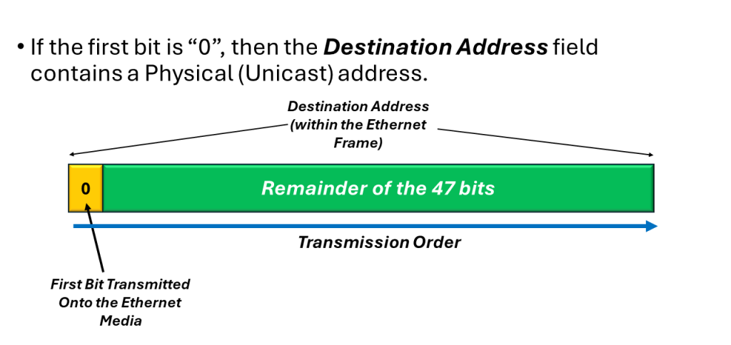
If this first bit (transmitted within the Destination Address) is zero (0), then the Destination Address field contains the physical address of an interface (or Station). We also refer to this address as the unicast address because we only send this Ethernet frame to this address only.
In Figure 2, I show an illustration of a simple “Unicast Address” within the Destination Address field.
Figure 2, Illustration of a Simple “Unicast (or Physical) Address within the Destination Address field.
Please note that in Figures 2, 3 and 4, I am showing the Transmission Order of the bits, within the Destination Address (when one Ethernet station is transmitting an Ethernet frame to another station). I will discuss the bit-ordering (within an Ethernet frame) and how we transmit bits (within the Destination Address) from one Ethernet station to another station, below.
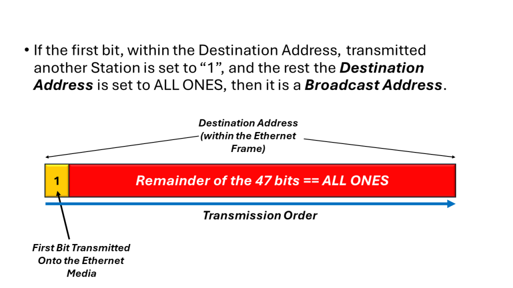
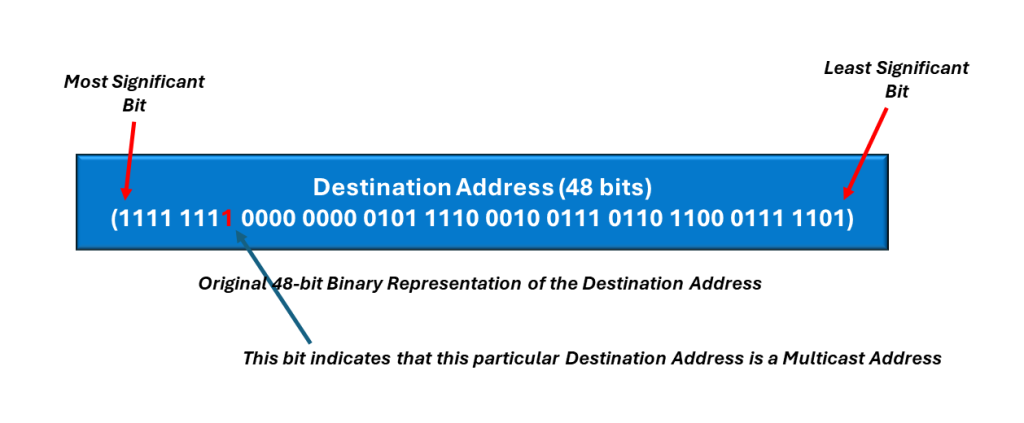
If the first bit (based on the transmission order onto the medium) is a one (1), then the Destination Address field contains a multicast address. If all 48-bits are set to “1” (e.g., an All Ones pattern), then the Destination Address field contains a broadcast (or all stations) address.
In Figure 3, I show a simple illustration of the Multicast Address, within the Destination Address field.
Figure 3, Illustration of the Multicast Address, within the Destination Address field.
In Figure 4, I show a simple illustration of the Broadcast Address, within the Destination Address field.
Figure 4, Illustration of the Broadcast Address, within the Destination Address field.
The IEEE 802.3 Standard for the Destination Address
The IEEE 802.3 standard (for the Destination Address field) interprets the first bit (transmitted within the Destination Address) the same way as for the DIX standard frames. However, IEEE 802.3 adds significance to the second bit within the Destination Address.
In this case, we use this second bit-field to distinguish between locally and globally administered addresses.
A globally administrated address is a physical address that an Ethernet Equipment Manufacturer assigned to the interface. If the network sets this 2nd bit-field is set to “0”, then this is a globally administered address.
NOTE: In the DIX Standard, we always globally administer Destination Addresses.
If the Ethernet Interface address is administered locally, then the second bit is typically set to “1”.
For example, in the case of the Broadcast Address, the 2nd bit, along with all other bits (within the Destination Address) are set to “1” in both the DIX and IEEE 802.3 standards.
NOTE: We rarely use Locally administered addresses in Ethernet networks. These days Ethernet Equipment Manufacturers assign each piece of Ethernet equipment its own unique 48 -bit Ethernet address during manufacturing. As I discuss in another blog post, these addresses are globally administered.
How We Transmit the Contents of the Destination Address
As I mentioned earlier, the Destination Address field consist of 6-bytes or 48-bits. To show the transmission order (along with the rest of the Ethernet frame), it is best to show an example.
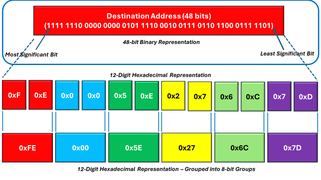
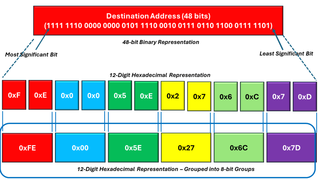
Consider an Ethernet frame with the following Destination Address (below in the highlighted portion of Figure 5).
Figure 5, Illustration of the Breakdown of the Destination Address field
The length of the Destination Address is 48 bits (or 6 bytes). If we were to divide the bits (within this 48-bit field) into twelve (12) Nibbles, then you can express the contents within the Destination Address as 12 hexadecimal values – as I show below in the middle portion of Figure 6.
Figure 6, The Destination Address expressed as 12 (4-bit) Hexadecimal Values
We can then combine these 12 Hexadecimal bytes into 6 (two-digit) Hexadecimal Values. When we do that, then we can express the Destination Address as follows:
Figure 7, The Destination Address expressed as 6 (2 Digit) Hexadecimal Values
These 6 (2 Digit) Hexadecimal Values (of the Destination Address) are also the 6 bytes within the Desitination Address field.
The Transmission Order of the Destination Address
To transmit an Ethernet frame onto the media, we take the left-most byte (the byte in the red field) and then reverse the order of this byte (transmitting the right-most bit – within this particular byte first). We then proceed to transmit the remaining bits within this byte (all the way to the left-most bit). Next, we use the same procedure for the next byte (just to the right of this left-most byte, in the light blue field).
Figure 8 illustrates the resulting transmission order of the Destination Field, within the Ethernet frame.
Figure 8, The Transmission Order of the Destination Field, within the Ethernet field.
Determining Whether the Destination Address is a Unicast, Multicast or Broadcast Address
I mentioned that the network determines whether the Destination Address field is a Unicast, Multicast, or Broadcast address by the state of the very first bit (within the Destination Address field) that we place on the Ethernet media and transmit to the other station(s).
We stated that if the network sets this particular bit-field to “0”, then we are transmitting a Unicast Address. In Figure 9, I show that this particular Destination Address (that we are transmitting) is indeed a Unicast Address (because this first bit is set to “0”.
Figure 9, Illustration of the Destination Field, highlighting the Unicast/Multicast bit-field(Not in Transmission Order)
In Figure 9, we also show the location of this particular bit-field, within the Destination Field of the Ethernet frame. Once again, I show that we are transmitting a Unicast Address.
In Figure 10, I show an example of a Multicast Address (residing within the Destination Address field) of the Ethernet frame.
Figure 10, An Example of a Multicast Address within the Destination Address field of the Ethernet frame (Not in Transmission Order)
Finally, in Figure 11, I show an example of the Broadcast Address (residing within the Destination Address field) of the Ethernet frame.
Figure 11, Example of the Broadcast Address within the Destination Address field of the Ethernet frame. (Not in Transmission Order)
This blog post presents a brief description of the contents and role of the Preamble, within the Ethernet frame.
The Preamble is the first 64 bytes within each Ethernet frame.
In Figure 1, I show an illustration of the Ethernet frame, with the Preamble Highlighted.
Figure 1, Illustration of the Ethernet frame with the Preamble Highlighted.
The original purpose of the Preamble was to provide an Ethernet Receiver or Station (which is just starting to receive an Ethernet frame) a sequence of bits to allow for it to synchronize itself with this incoming data before it receives the actual important data within the frame.
Some Background
In early 10Mbps Ethernet, stations would only receive data from other stations when one station sent a frame to the other stations.
When there was no data to send, the stations transmitted nothing, and the line was mostly quiet.
In Figure 2, I illustrate two Ethernet stations connected, transmitting no data to each other.
Figure 2, Illustration of two Ethernet stations, connected, transmitting no data to each other.
In this quiet condition, the line (or the Ethernet connection) between the two stations is quiet, and there are almost no electrical signals or activity on the line.
Then, when a station starts to send an Ethernet frame to another station, it first sends a preamble to wake up the receiving station and allow that station to synchronize itself with the incoming data stream (which is the Ethernet frame).
A More Technical Discussion
Stated more technically, each Ethernet station (capable of receiving an Ethernet frame) has some sort of Clock-Recovery PLL (or Phase-Locked Loop). The whole purpose of the Preamble (preceding the Ethernet frame) was to allow the receiving circuitry (within the PLL) to receive this sequence of bits (or transitions within the data) and obtain synchronization with this incoming data stream (or Ethernet frame) before the important data starts to arrive (e.g., the Destination Address).
What is this Preamble?
The Preamble is mostly a repeating sequence, with a repeating “1010…” pattern. The length of this preamble is 64 bits (or 8 bytes).
Again, the purpose of this Preamble (back in the old days) was to place a sequence of electrical (or optical) transitions (e.g., repeating 1010… data) within an Ethernet line and (effectively wake up the Ethernet receiver) before the receiving station actually receives useful and meaningful information (that it needs to receive and interpret properly).
In Figure 3, I show a close-up illustration of the Preamble within an Ethernet frame.
Figure 3, Illustration of the Preamble within an Ethernet frame.
Figure 3 shows that the Preamble consists of 7 bytes of the value: 0xAA or 10101010 in binary format. However, the last byte within the Preamble is of value 0xAB (or 10101011 in binary format).
Hence, the Preamble is mostly a repeating 1010.. pattern, lasting for 64 bits (or 8 bytes).
However, depending upon which Ethernet standard you are using, the standard defines that last byte (within the Preamble) differently, as I discuss below.
The DIX Frame (or Standard)
The DIX Standard defines this entire 8-byte sequence (or 0xAA, 0xAA, 0xAA, 0xAA, 0xAA, 0xAA, 0xAA, 0xAB) as the Preamble.
I show the definition of the Preamble (per the DIX Standard) in Figure 4.
Figure 4, DIX Definition of the Preamble.
IEEE 802.3 Frame (or Standard)
The IEEE 802.3 standard defines the Preamble as 7 bytes of the repeating 0xAA strings. However, it defines the last byte of the Preamble (the byte with the value 0xAB – as the Start of Frame Delimiter (SFD) byte.
I show the definition of the Preamble (per the IEEE 802.3 standard) below in Figure 5.
Figure 5, IEEE 802.3 Definition of the Preamble
Important Things to Note about the Preamble
Whether operating in the DIX Standard or the IEEE 802.3 standard, the Preamble (or the sequence of data that stations transmit BEFORE each Ethernet frame) is the same between the two standards.
Additionally, both standards require the 8th byte to have a value of 0xAB (or 10101011 in binary format). This particular byte (known as the Start of Frame Delimiter byte in the IEEE 802.3 standard) alerts the receiving Ethernet station that the Preamble is about to end and that the very next byte is part of the Destination Address.
I show the IEEE 802.3 (Basic) Ethernet Frame format in Figure 6 below, which illustrates my last point.
Figure 6, Illustration of the IEEE 802.3 Standard (Basic) Ethernet frame.
Are Preambles Still Used in Ethernet Frames?
In modern Ethernet, we have constructed our high-speed Ethernet data-streams to behave more like CBR (or Constant Bit Rate) signals, rather than bursty streams of traffic (with long idle periods between the reception of Ethernet frames). Hence, the Preamble no longer functions as a warm-up string of data to synchronize the receiver to the incoming Ethernet frame.
However, IEEE has kept the Preamble within the Ethernet standard documents. They chose to do this in order to maintain some backward compatibility between the various flavors/types of Ethernet.
IEEE has largely kept the IEEE 802.3 (Basic) Ethernet frame, exactly the same, over the decades of development within Ethernet technology.
This blog post presents a brief description of the IEEE 802.3 (Basic) Ethernet frame. It also identifies differences between this frame and the DIX Frame.
in 1985, the Institute of Electrical and Electronic Engineers (IEEE) published their first IEEE 802.3 standard, defining their own version of the Ethernet Frame.
Over time, there were some changes to this Ethernet frame structure, and the current IEEE 802.3 (Basic) Ethernet frame is as shown below in Figure 1.
Figure 1, The IEEE 802.3 (Basic) Frame Structure/Format.
Why the Word “Basic”?
I include the word “Basic” to differentiate this format of the Ethernet frame from other IEEE 802.3 formats, such as:
These other two frames have also been standardized in IEEE 802.3. However, each of these frame formats are different from each other.
Very Similar to the DIX Frame
The IEEE 802.3 (Basic) Ethernet frame is almost identical to the DIX frame.
It can have a minimum frame length of 64 bytes and a maximum frame length of 1518 bytes (not including the Preamble). Hence, the length of this frame is identical to that of the DIX Frame.
Preamble Differences
In reality, the Preamble of the IEEE 802.3 frame is identical to that of the DIX Frame. However, the IEEE Committees have defined the Preamble differently than the DIX Consortium.
I illustrate the Preamble (within the IEEE 802.3 Basic Ethernet frame) in Figure 2.
Figure 2, Illustration of the Preamble (within the IEEE 802.3 Basic Ethernet frame).
The IEEE 802.3 Standard defines the Preamble as a 7-byte field (each byte with the value of 0xAA (or 10101010 – in binary format). This standard also defines the 8th byte (of the Preamble) as a Start of Frame Delimiter (SFD). In this case, the SFD byte always has the value of 0xAB (or 10101011 – in binary format).
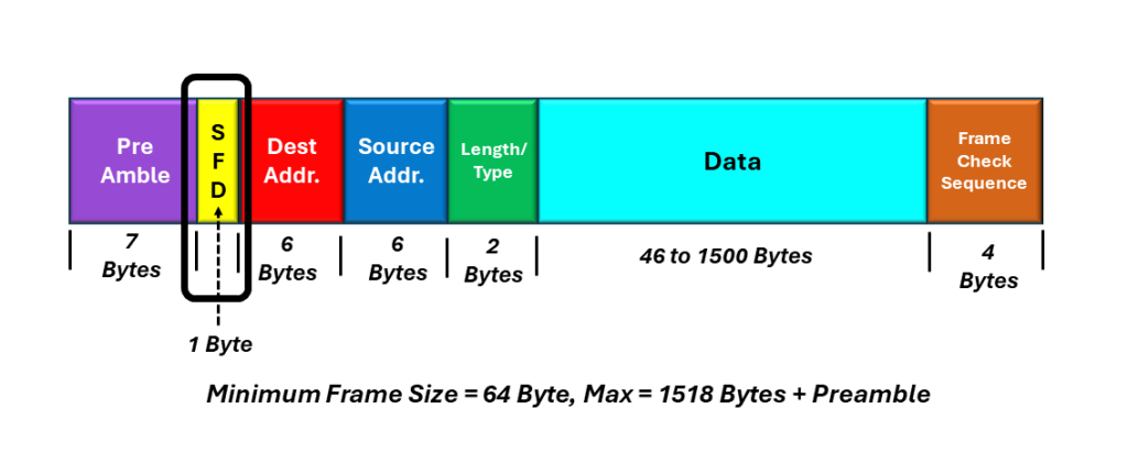
I show an illustration of the IEEE 802.3 (Basic) Ethernet frame format, with the SFD byte highlighted below in Figure 3.
Figure 3, Illustration of the IEEE 802.3 (Basic) Ethernet frame format, with the SFD byte highlighted.
Please note that although the DIX and IEEE standards define the Preamble differently, if you look closely at the byte values (of the Preamble), the Preamble for the DIX Frame and the Preamble plus SFD for the IEEE frame are identical.
The Length/Type Field
Another difference between the DIX and the IEEE 802.3 frames is in the Type or Length/Type field.
I show an illustration of the IEEE 802.3 (Basic) Ethernet frame, with the Length/Type field highlighted in Figure 4.
Figure 4, Illustration of the IEEE 802.3 (Basic) Ethernet frame format, with the “Length/Type” field highlighted.
The first version of the IEEE 802.3 standard (published in 1985) defined this particular field as the Length field. However, in 1997, the IEEE 802.3 Committee changed this field to the Length/Type field, to be compatible with the DIX Standard.
How Does the Length/Type Field Work?
The current standards define the Length/Type field as follows:
If the Length/Type field value is 1500 (or 0x05DC in Hexadecimal)
If the Length/Type field is 1500 or less (or 0x05DC in hexadecimal), then this 16-bit field will function as the Length field. The value of the Length/Type field will then reflect the number of octets within the Data field of the Ethernet frame.
If the Length/Type field value is greater than 1536 (or 0x0600 in Hexadecimal) – Compatible with DIX Frame
If the Length/Type field is greater than 1536 (0x0600 in hexadecimal), then this 16-bit field will function as a Type field. In this case, the value of the Length/Type field indicates the type of protocol data that the Ethernet frame is carrying (similar to DIX frames).
In another blog post, I present a list of standard values for the Length/Type field (when the value is greater than 1536), along with their meaning.
I identify the location of the Preamble within the DIX frame below in Figure 2.
Figure 2, The Location of the Preamble within the DIX Frame.
The main difference between the Preamble, within the DIX Frame, and that within the IEEE 802.3 (Basic) Frame is how they are defined.
I also show the byte format of the Preamble within the DIX frame below in Figure 3.
Figure 3, The Byte-format of the Preamble within the DIX Frame.
I will list the characteristics/features of the Preamble below.
Consists of 8-bytes
The first seven (7) bytes contain the value of 10101010
The 8th byte contains the value: 10101011
The last two bits (of the Preamble) are set to “[1, 1,]” to denote the end of the Preamble and the start of the Destination Address field.
The Type Field
I show the location of the Type field (within the DIX Frame), below in Figure 4.
Figure 4, Illustration of the Location of the Type-Field within the DIX Frame.
In the DIX Standard, the Type field is a 16-bit field containing an identifier that indicates the type of high-level protocol data we are carrying within the Data Field of the Ethernet Frame.
For example, if the Type field is set to 0x0800, then the Data Field (within this particular Ethernet frame) is transporting data that supports the IP (Internet Protocol).
In another blog post, I present a list of standard values for the Type field.
The IEEE 802.3 (Basic) and the other IEEE 802.3-compliant Ethernet frames all use the Type/Length for this 2-byte position within the Ethernet frame.
I have defined the Destination Address, Source Address, Data Field, and Frame Check Sequence fields in other blog posts.
This blog post presents an overview of the various types of Ethernet frames, that are in use today.
The purpose of this blog post is to list, itemize, and briefly describe the various types of Ethernet frames that are in use today.
This blog post will also provide links to blog posts with more details about these various Ethernet frames and the various fields (within these frames).
In short, there are five different types of Ethernet frames (that are widely used in networking today).
We call this type of a frame a “Q-Tag” frame, because it includes the IEEE 802.1Q Tag. The literature also calls this tag the VLAN or priority tag. We discuss VLAN (Virtual LANs) in another post.
I illustrate the IEEE 802.3 Compliant Frame with Q-Tag below in Figure 3.
Figure 3, Illustration of the IEEE 802.3 Compliant Frame with Q-Tag.
The maximum length of the IEEE 802.3 Frame (with Q-Tag) is 1522 bytes (plus Preamble).
I present a more detailed description of the IEEE 802.3 Compliant Frame – with Q-Tag, in another blog post.
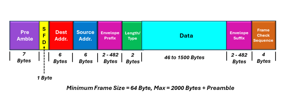
IEEE 802.3 Complaint Ethernet Frame with Envelope Prefix and/or Suffix
I illustrate the IEEE 802.3 Compliant Ethernet Frame with Envelope Prefix and/or Suffix, below in Figure 4.
Figure 4, Illustration of the IEEE 802 Compliant Ethernet Frame with Envelope Prefix and/or Suffix
The IEEE 802.3 Compliant – Envelope Frames, can have a maximum length of 2000 bytes (plus the Preamble).
I present a more detailed description of the IEEE 802.3 Compliant Ethernet frame with Envelope Prefix and Suffix in another blog post.
Jumbo Frame
I illustrate the Jumbo Frame before in Figure 5.
Figure 5, Illustration of the Jumbo Frame
The Jumbo Frame can be a large as 9018 bytes (in length) plus the Preamble.
I present a more detailed description of the Jumbo Ethernet frame in another blog post.
This blog post describes how the Receive STS-1 Framer uses the SEF/LOF Declaration Clearance State Machine diagram to acquire and maintain STS-1 Frame Synchronization.
Introduction
An STS-1 Network Element relies on the A1 and A2 bytes within the Section Overhead (SOH) to acquire and maintain STS-1 Frame Synchronization.
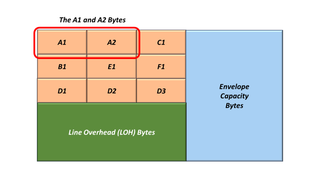
Figure 1 illustrates the Section Overhead bytes with the A1 and A2 bytes highlighted.
Figure 1, Illustration of the SOH with the A1 and A2 bytes highlighted.
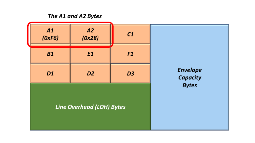
Whenever an STS-1 Transmitter (or STE) generates and transmits an STS-1 frame, it will always set the A1 and A2 bytes to the following values:
A1 = 0xF6
A2 = 0x28
I show an additional drawing of SOH, with the values for A1 and A2 filled in.
Figure 2, Illustration of the SOH with the A1 and A2 bytes set to their actual values.
Receive STS-1 Framer Tries to Acquire STS-1 Frame Synchronization
The Receive STS-1 Framer (at the remote end of the network – receiving this STS-1 signal) will search for and locate the A1 and A2 bytes (within its incoming STS-1 data stream). As the Receive STS-1 Framer receives this signal, it will attempt to acquire and maintain STS-1 Frame Synchronization with this incoming STS-1 data stream.
A given STE (receiving this STS-1 signal) will declare and clear either of the following defect conditions based on its ability to receive the A1 and A2 bytes.
dSEF – Severely Erred Frame Defect
dLOF – Loss of Frame Defect
The SEF/LOF Defect Declaration/Clearance State Machine
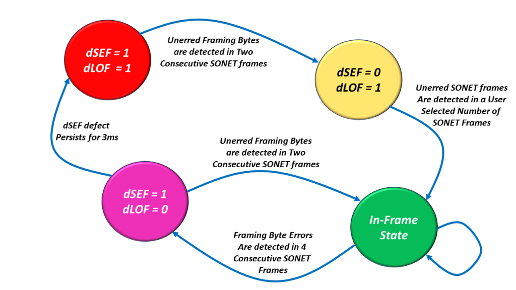
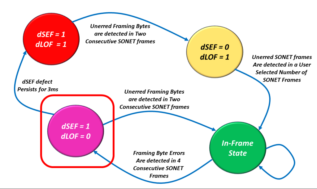
The decision to declare and clear the dSEF and/or dLOF Defects is best understood by reviewing the SEF/LOF Defect Declaration/Clearance State Machine Diagram. I show this diagram below in Figure 3.
Figure 3, Illustration of the SEF/LOF Declaration/Clearance State Machine Diagram.
You can see that the SEF/LOF Declaration/Clearance State Machine Diagram contains the following four states.
The In-Frame (or SEF = 0/LOF = 0) State (the Most Desirable State to Operate in).
The SEF = 1/LOF = 0 State (Declaring the SEF – Severely Erred Frame defect condition).
The SEF = 1/LOF = 1 State (SONET Framer has not located the A1 and A2 bytes at all), and
The SEF = 0/LOF = 1 State (The SONET Framer has cleared the SEF defect and is now trying to clear the LOF defect condition).
Let’s Take a Walk through the SEF/LOF Declaration/Clearance State Machine Diagram
Let’s start at the “SEF = 1/LOF = 1” state.
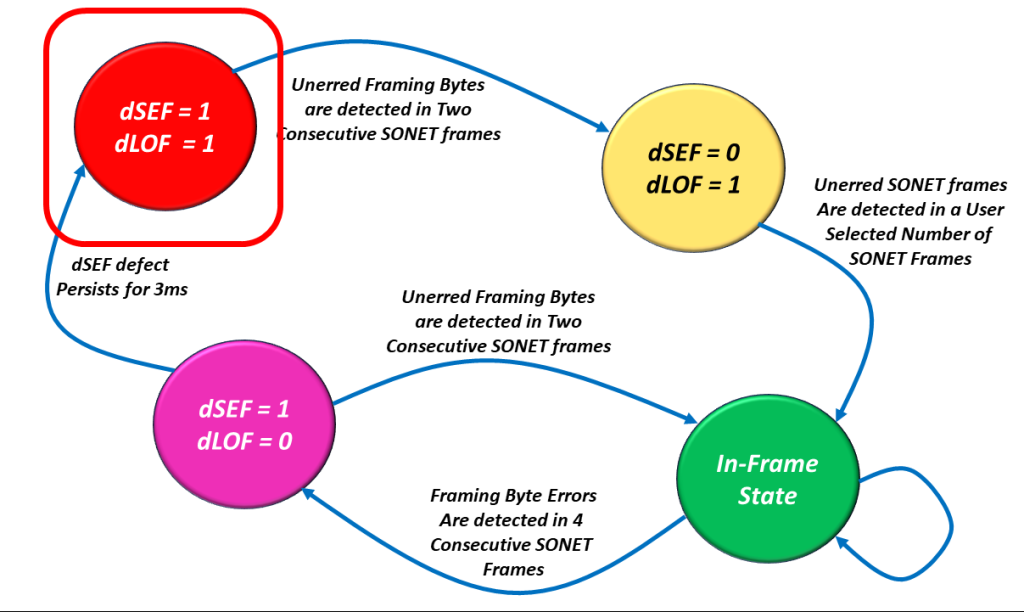
The dSEF = 1/dLOF = 1 State
I show a drawing of the SEF/LOF Declaration/Clearance State Machine Diagram with the SEF = 1/LOF = 1 state highlighted in Figure 4.
Figure 4, Illustration of the SEF/LOF Declaration/Clearance State Machine Diagram – with the SEF = 1/LOF = 1 state highlighted.
We hope the Receive STS-1 Framer is rarely operating in this state.
Let’s assume (and hope) that the Receive STS-1 Framer only operates in this state upon system power-up. Shortly after power-up, the Receive STS-1 Framer will operate in this state as it receives an STS-1 Data Stream.
As it receives this STS-1 Data Stream, it will parse this incoming data stream and search for the A1 and A2 bytes.
Once it locates (what it believes) are the A1 and A2 bytes (e.g., a string with the value 0xF628), it will note this location and search again exactly 810 bytes (e.g., one STS-1 frame period) later.
At this later period, if it determines that the framing pattern (e.g., 0xF628) is NOT present, then the Receive STS-1 Framer will assume that it was momentarily fooled by data bytes mimicking the A1 and A2 bytes.
On the other hand, if the Receive STS-1 Framer detects the framing alignment pattern again (exactly 810 bytes after finding it the first time), then it will believe that it is on to something and transition into the dSEF = 0/dLOF = 1 state.
NOTE: In this case, the Framer will transition into the dSEF = 0/dLOF = 1 state after the Framer has correctly detected the A1 and A2 bytes in two consecutive STS-1 frames.
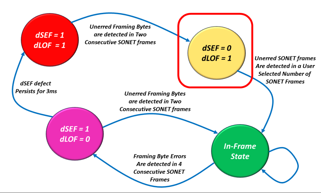
The dSEF = 0/dLOF = 1 State
I show a drawing of the SEF/LOF Declaration/Clearance State Machine Diagram with the dSEF = 0/dLOF = 1 state highlighted in Figure 5.
Figure 5, Illustration of the SEF/LOF Declaration/Clearance State Machine Diagram – with the dSEF = 0/dLOF = 1 state highlighted.
Once in this state, the Receive STS-1 Framer block will clear the dSEF (Severely Erred Frame) alarm. It will also continue to check the incoming A1 and A2 bytes for the Framing Pattern.
Telcordia GR-253-CORE states that “the SONET NE shall terminate a LOF defect 1ms to 3ms after terminating the SEF defect on the incoming SONET signal if the SEF defect is not (re) detected before the LOF defect is terminated.”
This is why we labeled the transition (from the dSEF = 0/dLOF = 1 State to the In-Frame State) as “Unerred SONET Frames Are Detected in a User Number of SONET Frames“.
The user can select the criteria for clearing the dLOF defect to be either 1 ms or 3 ms when operating in the dSEF = 0 condition, provided that the dSEF condition is not re-declared during that period.
Either way, if the SONET NE can meet these requirements, it will transition into the In-Frame State.
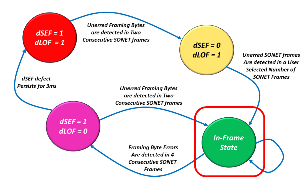
The In-Frame State
I show a drawing of the dSEF/dLOF Declaration/Clearance State Machine Diagram with the In-Frame state highlighted in Figure 6.
Figure 6, Illustration of the dSEF/dLOF Declaration/Clearance State Machine Diagram – with the In-Frame State Highlighted.
We hope that the Receive STS-1 Framer will operate in this state for most of its lifetime.
When the Receiver STS-1 Framer circuitry is operating in this state, the SONET NE can now do its other processing of STS-1 frames (checking for B1 bytes errors, using the H1 and H2 bytes to search for the SPE, etc.).
All of these things are possible whenever the Receiver STS-1 Framer is operating in this state. None of these things are possible if the Receiver STS-1 Framer is not operating in this state.
Is it possible for Bad Things to Happen such that We Have to Leave this State?
Yes, all good things can and sometimes do come to an end.
In other words, it is possible for bad things to happen that will cause the Receive STS-1 Framer to leave the In-Frame state.
If the Receive Framer were to detect FA1/FA2 errors within 4 consecutive STS-1 Frame, then it would declare the dSEF defect condition and transition into the dSEF = 1/dLOF = 0 state.
The dSEF = 1/dLOF = 0 State
I show a drawing of the dSEF/dLOF Declaration/Clearance State Machine Diagram with the dSEF = 1/dLOF = 0 state highlighted in Figure 7.
Figure 8, Illustration of the SEF/LOF Declaration/Clearance State Machine Diagram – with the SEF = 1/LOF = 0 State Highlighted.
If the Receive STS-1 Framer transitions into this state, then one of two things can happen from here.
The Good Option
The burst of errors could go away, and the Receive STS-1 Framer block could (then) detect two consecutive STS-1 Framers with NO FA1/FA2 byte errors.
If this occurs, the Receive STS-1 Framer block will clear the dSEF defect and transition back to the In-Frame state, also known as the Good State. Once again, I show a drawing of the dSEF/dLOF Declaration/Clearance State Machine Diagram with the In-Frame state highlighted in Figure 9.
Figure 9, Illustration of the dSEF/dLOF Declaration/Clearance State Machine Diagram – with the dSEF = 0/dLOF = 0 State Highlighted.
And there is the Bad Option.
The Bad Option
The burst of errors persists, and the Receive STS-1 Framer continues to operate continuously in the dSEF Condition for 3 ms. When this occurs, then the Receive STS-1 Framer will declare the dLOF defect, and we will transition back into the dSEF = 1/dLOF = 1 state.
In What States will the Receive STS-1 Framer declare the dLOF Defect Condition?
The Receive STS-1 Framer block will declare the dLOF defect condition whenever it is operating in the following two states:
dSEF = 1/dLOF = 1
dSEF = 0/dLOF = 1
In short, whenever dLOF = 1, then the Receive STS-1 Framer block declares the dLOF (Loss of Frame) defect condition.
In What States is the Receive STS-1 Framer NOT declaring the dLOF Defect Condition
The Receive STS-1 Framer block will clear the dLOF defect condition whenever it is operating in the following two states:
In-Frame
dSEF = 1/dLOF = 0
In short, whenever dLOF = 0, then the Receive STS-1 Framer clears the dLOF defect condition.
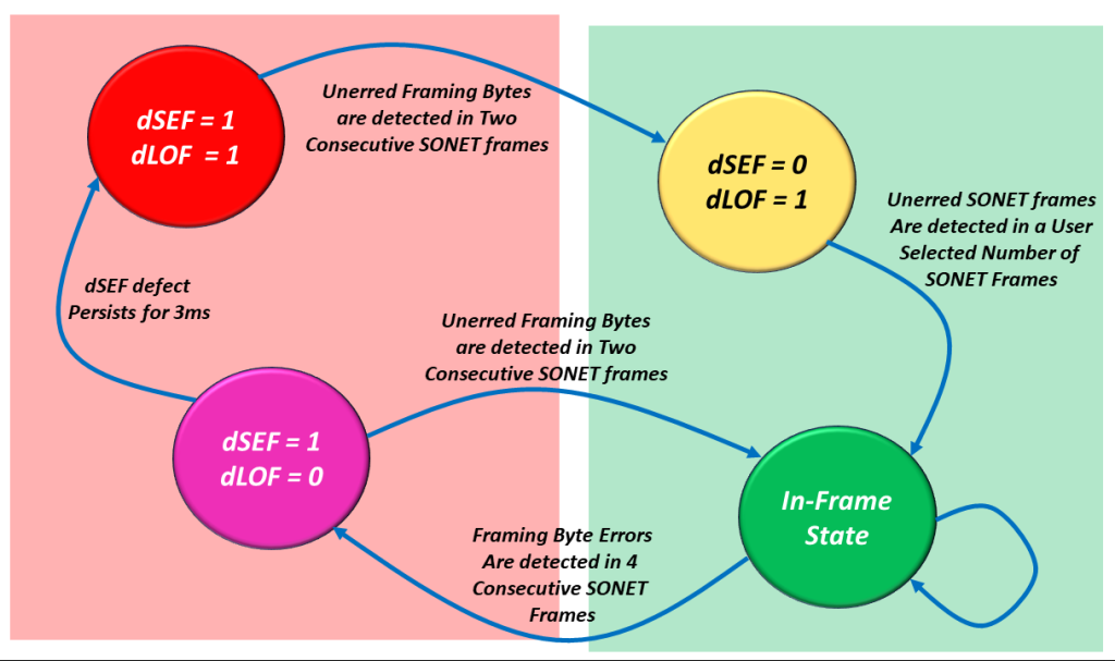
In Figure 10, I illustrate the SEF/LOF Declaration/Clearance State Machine Diagram, with two states immersed in green shade and the other two in red shade.
Figure 10, Illustration of the SEF/LOF Declaration/Clearance Machine Diagram – In which states will the Receive STS-1 Frramer declare or clear the dLOF defect condition.
The two states immersed in the Green Shade are those states in which the Receive STS-1 Framer will clear the dLOF defect condition.
On the other hand, the states immersed in the Red Shade are those states in which the Receive STS-1 Framer will declare the dLOF defect condition.
This concludes our introduction to the SEF/LOF Declaration/Clearance State Machine.
This blog post describes both the Envelope Capacity and the Synchronous Payload Envelope wtihin an STS-1 Frame.
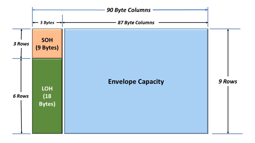
In an earlier blog post, I showed a simple drawing of an STS-1 Frame. In this drawing, I show the SOH (Section Overhead) and the LOH (Line Overhead). I show this simple drawing again below in Figure 1.
Figure 1, Simplified Drawing of the STS-1 Frame.
I have also briefly defined and discussed these byte fields in other posts.
This blog post will briefly discuss the STS-1 Envelope Capacity and the Synchronous Payload Envelope.
In Figure 1, you clearly see the Envelope Capacity within the STS-1 Frame. It is clearly marked and takes up much of the STS-1 Frame.
Where is the Synchronous Payload Envelope (SPE)?
Figure 1 also shows the SPE, but you don’t see it labeled in the Figure.
What is the Purpose of the Envelope Capacity within the STS-1 Frame?
The purpose of the Envelope Capacity is to transport the client (or user) data.
What is the Purpose of the SPE within the STS-1 Frame?
The purpose of the SPE is to transport the client (or user) data.
So, the Envelope Capacity and the SPE have the exact same purpose.
Where is the SPE?
So, Where is the SPE?
The SPE and the Envelope Capacity are (sort of) one and the same. The SPE has the same role/function as the Envelope Capacity.
Further, the SPE is located within the Envelope Capacity. And you can argue that the Envelope Capacity is located within the SPE.
Location of the Envelope Capacity (within the STS-1 Frame)
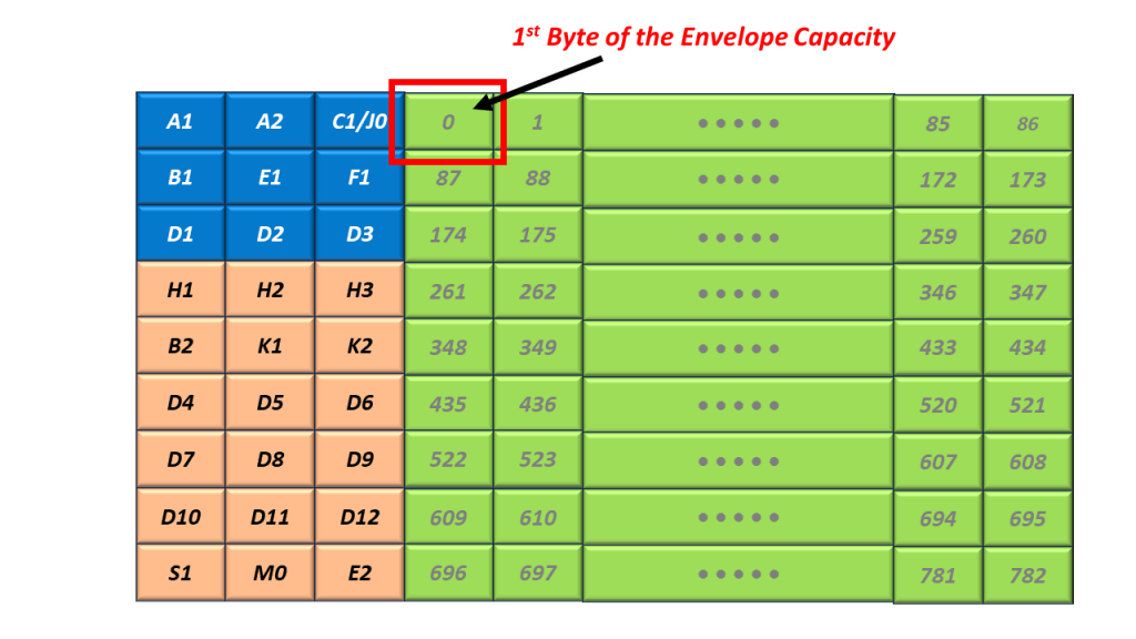
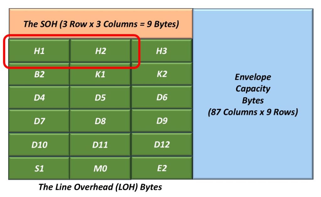
The Envelope Capacity begins with the byte just to the right of the C1/J0 Byte (within the SOH). I show the location of the first byte within the Envelope Capacity in Figure 2.
Figure 2, Illustration of the Very First Byte within the Envelope Capacity
Figure 2 also shows that Byte 1 (the 2nd byte within the Envelope Capacity) is located just to the right of Byte 1, and so on.
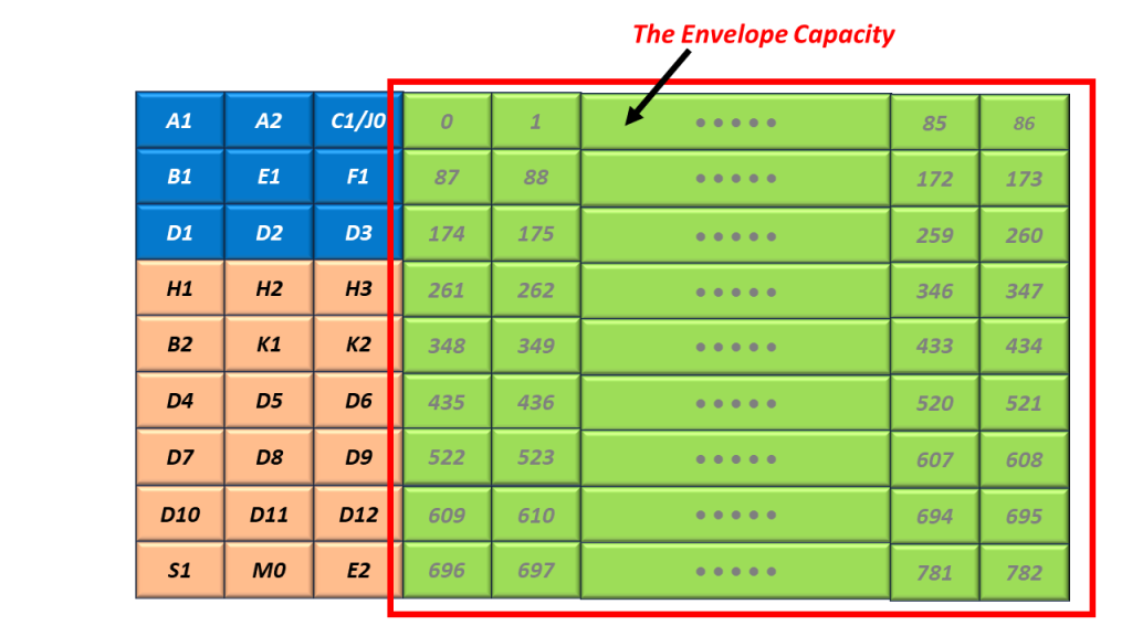
I show the Byte Numbering scheme for the Envelope Capacity below in Figure 3.
Figure 3, Byte-Numbering Scheme within the Envelope Capacity, within an STS-1 Frame (from Bytes 0 to Byte 782).
So, Where is the SPE?
The SPE is located in the exact same space as the Envelope Capacity. However, its Byte Numbering Scheme is different.
I show a drawing of the SPE below in Figure 4.
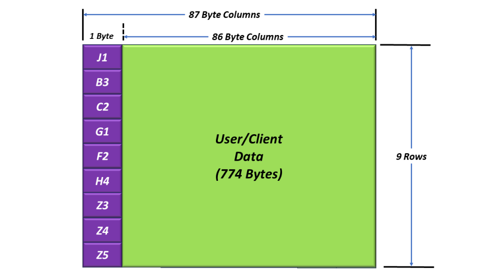
Figure 4, The SPE (Synchronous Payload Envelope)
Figure 4 shows the SPE (e.g., the Payload or User Data) along with the Nine Path Overhead (POH) bytes located in the left-most column (of the SPE). This figure also shows that the STS-1 SPE is a 9 Row x 87 Byte Column Structure (the same size as the Envelope Capacity).
Figure 4 also shows that the very first byte of the SPE is the J1 byte (located in the upper left-hand corner of the SPE).
What is the Byte-Numbering Scheme of the SPE within an STS-1 Frame
So, What is the Byte-Numbering Scheme of the SPE within an STS-1 Frame
The Byte-Numbering scheme differs for the STS-1 SPE from what we showed for the Envelope Capacity.
In the case of the Envelope Capacity, Byte 0 is located just to the right of the C1/J0 byte (within the SOH), as I stated earlier. Further, Byte 0 (within the Envelope Capacity is always in that same location (just East of the C1/J0 byte).
In the case of the SPE, Byte 0 (e.g., the J1 byte) is located wherever the Pointer Bytes (H1 and H2) say that it is. The H1 and H2 bytes permit the SONET Receiver to locate the SPE within the STS-1 frame.
The main difference between the SPE and the Envelope Capacity is that the location of the Envelope Capacity is fixed (Byte 0 is always located just East of the C1/J0 Byte).
In the case of the SPE, Byte 0 (the J1 byte within the POH) can “float” anywhere within the Envelope Capacity.
The Envelope Capacity and the SPE have the same roles and are of the same size (e.g., 783 bytes). However, the location of the Envelope Capacity is fixed and aligned with the SOH and LOH bytes within the STS-1 Frame.
The location of the SPE is not fixed (with respect to the SOH and LOH bytes) and can float. This means that the SPE can begin within any of the 783 bytes within the Envelope Capacity.
I discuss the roles of the H1, H2, and H3 bytes and the location of the SPE (within the Envelope Capacity) in another blog post.
However, in Figures 5, 6, 7, and 8, I show a couple of possible locations of the SPE (within the Envelope Capacity).
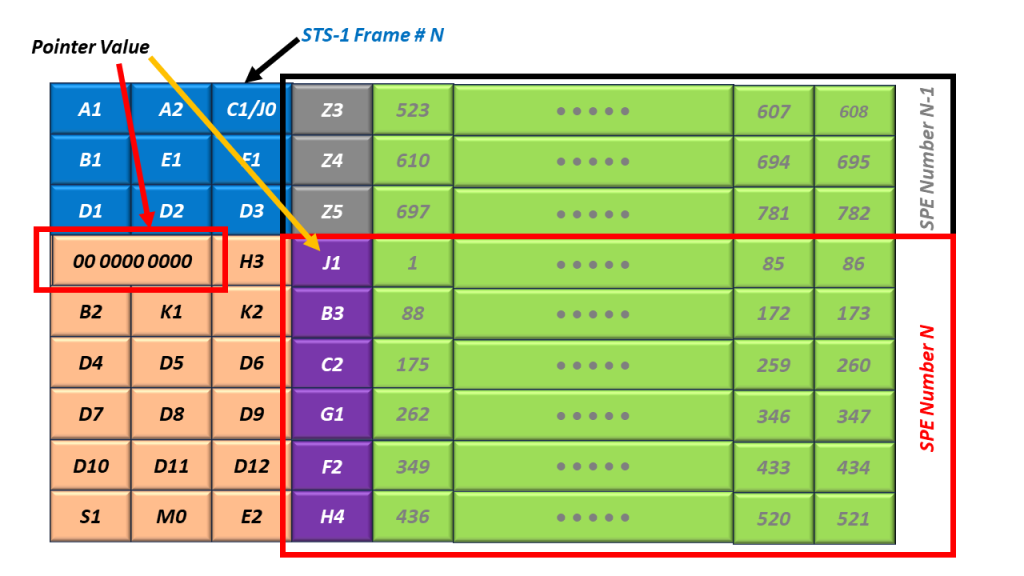
Figure 5, Illustration of the SPE, located at Byte 0 (just to the right of the H3 byte) – STS-1 Frame N.
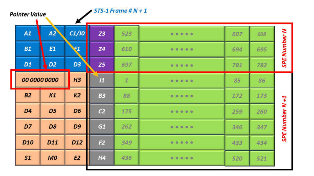
Figure 6, Illustration of the SPE (again located at Byte 0) – STS-1 Frame N+1.
In Figures 5 and 6, I also show that the pointer’s value (within the H1 and H2 bytes) is 0. In this case, the SPE begins at Byte 0 (the Byte just to the right of the H3 byte).
Please note that the SPE will often straddle across two consecutive STS-1 frames. Figure 5 shows the location of the SPE within STS-1 Frame N. Further, Figure 6 shows the location of the same SPE within the next frame (STS-1 Frame N+1).
Figure 7, Illustration of the SPE, located at Byte 522 (just to the right of the C1/J0 byte).
In Figure 7, I show that the value of the H1 and H2 bytes are 522 (0x020A). In this case, the SPE happens to be (accidentally) aligned with the SOH and LOF of the STS-1 Frame and located just to the right of the C1/J0 byte.
What Do the Pointer Values (within the H1 and H2 Bytes) Mean?
Finally, I show the Byte Numbering Scheme for SPEs in Figure 8.
Figure 8, What the Values of the H1 and H2 Bytes Mean – for the location of the J1 Byte within the SPE.
In other words, Figure 8 presents the relationship between the value of the Pointers (within the H1 and H2 byte) and the location of the J1 Byte (within the SPE) within the STS-1 Frame.
Figure 8 shows that a Pointer Value of 0 corresponds with the STS-1 SPE starting at the byte, just to the right of the H3 Byte. I show an example of an SPE at this location in Figures 5 and 6.
This same figure also shows that a Pointer Value of 522 corresponds with the STS-1 SPE starting at the byte, just to the right of the C1/J0 byte. I show an example of an SPE at this location in Figure 7.
Why Don’t We Fix the Location of the SPE within the STS-1 Frame?
One important difference that the SPE has (from that of the Envelope Capacity) is that the location of the SPE can move from time to time. We refer to events (in which the SPE changes its location within the STS-1 Frame) as Pointer Adjustment events.
Whenever these Pointer Adjustment events occur, the values within the Pointer Bytes (e.g., the H1 and H2 bytes) will change. The SONET Network uses pointer adjustment to accommodate timing differences throughout the network.
I will discuss the H1, H2, H3 bytes, and Pointer Adjustments in another blog post.
This blog post briefly describes/defines the roles/functions of the Line Overhead Bytes within a SONET signals.
The Line Layer
The Line Layer is the second highest layer within the SONET Reference Model.
The purpose of the Line Layer is to support the transmission of data between the Source and Sink Terminal of a given STS-N signal.
Figure 1 presents an illustration of some STS-1 and STS-3 circuitry that helps to define the Line.
Figure 1, Definition of an STS-N Line
In Figure 1, I show that an STS-3 Line Signal begins and ends at the STS-1 to the STS-3 MUX/DeMUX block (which originates and terminates the STS-3 signal).
What is an LTE – Line Terminating Equipment
Any piece of equipment that manages the transmission and reception of an STS-N data stream, from the point that we create this signal to the point where we terminate this signal.
An LTE will manage the transmission and reception of STS-N data via the Line Overhead (LOH) bytes.
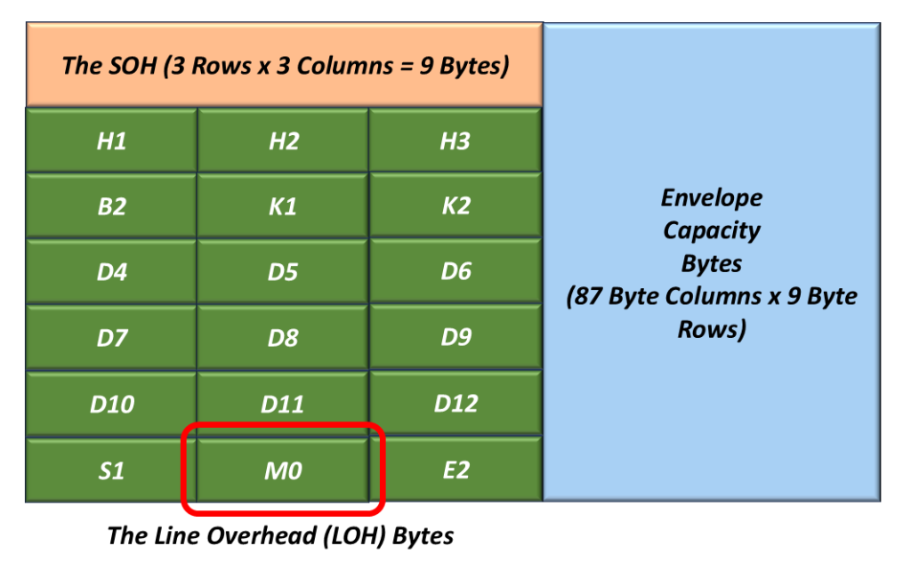
The LOH bytes reside in (and are a subset of) what we often refer to as the “Transport Overhead” (TOH) bytes. Figure 2 illustrates the Line Overhead Bytes within an STS-1 Signal.
Figure 2, Illustration of the Line Overhead Bytes within an STS-1 Signal.
All LTEs are also STEs
Therefore, all LTEs will manage the transmission and reception of STS-N data via both the “SOH” and “LOH” bytes.
We briefly define the SOH bytes (within an STS-1 frame) in another blog post.
Description of the Line Overhead (LOH) Bytes
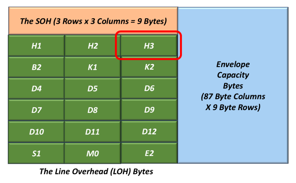
H1 and H2 Pointer Bytes
Figure 3 highlights the location of the H1 and H2 bytes within the LOH.
Figure 3, The Location of the H1 and H2 bytes within the LOH
The contents of the H1 and H2 bytes are used to indicate the offset between the location of these bytes and the first byte within the STS-1 Synchronous Payload Envelope (SPE).
An STS-1 Transmitter will compute a 10-bit pointer value and will insert this data into the H1 and H2 bytes within a given “outbound” STS-1 frame.
An STS-1 Receiver will use this 10-bit pointer to locate the SPE within the incoming STS-1 data stream.
I present a more detailed discussion of the H1 and H2 bytes in another blog post.
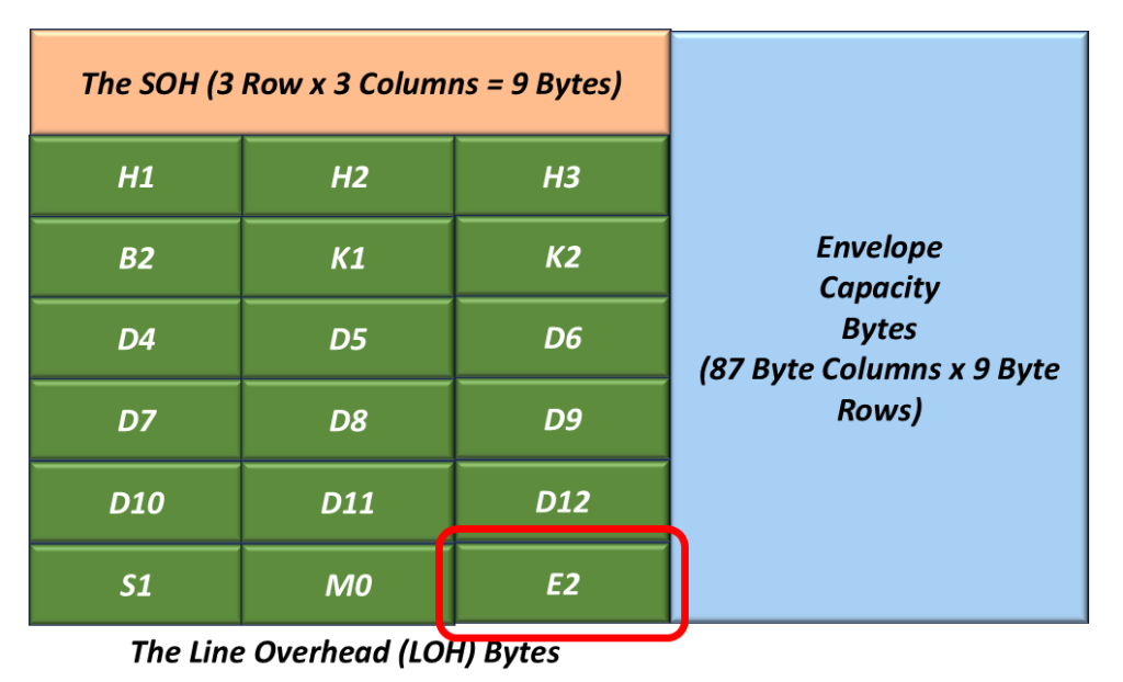
H3 Pointer Action Byte
Figure 4 highlights the location of the H3 byte within the LOH.
Figure 4, The Location of the H3 byte within the LOH.
We typically use the H3 byte for “Frequency” or “Pointer Justification” purposes.
I present a more detailed discussion of the H3 byte in another blog post.
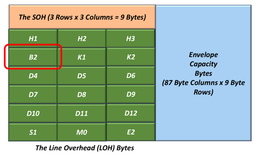
The B2 Byte
Figure 5 presents the location of the B2 byte within the LOH.
Figure 5, The Location of the B2 Byte within the LOH.
The Role of the Transmit STS-1 Terminal – B2 Byte
A Transmitting STS-1 Terminal will compute the contents of the B2 byte by performing a BIP-8 calculation over all bits within the LOH and the Envelope Capacity within a given “outbound” STS-1 frame (after scrambling).
This resulting byte value is inserted into the B2 Byte field (within the very next outbound STS-1 frame) before scrambling (of the current STS-1 frame).
The Role of the Receive STS-1 Terminal – B2 Byte
As a Receiving STS-1 Terminal receives the LOH and the Envelope Capacity data (within a given STS-1 frame), it will compute its own BIP-8 value.
Afterwards, the Receive STS-1 Terminal will compare the value of its “locally” computed BIP-8 value with the value residing within the B2 byte-field of the very next STS-1 frame.
If the two values are the same, then the Receive STS-1 Terminal will “conclude” that it has received the LOH and Envelope Capacity data in an un-erred manner.
If the two values are different, then the Receive STS-1 Terminal will “conclude” that it received the LOH and Envelope Capacity in an erred manner.
We will discuss how SONET STEs should flag the occurrence of B2 byte errors in a future blog post.
NOTES:
The B2 byte (in SONET) is analogous to the Section BIP within an OTU Frame.
We will discuss how the Transmit STS-1 Terminal computes the B2 byte and how the Receive STS-1 Terminal verifies the B2 byte in another blog post.
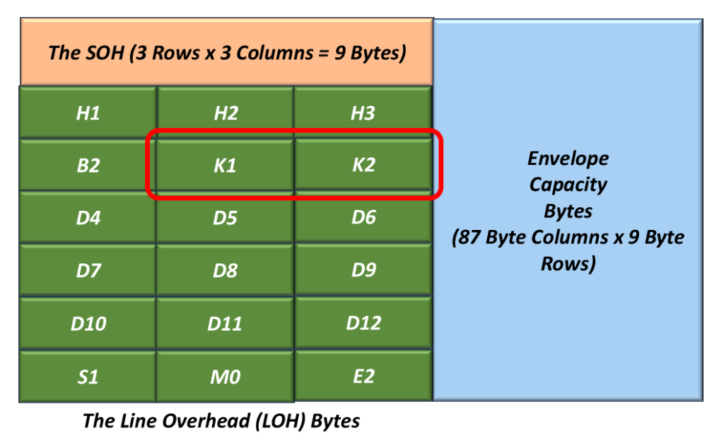
The K1 and K2 (Automatic Protection Switching) Bytes
Figure 6 highlights the location of the K1 and K2 bytes within the LOH.
Figure 6, The Location of the K1 and K2 Bytes within the LOH.
The SONET Protocol uses the K1 and K2 bytes for the following purposes:
To transport the APS signaling protocol (Used in BLSR and Linear APS schemes).
A given LTE will use the K1 and K2 bytes to detect/clear the following defect conditions within a SONET signal.
AIS-L (Line AIS) Defect
RDI-L (Line – Remote Defect Inidicator).
We will discuss the APS Protocol in another blog post.
We will also discuss how the SONET Terminal transmits and declares the AIS-L and RDI-L defect conditions in another post.
The Line Data Communication Channel (D4 through D12) Bytes
Figure 7 highlights the location of the Line Data Communication Channel Bytes within the LOH
Figure 7, The Location of the Line DCC (Data Communication Channel) Bytes – D4 through D12 within the LOH
The D4 through D12 bytes are located in the first STS-1 of an STS-N and are considered as one 576kbps message-based channel for alarms, maintenance, control, monitoring and administering, and other communication needs.
This channel is available for internally generated, externally generated, and supplier-specific messages.
I will discuss what I mean by the expression: “the first STS-1 of an STS-N” in another blog post.
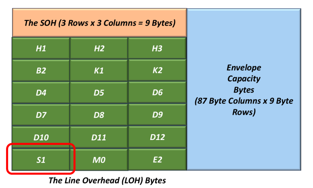
The S1 – Synchronization Status Byte
Figure 8 presents the location of the S1 Byte within the LOH.
Figure 8, Illustration of the LOH with the S1 Byte Highlighted
We use this byte to transport the Synchronization Status Message (SSM).
I will discuss how we use the S1 byte in another blog post.
This blog post briefly defines the Section Overhead bytes within the SONET Frame.
The Section Layer and the Section Overhead (SOH) Bytes
The Section Layer involves transporting an STS-N data stream across the physical medium (e.g., copper or optical fiber) in a point-to-point manner (e.g., between any two adjacent pieces of equipment).
The purpose of the Section Layer is to ensure that the STS-N data stream, which is being transported over a given link or coaxial cable or optical fiber, is properly received.
Functions within this layer include:
Framing
Scrambling
Error detection
Section-Level Communications Overhead, such as the local orderwire.
Data Communication Channels (DCC) to carry information for OAM & P (Operation, Administration, Maintenance, and Performance).
The Section Terminating Equipment (STE)
We refer to any piece of equipment that manages the transmission and reception of STS-N data over a single link of optical fiber or coaxial cable as an STE (Section Terminating Equipment).
An STE will manage the transmission and reception of STS-N data via the Section Overhead (SOH) bytes.
The Section Overhead (SOH) Bytes
The SOH bytes reside in (and are a subset of) what we refer to as the “Transport Overhead” (TOH) bytes.
Figure 1 illustrates the SONET STS-1 Frame, with the SOH and LOH bytes field identified.
Figure 1, Another Look at the SONET STS-1 Frame – SOH and LOH Bytes Highlighted.
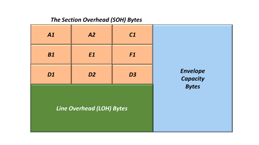
I show and identify the Section Overhead (SOH) bytes in Figure 2 below.
Figure 2, Illustration and Identification of the Section Overhead Bytes
I will briefly describe the SOH bytes below.
The A1 and A2 (Framing Alignment) Bytes
In Figure 3, I show the location of the A1 and A2 bytes within the SOH.
Figure 3, Location of the A1 and A2 Bytes within the Section Overhead
The A1 and A2 bytes are the Framing Alignment bytes.
These two bytes are assigned the following values:
A given STS-1 Transmitter will always set the A1 and A2 bytes to these specific values.
The STS-1 Receiver (receiving this STS-1 signal) will search for and locate the “A1” and “A2” bytes to acquire and maintain STS-1 Frame Synchronization within this incoming STS-1 data stream.
A given STS-1 (receiving an STS-1 signal) will declare either of the following defect conditions based on its success in receiving the A1 and A2 bytes.
dSEF – Severely Erred Frame
dLOF – Loss of Frame
The STE will declare/clear the SEF and LOF Defect by using the “SEF/LOF Defect Declaration/Clearance – State Machine” diagram, which I show in Figure 4.
Figure 4, Illustration of the SEF/LOF Declaration/Clearance State Machine Diagram
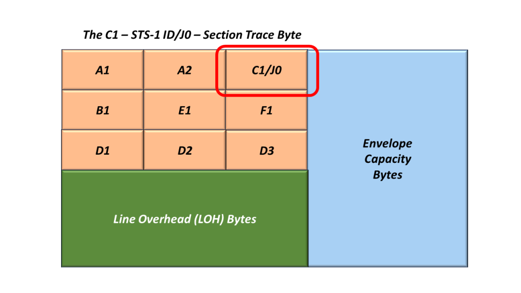
In Figure 5, I show the location of the C1 within the SOH.
Figure 5, Location of the C1/J0 Byte, within the Section Overhead
This Byte-Field serves two possible roles:
The C1 Byte (STS-1 ID)
In earlier editions of GR-253-CORE, the C1 byte was allocated to function as an “STS-1 ID” function.
The C1 byte is no longer used for this purpose.
However, to ensure interoperability with older SONET equipment, this byte must be capable of transmitting and receiving the “STS-1 ID” number.
The J0 Byte – Section Trace Byte
The STE uses this byte to repetitively transmit a 1, 16, or 64-byte message so that the receiving STE can verify its continued connection to the intended transmitting sTS-1 STE.
NOTE: This is similar to the Trail Trace Identifier fields within the OTU and ODU frames.
The B1 (Section BIP-8) Byte
In Figure 6, I present the location of the B1 byte within the STS-1 SOH.
Figure 6, Location of the B1 Byte within the STS-1 SOH.
The Role of the Transmit STS-1 Terminal
A Transmitting STS-1 Terminal will compute the contents of the B1 byte by performing a BIP-8 calculation over all bits within a given “outbound” STS-1 frame (after scrambling).
This byte value is inserted into the B1 Byte field (within the very next outbound STS-1 frame) before scrambling (of the current STS-1 frame).
The Role of the Receive STS-1 Terminal
As a Receiving STS-1 Terminal receives this STS-1 signal, it will compute its own BIP-8 value.
Afterward, the Receive STS-1 Terminal will compare its “locally” computed BIP-8 value with the value residing within the B1 byte field of the next STS-1 frame.
If the two values are the same, then the Receive STS-1 Terminal will “conclude” that it has received this STS-1 signal in an un-erred manner.
If the two values are different, then the Receive STS-1 Terminal will “conclude” that it received this STS-1 signal in an erred manner.
We will discuss how SONET STEs should check for and flag the occurrence of B1 byte errors in a future blog post.
NOTE: The B1 byte (in SONET) is analogous to the Section BIP within an OTU Frame.
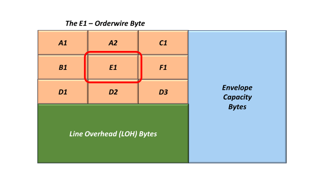
The E1 (Orderwire) Byte
Figure 7 presents the location of the E1 byte within the STS-1 SOH.
Figure 7, Location of the E1 Byte within the STS-1 SOH.
We refer to this byte as the Section Order-Wire Byte.
The Standard Committee allocated this byte for use as a local order wire channel for voice communication between regenerators, hubs, and remote terminal locations.
The F1 (Section User Channel) Byte
Figure 8 presents the location of the F1 byte within the STS-1 SOH.
Figure 8, Location of the F1 Byte within the STS-1 SOH.
The Standard Committee set aside the F1 byte for the user’s purposes.
This byte is passed from STE to STE over the STS-N transmission media.
This byte can typically be written into/read from at any STE.
Use of this byte is optional.
The D1, D2 and D3 (Section Layer – Data Communication Channel) Bytes
Figure 9 presents the location of the Section Layer Data Communication Channel (DCC) bytes within the STS-1 SOH.
Figure 9, Location of the Section Layer DCC Bytes within the STS-1 SOH.
These three bytes form a 192kbps message channel that supports transmitting OAM & P (Operation, Administration, Maintenance, and Provisioning) messages between pieces of Section Terminating Equipment.
ANSI.105.04 defines the protocols that we use in the Section Layer DCC.
Examples of STE (Section Terminating Equipment
Regenerators
Defects that occur within the Section Layer
dLOS – Loss of Signal
dSEF – Severely Erred Frame
dLOF – Loss of Frame
I briefly define and describe the Line Overhead Bytes (within a SONET Signal) in another blog post.
I also describe the Envelope Capacity and Synchronous Payload Envelope (SPE) in yet another blog post.