
The Section Layer and the Section Overhead (SOH) Bytes
The Section Layer involves transporting an STS-N data stream across the physical medium (e.g., copper or optical fiber) in a point-to-point manner (e.g., between any two adjacent pieces of equipment).
The purpose of the Section Layer is to ensure that the STS-N data stream, which is being transported over a given link or coaxial cable or optical fiber, is properly received.
Functions within this layer include:
- Framing
- Scrambling
- Error detection
- Section-Level Communications Overhead, such as the local orderwire.
- Data Communication Channels (DCC) to carry information for OAM & P (Operation, Administration, Maintenance, and Performance).
The Section Terminating Equipment (STE)
We refer to any piece of equipment that manages the transmission and reception of STS-N data over a single link of optical fiber or coaxial cable as an STE (Section Terminating Equipment).
An STE will manage the transmission and reception of STS-N data via the Section Overhead (SOH) bytes.
The Section Overhead (SOH) Bytes
The SOH bytes reside in (and are a subset of) what we refer to as the “Transport Overhead” (TOH) bytes.
Figure 1 illustrates the SONET STS-1 Frame, with the SOH and LOH bytes field identified.
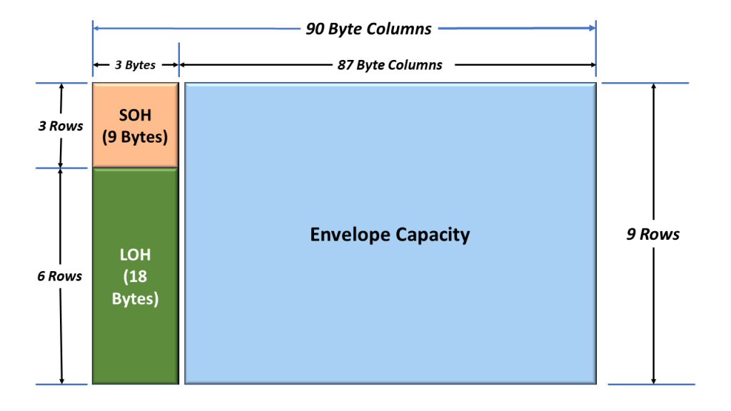
Figure 1, Another Look at the SONET STS-1 Frame – SOH and LOH Bytes Highlighted.
I show and identify the Section Overhead (SOH) bytes in Figure 2 below.
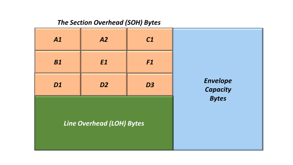
Figure 2, Illustration and Identification of the Section Overhead Bytes
I will briefly describe the SOH bytes below.
The A1 and A2 (Framing Alignment) Bytes
In Figure 3, I show the location of the A1 and A2 bytes within the SOH.
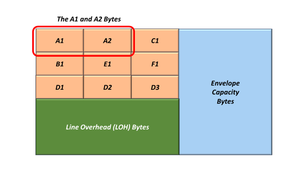
Figure 3, Location of the A1 and A2 Bytes within the Section Overhead
The A1 and A2 bytes are the Framing Alignment bytes.
These two bytes are assigned the following values:
- A1 = 0xF6, and
- A2 = 0x28
NOTE: These values are the same as the FA1 and FA2 bytes within the OTU frame.
A given STS-1 Transmitter will always set the A1 and A2 bytes to these specific values.
The STS-1 Receiver (receiving this STS-1 signal) will search for and locate the “A1” and “A2” bytes to acquire and maintain STS-1 Frame Synchronization within this incoming STS-1 data stream.
A given STS-1 (receiving an STS-1 signal) will declare either of the following defect conditions based on its success in receiving the A1 and A2 bytes.
- dSEF – Severely Erred Frame
- dLOF – Loss of Frame
The STE will declare/clear the SEF and LOF Defect by using the “SEF/LOF Defect Declaration/Clearance – State Machine” diagram, which I show in Figure 4.
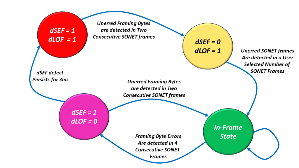
Figure 4, Illustration of the SEF/LOF Declaration/Clearance State Machine Diagram
NOTE: We discuss the SEF/LOF Declaration/Clearance State Machine Diagram (and how the STE declares the dSEF or dLOF defect) in another blog post.
The C1 (STS-1 ID)/J0 (Section Trace Message) Byte
In Figure 5, I show the location of the C1 within the SOH.
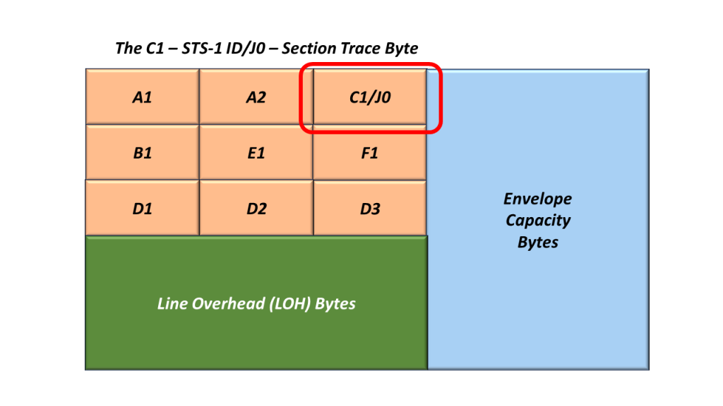
Figure 5, Location of the C1/J0 Byte, within the Section Overhead
This Byte-Field serves two possible roles:
The C1 Byte (STS-1 ID)
In earlier editions of GR-253-CORE, the C1 byte was allocated to function as an “STS-1 ID” function.
The C1 byte is no longer used for this purpose.
However, to ensure interoperability with older SONET equipment, this byte must be capable of transmitting and receiving the “STS-1 ID” number.
The J0 Byte – Section Trace Byte
The STE uses this byte to repetitively transmit a 1, 16, or 64-byte message so that the receiving STE can verify its continued connection to the intended transmitting sTS-1 STE.
NOTE: This is similar to the Trail Trace Identifier fields within the OTU and ODU frames.
The B1 (Section BIP-8) Byte
In Figure 6, I present the location of the B1 byte within the STS-1 SOH.

Figure 6, Location of the B1 Byte within the STS-1 SOH.
The Role of the Transmit STS-1 Terminal
A Transmitting STS-1 Terminal will compute the contents of the B1 byte by performing a BIP-8 calculation over all bits within a given “outbound” STS-1 frame (after scrambling).
This byte value is inserted into the B1 Byte field (within the very next outbound STS-1 frame) before scrambling (of the current STS-1 frame).
The Role of the Receive STS-1 Terminal
- As a Receiving STS-1 Terminal receives this STS-1 signal, it will compute its own BIP-8 value.
- Afterward, the Receive STS-1 Terminal will compare its “locally” computed BIP-8 value with the value residing within the B1 byte field of the next STS-1 frame.
- If the two values are the same, then the Receive STS-1 Terminal will “conclude” that it has received this STS-1 signal in an un-erred manner.
- If the two values are different, then the Receive STS-1 Terminal will “conclude” that it received this STS-1 signal in an erred manner.
- We will discuss how SONET STEs should check for and flag the occurrence of B1 byte errors in a future blog post.
NOTE: The B1 byte (in SONET) is analogous to the Section BIP within an OTU Frame.
The E1 (Orderwire) Byte
Figure 7 presents the location of the E1 byte within the STS-1 SOH.
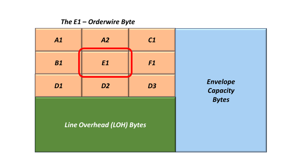
Figure 7, Location of the E1 Byte within the STS-1 SOH.
We refer to this byte as the Section Order-Wire Byte.
The Standard Committee allocated this byte for use as a local order wire channel for voice communication between regenerators, hubs, and remote terminal locations.
The F1 (Section User Channel) Byte
Figure 8 presents the location of the F1 byte within the STS-1 SOH.

Figure 8, Location of the F1 Byte within the STS-1 SOH.
The Standard Committee set aside the F1 byte for the user’s purposes.
This byte is passed from STE to STE over the STS-N transmission media.
This byte can typically be written into/read from at any STE.
Use of this byte is optional.
The D1, D2 and D3 (Section Layer – Data Communication Channel) Bytes
Figure 9 presents the location of the Section Layer Data Communication Channel (DCC) bytes within the STS-1 SOH.

Figure 9, Location of the Section Layer DCC Bytes within the STS-1 SOH.
These three bytes form a 192kbps message channel that supports transmitting OAM & P (Operation, Administration, Maintenance, and Provisioning) messages between pieces of Section Terminating Equipment.
ANSI.105.04 defines the protocols that we use in the Section Layer DCC.
Examples of STE (Section Terminating Equipment
Regenerators
Defects that occur within the Section Layer
- dLOS – Loss of Signal
- dSEF – Severely Erred Frame
- dLOF – Loss of Frame
I briefly define and describe the Line Overhead Bytes (within a SONET Signal) in another blog post.
I also describe the Envelope Capacity and Synchronous Payload Envelope (SPE) in yet another blog post.