The SONET Reference Model
In the OSI (Open System International) Reference Model, we attempted to describe and understand a communications network via a seven (7) layer model. This model consists of the following layers.
- The Application Layer
- The Presentation Layer
- The Session Layer
- The Transport Layer
- The Network Layer
- The Data Link Layer
- The Physical Layer
In SONET, we attempt to describe and understand communication networks via a four (4) layer model (which we call the SONET Reference Model).
In order of decreasing complexity, we have the following layers.
- The Path Layer
- The Line Layer
- The Section Layer and
- The Physical Layer
We will briefly describe each of these layers below.
In Figure 1, I show a drawing with some pieces of Optical Transmission Equipment. I also show where each of these four SONET Layers fit in between these pieces of equipment.
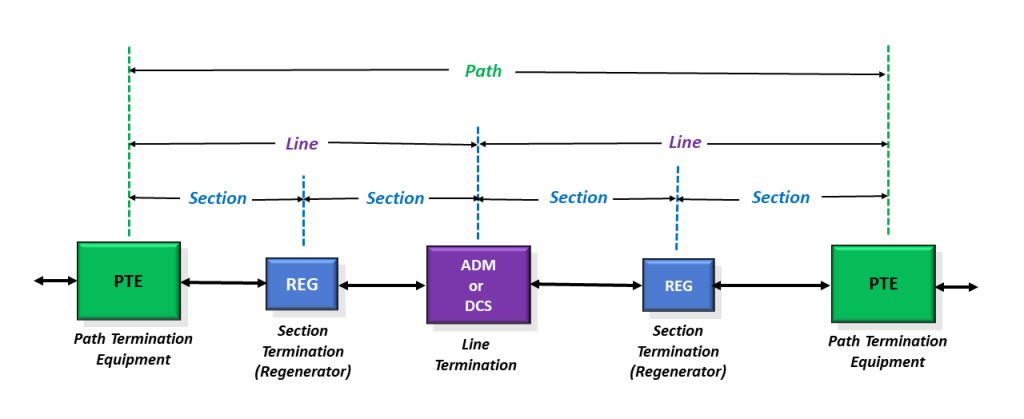
Figure 1, Illustration of the SONET Layers and Some Optical Equipment
We will now briefly describe some of these layers.
The Physical Layer
In SONET, the Physical Layer deals with the transport of bits across the transmission medium.
There are no overhead bytes associated with the Physical Layer.
The main function of this layer is in the conversion between an STS-N digital data stream and either external optical or electrical SONET signals.
Design issues associated with this layer typically include the following parameters:
- Pulse Shape
- Power Levels
- Line Code
- Timing
- Connectivity
NOTE: Optical Modules communicate at this layer.
The Section Layer
The Section Layer involves transporting an STS-N data stream across the physical medium (e.g., copper or optical fiber) in a point-to-point manner (e.g., between any two adjacent pieces of equipment).
This layer aims to ensure that the STS-N data stream, transported over a given link, coaxial cable, or optical fiber, is properly received.
Figure 2 presents a simple illustration of a Section.

Figure 2, Simple Illustration of a Section (a link between any two adjacent pieces of Equipment)
Functions within this layer include:
- Framing
- Scrambling
- Error detection
- Section-Level Communications Overhead, such as the local orderwire.
- Data Communication Channels (DCC) to carry information for OAM & P (Operation, Administration, Maintenance, and Performance).
What is Section Terminating Equipment (STE)
We refer to any piece of equipment that manages the transmission and reception of STS-N data over a single link of optical fiber or coaxial cable as an STE (Section Terminating Equipment).
An STE will manage the transmission and reception of STS-N data via the Section Overhead (SOH) bytes.
The SOH bytes reside in (and are a subset of) what we refer to as the “Transport Overhead” (TOH) bytes.
Figure 3 presents another look at the SONET Frame, with the TOH bytes field identified.

Figure 3, Another Look at the SONET Frame – TOH Bytes Highlighted.
I show (once again) that the TOH can be further divided into the SOH (Section Overhead) and Line Overhead (LOH) in Figure 4 below.
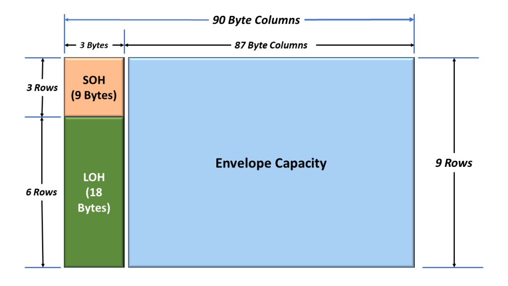
Figure 4 illustration the TOH being further divided into the SOH and LOH.
More about the SOH (Section Overhead Bytes)
As I mentioned earlier, we use the SOH (Section Overhead Bytes) to manage the transport of an STS-N signal across a Section.
Figure 5 presents a simple illustration of the 9 SOH bytes
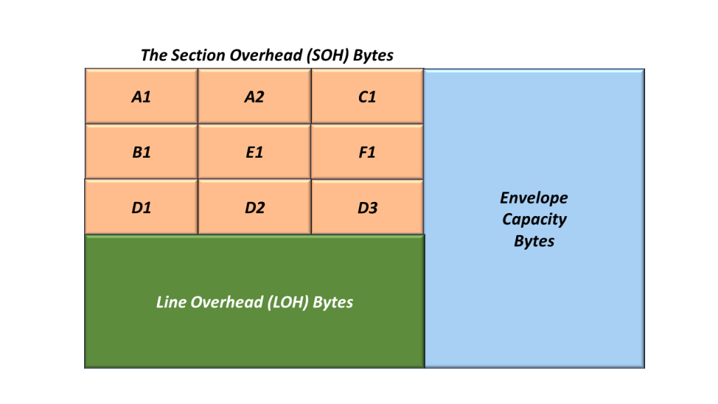
Figure 5, Illustration of the Nine (9) SOH bytes
We discuss the function/role of the SOH bytes in another blog post.
The Line Layer
The Line Layer is the second highest layer within the SONET Reference Model.
The purpose of the Line Layer is to support the transmission of data between the Source and Sink Terminal of a given STS-N signal.
The Line Layer is different from the Section Layer in that it (the Line Layer) will involve multiple pieces of electrical or optical transmission equipment. The Line Layer begins when we create a specific STS-N signal and ends when we terminate this STS-N signal.
The Section Layer only involves two adjacent pieces of electrical or optical transmission equipment.
Figure 6 presents an illustration of some STS-1 and STS-3 circuitry that helps to define the Line.

Figure 6, Definition of an STS-N Line (or STS-3 Line)
In Figure 6, we define a “Line” as the circuitry and communication media from the point where we multiplex three STS-1 signals into an STS-3 to the point where we terminate the STS-3 signal and de-multiplex them back into the 3 STS-1 signals.
What is Line Terminating Equipment (LTE)
Any piece of equipment that manages the transmission and reception of an STS-N data-stream, from the point that we create this (STS-N) signal to the point where we terminate this (STS-N) signal.
An LTE will manage the transmission and reception of STS-N data via the Line Overhead (LOH) bytes.
The LOH bytes reside in (and are a subset of) what we often refer to as the “Transport Overhead” (TOH) bytes.
All LTEs are also STEs.
Therefore, all LTEs will manage the transmission and reception of STS-N data via both the “SOH” and “LOH” bytes.
Figure 7 illustrates the LOH (Line Overhead) bytes within an STS-1 Frame.
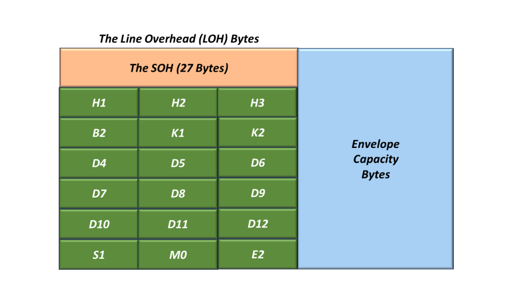
Figure 7, Illustration of the LOH (Line Overhead) Bytes within an STS-1 Frame.
We discuss the function/role of the LOH (Line Overhead) bytes in another blog post.
The Path Layer
The purpose of the Path Layer is to support and manage the transport of “non-SONET” client data from the point where we map this client signal into the SONET network to the point where it exits (or is de-mapped) from the SONET network.
Examples of non-SONET data being mapped into and transported via a SONET Network are DS1, E1, DS3, ATM, Ethernet, etc.
Each STS-N SPE consists of nine (9) Path Overhead bytes.
Figure 8 illustrates the Location of the Path Layer within our drawing of Optical Equipment.
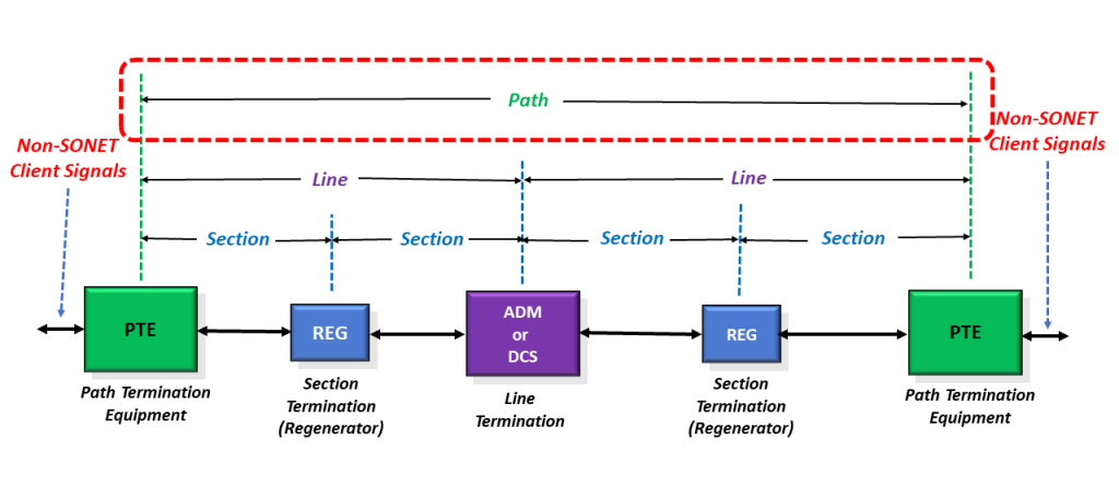
Figure 8, Location/Identification of the Path Layer, within our drawing of Optical Equipment
What is Path Terminating Equipment – PTE
Any piece of equipment that manages the transmission and reception of non-SONET data, or client signal, from the point that it enters the SONET network to the point that the SONET Network is terminated (and the client signal is de-mapped from the SONET signal) is referred to as a PTE (Path Terminating Equipment).
A PTE will manage the transmission and reception of non-SONET client data (through the SONET network) via the “Path Overhead” (POH) bytes.
The POH bytes reside within the first column in the SPE.
Figure 9 illustrates the Synchronous Payload Envelope (SPE) with the Path Overhead (POH) Bytes.

Figure 9, Illustration of the Synchronous Payload Envelope (SPE) with the Path Overhead (POH) Bytes.
NOTE: All PTEs are also LTEs and STEs.
Therefore, all PTEs will manage the transmission and reception of STS-N data via both the “SOH,” “LOH,” and “POH” bytes.
I discuss the function/role of the Path Overhead (POH) bytes in another blog post.
Where is the Synchronous Payload Envelope?
In each of the figures above (e.g., Figures 3, 4, 5, and 7), I do not refer to the Synchronous Payload Envelope (SPE). I only refer to the Envelope Capacity (within the SONET Frame). I discuss the relationship between the Envelope Capacity and the SPE in another blog post.
