
What is the Purpose of the Path Layer in the SONET Network?
The purpose of the Path Layer is to support and manage the transport of “non-SONET” client data from the point where it gets mapped into a SONET signal to the point where it exits (or is de-mapped) from that same SONET signal.
Examples of non-SONET data being mapped into and transported via a SONET Network are DS1, E1, DS3, ATM, Ethernet, etc.
Each STS-N SPE consists of nine (9) Path Overhead bytes.
Figure 1 illustrates the Location of the Path Layer within our drawing of Optical Equipment.
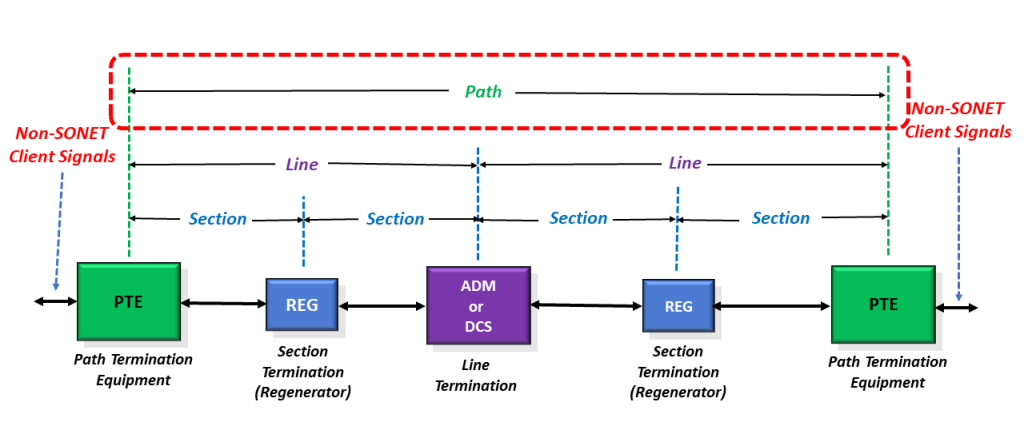
Figure 1, Location/Identification of the Path Layer, within our drawing of Optical Equipment
What is Path Terminating Equipment (PTE)?
Any piece of equipment that manages the transmission and reception of non-SONET data, or client signal, from the point that it enters the SONET network to the point that the SONET Network is terminated (and the client signal is de-mapped from the SONET signal) is referred to as a PTE (Path Terminating Equipment).
A PTE will manage the transmission and reception of non-SONET client data (through the SONET network) via the “Path Overhead” (POH) bytes.
NOTE: All PTEs are also LTEs and STEs.
Therefore, all PTEs will manage the transmission and reception of STS-N data via both the “SOH,” “TOH,” and “POH” bytes.
The POH bytes reside within the first column in the SPE (Synchronous Payload Envelope).
In Figure 2, I show a picture of an SPE with the POH Bytes included.
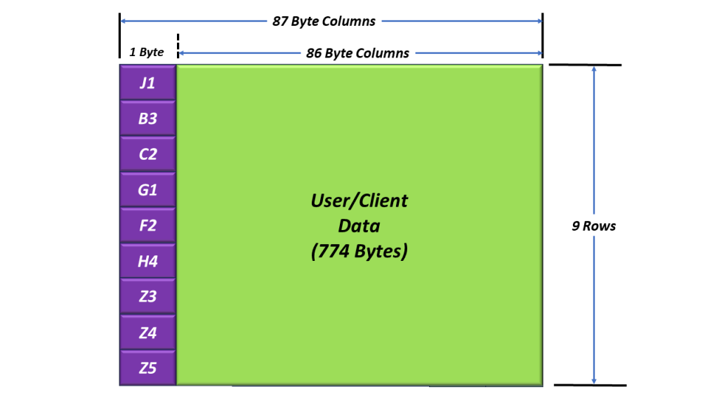
Figure 2, Illustration of an SPE with the POH Bytes
The Definition of the Path Overhead (POH) Bytes
We will briefly define each of the POH bytes (within an SPE) below.
The J1 – Path Trace Byte
In Figure 3, I show a picture of the STS-1 SPE and POH with the J1 byte highlighted.
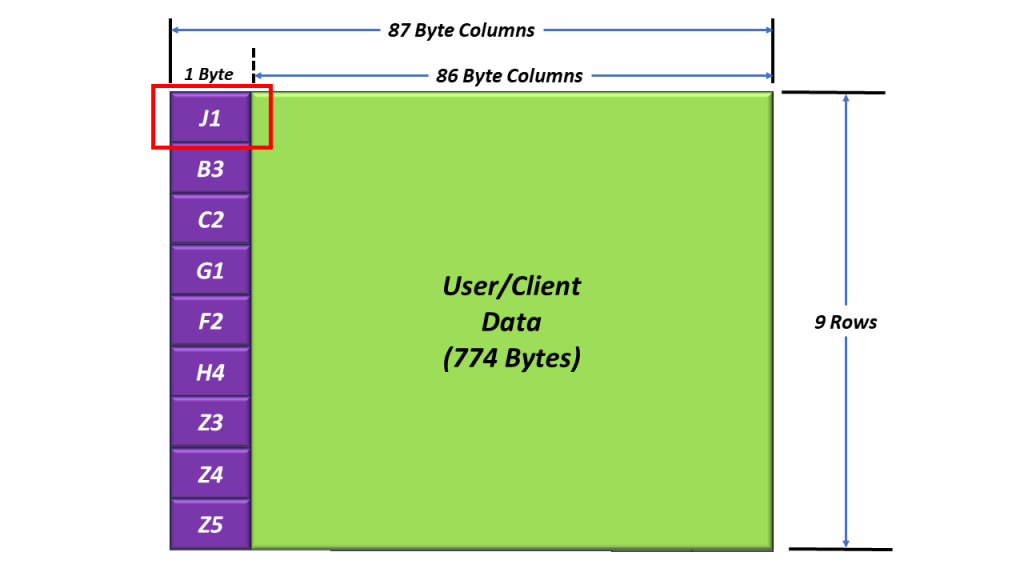
Figure 3, Illustration of the STS-1 SPE and POH bytes, with the J1 Byte Highlighted
The J1 byte is the very first byte within the SPE. This is also the byte that the H1 and H2 bytes (e.g., the Pointer Bytes) point to with an STS-N frame.
For SONET applications, this byte is used to transport a repetitive 64-byte message so that the receiving Path Terminal Equipment (PTE) can verify its continued connection to the intended transmitting STS-N PTE.
NOTE: For SDH applications, this byte can be used to transport a repetitive 16-byte message instead.
A given PTE will declare and clear the TIM-P (Path-Trace Identification Mismatch) defect condition.
The TIM-P defect is typically an indication of a cross-connecting or provisioning error.
I discuss the TIM-P defect condition in greater detail in another blog post.
B3 – Path BIP-8 Byte
Figure 4 presents the location of the B3 byte within the POH.

Figure 4, The Location of the B3 Byte within the POH.
The Role of the Transmit PTE (in Handling the B3 Byte)
A Transmitting PTE will compute the contents of the B3 byte by performing a BIP-8 calculation over all bits within the POH and the SPE (after scrambling).
This byte value is inserted into the B3 Byte field (within the very next outbound SPE) before scrambling the current STS-1 frame.
The Role of the Receive PTE (in Handling the B3 Byte)
- As a Receiving PTE receives its STS-1 SPE data stream, it will compute its own BIP-8 value.
- Afterward, the Receive PTE will compare its “locally” computed BIP-8 value with the value residing within the B3 byte field of the next STS-1 SPE.
- If the two values are the same, then the Receive PTE will “conclude” that it has received this STS-1 SPE data in an un-erred manner.
- If the two values are different, then the Receive PTE will “conclude” that it received this STS-1 SPE in an erred manner.
- We discuss how SONET PTE should flag the occurrence of B3 byte errors in another blog post.
NOTES:
- The B3 byte (in SONET) is analogous to the Path BIP within an ODU Frame.
- In another blog post, we will discuss how the Transmit PTE computes the B3 byte and how the Receive PTE Terminal verifies the B3 byte.
C2 – Path Signal Label Byte
Figure 5 presents the location of the C2 byte within the POH.

Figure 5, The Location of the C2 Byte within the POH.
The C2 (Payload Label) byte is used to indicate the content (or type of data) that is being carried within the SPE.
The C2 byte also includes the status of Mapped Payloads.
This byte can indicate the occurrence of defects within the data we are transporting via the SPE.
The C2 byte is analogous to the PSI (Payload Structure Identifier) Message that OPU frames transport in OTN.
I describe the roles of the C2 byte in greater detail in another blog post.
G1 – Path Status Byte
Figure 6 presents the location of the G1 byte within the POH.
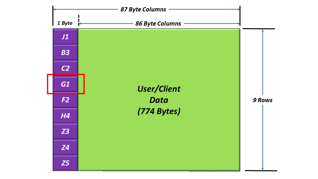
Figure 6, The Location of the G1 Byte within the POH.
We use the G1 byte to transport the following alarm/defect conditions throughout the SONET Network.
- REI-P (Path – Remote Error Indication)
- RDI-P (Path – Remote Defect Indication)
I discuss the role of the G1 byte and the transport of the REI-P and RDI-P alarm/defect conditions in another post.
H4 Byte – Mapping Indicator Byte
Figure 7 presents the location of the H4 byte within the POH.
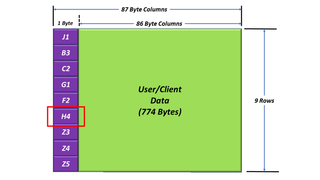
Figure 7, Location of the H4 Byte within the POH.
The H4 Bye is defined for use as a “mapping-specific indicator” byte. Currently, the only applications that use the H4 byte involve VT-mapping and virtual concatenation.
We discuss how we use the H4 byte in VT-Mapping and Virtual Concatenation applications in other blog posts.
Z3 Byte – Undefined (For Future Use)
Z4 Byte – Undefined (For Future Use)
Z5 (or N1) Byte – STS Tandem Connection Monitoring
Figure 8 presents the location of the Z5 (N1) byte within the POH.

Figure 8, The Location of the Z5 (or N1) Byte within the POH.
We use the Z5 (or N1) byte to support TCM (Tandem Connection Monitoring) in the SONET Network.
We discuss using the N1 byte for Tandem Connection Monitoring in the SONET Network in another blog post.