

What is an AIS (Alarm Indication Signal)?
What does the term AIS Mean?
AIS is an acronym for Alarm Indication Signal.
Where is the AIS Signal Used?
The AIS signal is a particular type of alarm (or maintenance) signal that a Network Element (within a Telecom/Datacom application) will generate and transmit (in its downstream path) anytime it detects some service-affecting defect upstream.
For example:
Suppose a Network Element (NE) was to declare the LOS (Loss of Signal) or the LOF (Loss of Frame) defect within its incoming telecom/datacom signal. In that case, it will respond to this defect condition by transmitting the AIS signal downstream.
Whenever the Network Element transmits this AIS signal downstream, it is (in effect) replacing its defective incoming signal with the AIS signal.
What EXACTLY is an AIS signal?
The exact pattern/signature of an AIS signal depends upon the telecom/datacom standard and network layer we use.
For some datacom/telecom standards, the AIS signal is transmitted (and received) as an Unframed All One’s pattern.
In other standards, we will transmit the AIS indicator as a Framed All One’s pattern (e.g., where the framing alignment fields still use typical values, but the payload fields are filled with an All One’s pattern).
Finally, the OTUk AIS pattern is an Unframed PN-11 (PRBS11) pattern.
In all cases, the NE will generate and transmit the AIS signal at the nominal line rate (of the customarily transmitted signal).
The frequency accuracy requirements for this AIS signal also depend on the governing standards for the Telecom/Datacom system.
I have included posts that define the AIS patterns for OTUk and ODUk types of signals (for OTN applications).
When do we transmit the AIS pattern?
We will go through a couple of examples to illustrate how and when we will transmit the AIS signal.
Example # 1 – The Unerred/Normal Condition
Figure 1 presents a straightforward illustration of a portion of a 3R Repeater/Regenerator, which consists of the following components:
- Two (2) Receive Line Interface blocks (one block is labeled W for West, and the other block is labeled E for East)
- Two (2) Receive Framer blocks (W – West and E – East)
- Two (2) Transmit Line Interface blocks (W – West and E – East)
- Two (2) Transmit Framer blocks (W – West and E – East)
- CS (Clock Smoothing/Jitter Attenuation) PLL (Phase-Locked Loop)
- AIS OSC (Stand-Alone Oscillator).
- FIFO/Buffer
- Two (2) Defect Decoder blocks (W – West and E – East)
In this figure, our 3R Repeater/Regenerator receives a good (error-free) signal from the “West Terminal.”
The 3R Repeater/Regenerator will first receive this signal through its Receive Line Interface (W) block.
Afterward, this signal passes through to the Receive Framer (W) block.
Suppose the Receive Line Interface (W) and the Receive Framer (W) blocks were to detect no problems within this signal. In that case, the 3R Repeater/Regenerator will allow this signal to pass through the Transmit Framer (E) and Transmit Line Interface (E) blocks as is.
Our 3R Repeater/Regenerator will transmit this same data to the East Terminal.
Additionally, the Transmit Framer (E) and Transmit Line Interface (E) blocks would transmit the outbound data (towards the East Terminal) based upon the Recovered Clock signal (which originated from the West Terminal and has been routed through the Clock Smoothing PLL for Jitter Attenuation purposes).
Figure 1 presents an illustration of this Normal (No Defect) Condition.

Figure 1, Illustration of the 3R Repeater/Regenerator – during Good/Normal Conditions.
Please note that I have grayed out the non-relevant portions of Figure 1 so we can focus our discussion on this Defect Declaration to AIS Generation mechanism in the West-to-East Terminal Path.
Now we will illustrate the case where we will transmit the AIS indicator.
Example # 2 – The dLOS/Abnormal Condition
Figure 2 presents another straightforward illustration of a 3R Repeater/Regenerator.
However, in this figure, there is an impairment in the signal that originates from the West Terminal such that our Network Element is now declaring the dLOS (Loss of Signal) defect with this signal.
It is possible that a backhoe or some other mishap severed this signal.
Nonetheless, our 3R Repeater/Regenerator is no longer receiving its signal from the West Terminal.
This also means that our 3R Repeater/Regenerator has no data to send to the East Terminal.
In this situation, our 3R Repeater/Regenerator will respond by doing the following things.
The Receive Line Interface (W) or the Receive Framer (W) blocks will declare the dLOS (Loss of Signal) defect with the signal that it is receiving from the West Terminal.
The Transmit Framer (E) and Transmit Line Interface (E) (which resides directly behind the Receiving Line Interface and Framer blocks – that are declaring the dLOS condition) will proceed to transmit the AIS indicator (to the East Terminal) as a replacement signal for the signal that we are no longer receiving from the West Terminal.
Additionally, the Transmit Framer (E) and Transmit Line Interface (E) blocks would transmit the AIS pattern (towards the East Terminal) based upon the output frequency of the AIS Oscillator (which is a stand-alone oscillator – that operates at the specified line-rate/clock frequency).
Figure 2 illustrates the dLOS/AIS Transmission Condition for our 3R Regenerator/Repeater.
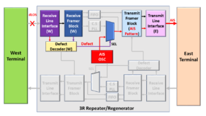
Figure 2, Illustration of the 3R Repeater/Regenerator – during the dLOS/Abnormal Condition.
The Transmit Framer (E) and Transmit Line Interface (E) blocks will continue to transmit the AIS indicator to the East Terminal for the duration that the Receive Line Interface (W) and the Receive Framer (W) blocks are declaring the dLOS defect with the signal that they are receiving from the West Terminal.
The Transmit Framer (E) and Transmit Line Interface (E) blocks will cease to transmit the AIS indicator once the Receive Line Interface (W) and the Receive Framer (W) blocks clear the dLOS defect and start to receive good/normal data from the West Terminal.
At this point, the Transmit Framer (E) and Transmit Line Interface (E) blocks will transmit good/normal data to the East Terminal.
In addition to the dLOS defect, the Network Element will typically transmit the AIS indicator (downstream) in response to the following other defects.
- dLOF (Loss of Frame Defect)
- dLOM (Loss of Multi-Frame Defect)
- dLOFLANE (Loss of Frame of Logical Lane) – for OTL3.4 or OTL4.4 applications (*)
- dLOL (Loss of Lane Alignment) – for OTL3.4 or OTL4.4 applications (*)
- dTIM (Trail Trace Identifier Mismatch)
(*) – Need to be a member of THE BEST DARN OTN TRAINING PRESENTATION…PERIOD!!! to access these links.
Why do we bother to transmit the AIS signal as a replacement signal?
We transmit the AIS indicator downstream in response to service-affecting defects for several reasons.
I will list some of those reasons below.
- Alerts downstream equipment that we have detected and declared a service-affect defect upstream.
- To suppress (or prevent) the downstream equipment from declaring their service-affecting defect.
- Aids in troubleshooting and system debugging. It is easier to isolate the causes of defect conditions if we know exactly which NE is declaring the defect and not the whole chain of NEs downstream.
- The downstream Receive Circuitry provides a much-needed clock signal at the correct bit rate. Clock Recovery PLLs (Phase-Locked-Loops) and Bias Controllers (for Optical Receive circuitry) all need upstream NEs to provide them with a line signal with the appropriate timing (bit-rate).
The AIS signal accomplishes these goals.
Has Inflation got You Down? Our Price Discounts Can Help You Fight Inflation and Help You Become an Expert on OTN!! Click on the Banner Below to Learn More!!!
Discount Available Temporarily
