

What is 1+1 Protection Switching?
ITU-T G.808 Defines 1+1 (Protection) Architecture as:
A 1+1 protection architecture has one normal traffic signal, one working transport entity, one protection transport entity, and a permanent bridge.
At the source end, the normal traffic signal is permanently bridged to both the working and the protection transport entities.
At the sink end, the normal traffic signal is selected from the better of the two transport entities.
Due to the permanent bridging, the 1+1 (protection) architecture does not allow an unprotected extra traffic signal to be provided.
What Does All This Mean?
As for all Protection Groups, a 1+1 Protection Architecture consists of the following elements.
- The Head-End (or Source-End)
- The Tail-End (or Sink-End)
- The Normal Traffic Signal
- The Working Transport entity
- The Protect Transport entity
- Protection Switching Controller (that can detect and declare defects within the Normal Traffic Signal).
- An APS Communications Link/Protocol (if needed)
Figure 1 presents an illustration of a 1+1 Protection Switching Architecture.
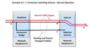
Figure 1, Illustration of a 1+1 Protection Switching Architecture – Normal (No Defect) Condition
How to Know if You’re Working with a 1+1 Protection Architecture?
This figure shows that a Permanent Bridge realizes the Head-End (of this Protection Group) and that a Selector Switch realizes the Tail-end. This is a crucial characteristic of the 1+1 Protection Architecture.
As we defined earlier (from the excerpts of ITU-T G.808), the Permanent Bridge means that there is a hardwired connection between the Normal Traffic Signal and both the Working and Protection Transport entities at the Head-End circuitry. This fact helps you to identify a 1+1 Protection Architecture quickly. This is not the case for a 1:N Protection Architecture.
You can see all of this in Figure 1.
No-Defect Operation of the Normal Traffic Signal in a 1+1 Protection Architecture
The Normal Traffic Signal will travel through the Working Transport entity for normal conditions, as shown in Figure 1.
Although the Normal Traffic signal is bridged (or connected) to both the Working and Protect Transport entities, it only flows through the Working Transport entity because we connected the Selector switch to the Working Transport entity.
Whereas the Selector Switch leaves the connection between the Protection Transport entity and the Tail-End circuitry, OPEN.
Clueless about OTN and Protection Switching? We Can Help!!! Click on the Banner Below to Learn More!!!
Corporate Discounts Available!!!

A Service-Affecting Defect occurs.
Now, let us look and see what happens if “bad things” occur.
Figure 2 presents an illustration in which an impairment now exists within the Working Transport entity; this impairment causes the Protection Controller (not shown but sitting behind the Tail-end circuitry) to declare a Service-Affecting defect (e.g., SF) or SD.

Figure 2, Illustration of a Service-Affecting Defect within the Working Transport entity
In this case, the Normal Traffic signal can no longer travel through the Working Transport entity.
If our circuitry did not have any protection switching capability, then all the customers (and end-users) of the Normal Traffic Signal would lose their service.
This would be very bad, especially for the service provider and their financial future.
Protection Switching Occurs
Fortunately, this system does offer protection switching.
In this case, since the Protection Controller has detected and declared a service-affecting defect condition within the Working Transport entity signal, it will then switch the Selector such that it is now connected to the Protect Transport entity, as we show in Figure 3.
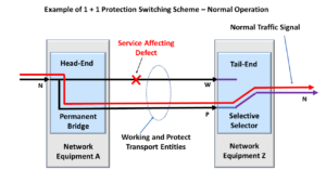
Figure 3, Illustration of Normal Traffic signal flow – following Protection Switching
Once the Selector switches over and connects to the Protection Transport entity, the Normal Traffic signal will flow through the Protection Transport entity.
This is an excellent thing for all parties involved.
The users (of the Normal Traffic signal) will get their data or have their service still available. And the service provider will have fewer irate customers and nasty phone calls.
Other Considerations for 1+1 Protection Switching
The 1+1 Protection Switching Architecture is quite simple.
We usually implement the head-end with a Permanent Bridge and realize the tail-end with a Selector switch.
However, there are some variations that we need to consider for the 1+1 Protection Switching architecture.
Unidirectional or Bidirectional Switching
The user can design their 1+1 Protection Switching architecture to be either a Unidirectional or Bidirectional type.
Please see the Unidirectional and Bidirectional Protection Switching posts for more details on these terms.
NOTE: If you intend to use Bidirectional Protection Switching, then you will need to use some form of APS communication link/protocol to coordinate the switching of both ends of the protection group.
Protection Ratio:
The protection ratio for a 1+1 Protection Switching system is not very good. This situation is not good because the user must design twice (2X) the bandwidth of the Normal Traffic signal.
We have to allocate 1X of the bandwidth for the Working Transport entity and 1X for the Protection Transport entity.
To Revert or Not-Revert
If a Protection Switching architecture supports “revert” (or reverting), then this means that the Selector switch will automatically switch back to the Working Transport entity once the service-affecting defect (which caused the switching event) has cleared.
Please see the post on revert for more details about this option.
Has Inflation got You Down? Our Price Discounts Can Help You Beat Inflation and Help You Become an Expert on OTN and Protection-Switching!! Click on the Banner Below to Learn More!!
Discounts Available for a Short Time!!
Click on the Image Below to see more Protection-Switching related content on this Blog:
