OTN – Lesson 12 – APS Features within Atomic Functions – Part 1

This blog post presents a video that discusses the APS features within some of the Atomic Functions that we discussed in Lessons 9 and 10.

Lesson 12 – Video 12 – Detailed Implementation of APS within the Atomic Functions – Video 1

This blog post starts our discussion of the APS Features within various Atomic Functions. In this case, we will present how to implement Automatic Protection Switching in great detail. In particular, we will describe the following:

  • APS Features within the OTUk/ODUk_A_So and OTUk/ODUk_A_Sk functions (OTU-Layer/SNC/I Monitoring)
    • How do we implement the APS features within these Atomic Functions to support OTU-Layered SNC/I Monitoring and Protection-Switching?
    • How do we implement a complete System-Level design (using these atomic functions along with the OTUk_TT_So and OTUk_TT_Sk Atomic Functions)?
      • NOTE: We discussed these atomic functions in Lesson 9. However, we did not discuss the APS features (within those functions) then.
  • APS Features within the ODUkP/ODUj-21_A_So and ODUkP/ODUj-21_A_Sk functions (ODU-Layer/SNC/I Monitoring)
    • How do we implement the APS features within these Atomic Functions to support ODU-Layered SNC/I Monitoring and Protection-Switching?
    • How do we implement a complete System-Level design (using these atomic functions along with the ODUk_TT_So and ODUk_TT_Sk Atomic Functions)?
      • NOTE: We discussed these atomic functions in Lesson 10. However, we did not discuss the APS features (within those functions) then.
  • APS Features of the ODUkP/ODUj-21_A_So and ODUkP/ODUj-21_A_Sk functions (CL-SNCG/I Monitoring)
  • How do we implement the APS features within these Atomic Functions to support CL-SNCG/I Monitoring and Protection-Switching?
  • How do we implement a complete System-Level design (using these atomic functions along with the ODUk_TT_So and ODUk_TT_Sk Atomic Functions)?
    • NOTE: We discussed these atomic functions in Lesson 10. However, we did not discuss the APS features (within those functions) then.

Check Out the Video Below

Continue reading “OTN – Lesson 12 – APS Features within Atomic Functions – Part 1”

OTN – Lesson 12 – Conclusion of Discussion of APS Commands for Protection Switching – Part IV

This blog post presents a video that concludes our discussion of APS Commands via the APS/PCC Communications Protocol

Lesson 12 – Video 11 – Detailed Discussion of APS Commands – Video 4

This blog post completes our discussion of APS Commands and the APS/PCC Communications Protocol. This video serves as Video 4 in this discussion. This blog post briefly discusses the SD, Manual Switch, Wait-to-Restore (WTR), Reverse-Request (RR), and Do-Not-Revert (DNR) APS Commands.

Additionally, this video defines and discusses the 1 Phase APS Communication, 2 Phase APS Communication and 3 Phase APS Communication Procedures.

Finally, this video will define APS Recovery Time. This video will also present the ITU-T G.873.1 APS Recovery Time Requirements.

More specifically, this video will cover the following topics:

Detailed Topics Discussed

  • APS Commands (Continued)
    • SD_W (Signal Degrade in the Working Transport Entity)
    • SD_P (Signal Degrade in the Protection Transport Entity)
    • WTR (Wait-to-Restore)
    • RR (Reverse Request)
    • DNR (Do Not Revert)
  • 1 Phase APS Communication
    • Advantages of 1 Phase
    • Disadvantages of 1 Phase
  • 2 Phase APS Communication
    • Advantages of 2 Phase
    • Disadvantages of 2 Phase
  • 3 Phase APS Communication
    • Advantages of 3 Phase
    • Disadvantages of 3 Phase
  • Definition of APS Recovery Time

Check Out the Video Below

Continue reading “OTN – Lesson 12 – Conclusion of Discussion of APS Commands for Protection Switching – Part IV”

OTN – Lesson 12 – Continuation of Discussion of APS Commands for Protection Switching – Part II

This blog post presents a video that continues our discussion of APS Commands via the APS/PCC Communication Protocol. This video serves as Part 2 of this discussion.

Lesson 12 – Video 9 – Detailed Discussion of APS Commands – Video 2

This blog post continues our discussion of APS Commands and the APS/PCC Communication Protocol. This video serves as Video 2 in this discussion. This blog discussed implementing the LoP (Lock Out of Protection) and Force Switch Commands using the APS/PCC Communication Protocol.

In particular, this video will discuss the following topics:

  • Executing the LoP (Lock Out of Protection Command) – for both the 1+1 and 1:N Protection Architectures
    • What does the LoP Command do to the Protection Group?
    • How do we Implement this Command?
    • How do we Terminate this Command (to resume Normal Operation)
  • Executing the Force Switch – Normal Traffic Signal to Protection (for the 1+1 Protection Architecture)
    • How does this command’s execution affect the Protection Group’s operation?
    • How do we Implement this Command?
    • Implementing the Force Switch – NULL Test Signal to Protection Command – to resume Normal Operation.
  • Executing the Force Switch – Normal Traffic Signal n to Protection (for the 1:N Protection Architecture)
    • How does this command’s execution affect the Protection Group’s operation?
    • How do we Implement this Command?
    • Implementing the Force Switch – Extra Traffic Signal to Protection Command – to resume Normal Operation.

To Learn More About the LoP (Lock Out of Protection) and Force Switch Commands, Check Out the Video Below.

Continue reading “OTN – Lesson 12 – Continuation of Discussion of APS Commands for Protection Switching – Part II”

What is the Byte-Format of the APS/PCC Field for Linear Protection Switching Applications within the OTN

This blog post briefly defines and describes the Nibble and Byte fields of the APS/PCC field, for Linear-Protection-Switching and OTN Applications.

Introduction to the APS/PCC Field

This blog post aims to define and describe the byte format of the APS/PCC field within the ODU Overhead whenever we support Linear Protection Switching applications within the OTN. ITU-T G.873.1 specifies the byte/nibble format of the APS/PCC field that we use within the OTN for Linear Protection Switching.

Whenever the System Designer needs to support the following:

  • Linear Protection Switching within the Optical Transport Network (defined within ITU-T G.709)
  • An APS Communication Protocol (because the user is either using the 1:N Protection Architecture or Bidirectional Switching

Then the user will need to use the APS/PCC (Automatic Protection Switching/Protection Control Communications) channel (and field) to support the APS protocol.

The APS/PCC field resides within the ODU Overhead, as I show below in Figure 1.

Location of APS/PCC field within the ODU Overhead

Figure 1, Location of the APS/PCC Field within the ODU Overhead of an OTU Frame.

Figure 1 shows that the APS/PCC field resides within the fourth row and the fifth through eighth-byte position within an OTU frame. The length of the APS/PCC field is four bytes wide.

Whenever we are designing OTN networks to also support protection switching (and using the APS Communications Protocol) in the process, then we will use the APS/PCC field to transport APS Messages from one Network Element to another.

Byte/Nibble Format of the APS/PCC Field

I show the Byte/Nibble format of the APS/PCC field below in Figure 2.

APS/PCC Field Format for Linear Protection Switching Applications

Figure 2, Byte/Nibble format of the APS/PCC Field

Figure 2 shows that the APS/PCC field consists of the following Nibbles and Byte-fields:

Request/State Nibble (Bits 1-4)

The purpose of this Nibble-field is to either:

  • Transmit Protection-Switching commands or requests to the remote terminal of the Protection-Group, or
  • Transmit information about Defect Conditions or States.

Table 1 presents a list of values (within the Request/State Nibble field) and their corresponding Meaning.

Table 1, Standard Values within the Request/State Nibble field and their Corresponding Meaning.

Meaning of Request State Nibble field of APS/PCC Field - Linear Protection Applications

So, for example, if a given Protection Switching terminal needs to transmit the SF Command, it would set the Request/State Nibble (within its outbound APS Message) to [1, 1, 0, 0], as I show in Table 1.

Protection Type Nibble (Bits 5 – 8)

The Protection Type Nibble field occupies the second set of four bits of the APS/PCC field.

The purpose of this nibble-field is to communicate (to the remote end of the Protection Group) many of the governing parameters of our Protection-Switching scheme.

The following table presents a list of the bit-fields within the Protection-Type Nibble and their meaning/description.

Table 2, A List of the Bit-Fields, within the Protection-Type Nibble and their Meaning/Description

Protection Type Nibble of APS/PCC field
Bit A – APS Channel

This bit-field indicates if the Protection Group is either supporting an APS Communication Protocol or not, as I describe below.

  • 0 = No APS Channel (Not using the APS Communication Protocol)
  • 1 = APS Channel (We are using the APS Communication Protocol)
Bit B – Bridge (Permanent)

This bit-field indicates if the Protection Group supports the 1+1 or 1:N Protection Architecture, as I show below.

Bit D – Directional Switching

This bit-field indicates if the Protection Group supports Unidirectional or Bidirectional Switching, as shown below.

  • 0 = Unidirectional Switching
  • 1 = Bidirectional Switching
Bit R – Revertive Operation

This bit-field indicates if the Protection Group supports the Revertive or Non-Revertive Operation, as I show below.

  • 0 = Non-Revertive Operation
  • 1 = Revertive Operation

Requested Signal Byte – APS/PCC Field – Byte 2

The Requested Signal byte-field identifies the signal that the Near-End (e.g., the Requesting Terminal) requests to be carried over to the Protection Transport Entity.

Ultimately, we a request at the Far-End Terminal to place the Requested Signal on the Protection Transport Entity, following this Protection Command.

For the 1+1 Protection Architecture

For the 1+1 Protection Architecture, the Protection-Switching Terminal should set this byte-field to “0x01” (for most APS Commands) to denote Normal Traffic Signal # 1. Normal Traffic Signal # 1 is typically the ONLY Normal Traffic Signal in a given direction for a 1+1 Protection Switching Architecture.

For the 1:N Protection Architecture

If the Requesting Terminal wishes to command the remote end to bridge the NULL Test Signal to the Protection Transport entity, it should set this byte-field to 0x00 when issuing an APS command.

Likewise, suppose the Requesting Terminal wishes to command the remote end to bridge the Extra Traffic Signal to the Protection Transport entity. In that case, it should set this byte-field to 0xFF when issuing an APS command.

Finally, suppose the Requesting Terminal wishes to command the remote end to bridge a Normal Traffic Signal to the Protection Transport entity. During a Protection Switching event, it should set this byte-field to the appropriate number (corresponding with the defective Normal Traffic Signal). Valid Numbers for the Requested Byte value range from 0x01 to 0xFE, depending upon which Normal Traffic signal requires Protection-Switching.

Table 2 lists the appropriate Requested Signal Values for the 1:N Protection Architecture.

Table 2, List of Appropriate Requested Signal Values for the 1:N Protection Architecture

Requested Signal Byte Meaning - APS/PCC Field

Bridged Signal Byte – APS/PCC Field – Byte 3

For this field, the REQUESTING terminal will set this byte-field to the value that identifies which signal this terminal is currently bridging to the Protection Transport entity.

For the 1+1 Protection Architecture


When using the 1+1 Protection Architecture, the Protection-Switching Terminal should set this byte-field to “0x01” (for most APS Commands) to denote Normal Traffic Signal # 1. Normal Traffic Signal # 1 is typically the ONLY Normal Traffic Signal in a given direction for a 1+1 Protection Switching Architecture.

For the 1:N Protection Architecture

If the Requesting Terminal is bridging the NULL Test Signal to the Protection Transport entity, it must set this byte-field to 0x00 when issuing an APS command. The Requesting Terminal tells the remote terminal that it is bridging the NULL Test Signal to the Protection Transport entity.

Likewise, if the Requesting Terminal is bridging the Extra Traffic Signal to the Protection Transport entity, it must set this byte-field to 0xFF when issuing an APS command.

Finally, suppose the Requesting Terminal is currently implementing Protection Switching and is bridging one of the Normal Traffic Signals to the Protection Transport entity. In that case, it must identify that Normal Traffic Signal by setting this byte-field to the appropriate number (corresponding with the defective Normal Traffic Signal). Valid Numbers for the Requested Byte value range from 0x01 to 0xFE, depending upon which Normal Traffic signal requires Protection-Switching.

Table 3 presents a list of the appropriate Bridged Signal Values for the 1:N Protection Architecture.

Table 3, List of Appropriate Bridged Signal Values for the 1:N Protection Architecture

Bridged Signal Byte Meaning - APS/PCC Field

Reserved Byte – Byte 4

This byte-field is reserved for future use/standardization.

Clueless About OTN? We Can Help!! Click Below to Learn More!!

Example of Using the APS/PCC Field for the 1+1 Protection Architecture

Let’s suppose we use the 1+1 Protection Architecture within our Protection Scheme. Further, let’s assume that one of the Network Elements declares the SF_W (Signal Fail within the Working Transport Entity) condition, as shown below in Figure 3.

SF Declared in Normal Traffic Signal # 2 - 1+1 Protection Architecture

Figure 3, Tail-End Circuit at NE Z declares the SF_W Condition.

NE Z Sends the SF_W APS Message to NE A

In this case, NE Z (the Network Element declaring the SF_W Condition) will need to send the SF_W APS Command to the remote terminal. I show this APS Command below in Figure 4.

NE Z sends SF_W APS Command to NE A - 1+1 Protection Architecture

Figure 4, NE Z sending the SF_W APS Command to NE Z.

Please note that (within this APS Command) NE Z is setting the Request Command to [1, 1, 0, 0] to denote that it is transmitting the SF Command.

Further, NE Z is also setting the Protection Type Nibble to information NE A, which is operating with the following Protection-Switching characteristics:

  • A = 1: We are using an APS Communication Protocol
  • B = 0: We are using a Permanent Bridge (for a 1+1 Protection Architecture)
  • D = 1: We are supporting Bidirectional Switching, and
  • R = 1: We are supporting Revertive Switching

Next, NE Z is setting the Requested Byte to “0x01”. This setting denotes two things:

  • First, we are declaring the SF condition within the Working Transport Entity. If we set the Requested Byte to “0x00”, this would denote that we are declaring the SF condition with the Protection Transport entity.
  • Second, we are requesting that the remote terminal (NE A, within Figure 4) should bridge the Normal Traffic Signal (Signal # 0x01) to the Protection Transport entity. (NOTE: Because this is the 1+1 Protection Architecture, we are already permanently bridging the Normal Traffic Signal (0x01) to the Protection Transport entity.

Finally, NE Z is setting the Bridged Byte to “0x01”. This setting denotes that we are already bridging the Normal Traffic Signal (0x01) to the Protection Transport Entity. The Permanent Bridge is inherent to the 1+1 Protection Architecture.

Subsequent APS Commands

NE A and NE Z will exchange more APS Commands to deal with this instance of the SF condition. I’m only showing the initial request from NE Z to NE A.

Example of Using the APS/PCC Field for the 1:N Protection Architecture

Let’s suppose we are using the 1:N Protection Architecture within our Protection Scheme. Further, let’s assume that one of the Network Elements declares the SF_W Condition with Working Transport Entity # 2, as I show below in Figure 5.

SF Declared in Normal Traffic Signal # 2 - 1:N Protection Architecture

Figure 5, Tail-End Circuit at NE Z declares the SF_W Condition for Working Transport Entity # 2.

NE Z Send the SF (within Normal Traffic Signal # 2) Message to NE A

In this case, NE Z (the Network Element declaring the SF_W Condition) will need to send the SF_W APS Command to the remote terminal. I show this APS Command below in Figure 6.

NE Z sends SF_W APS Command to NE A - 1:N Protection Architecture

Figure 6, NE Z sending the SF_W APS Command to NE Z.

Please note (again) that (within this APS Command) NE Z is setting the Request Command to [1, 1, 0, 0] to denote that it is transmitting the SF Command.

Further, NE Z is also setting the Protection Type Nibble to information NE A, which is operating with the following Protection-Switching characteristics:

  • A = 1: We are using an APS Communication Protocol
  • B = 1: We are using a Non-Permanent Bridge (for a 1:N Protection Architecture)
  • D = 1: We are supporting Bidirectional Switching, and
  • R = 1: We are supporting Revertive Switching

Next, NE Z is setting the Requested Byte to “0x02”. This setting denotes two things:

  • First, we are declaring the SF condition within the Working Transport Entity. If we set the Requested Byte to “0x00”, this would denote that we are declaring the SF condition with the Protection Transport entity.
  • Second, we are requesting that the remote terminal (NE A, within Figure 5) should bridge the Normal Traffic Signal # 2 (Signal # 0x02) to the Protection Transport entity. We are declaring the defect with Working Transport Entity # 2. We need to alert the remote terminal that we need to bypass this signal path.

Finally, NE Z is setting the Bridged Byte to “0x02”. This setting denotes that we are already bridging the Normal Traffic Signal # 2 (0x02) to the Protection Transport Entity.

Subsequent APS Commands

NE A and NE Z will exchange more APS Commands to deal with this instance of the SF condition. I’m only showing the initial request from NE Z to NE A.

More Information/Training

If you wish for more information/training on this topic, then check out the video on the APS Communication Protocol (*).

(*) – Requires membership to access.

Has Inflation got You Down? Our Price Discounts Can Help You Fight Inflation and Help You Become an Expert in OTN!! Click on the Banner Below for More Details!!

Click on the Image Below to see more Protection-Switching related content on this Blog:

Protection-Switching Related Blog

Protection-Switching Related Blog Posts

Protection-Switching Related Blog Posts Basic Protection-Switching Terms Head-End (Source Node) Hold-Off Timer Protection-Group Protection-Transport entity Selector Switch Tail-End (Sink Node) ...

ODU/ODUk – Optical Data Unit

This post defines and describes the ODU (Optical Data Unit) Frame that is used in OTN (Optical Transport Networks).

What is the ODU/ODUk (Optical Data Unit)?

An ODU (Optical Data Unit) is a data structure that Path Terminating Equipment (PTE)  within an Optical Transport Network (OTN) will generate and monitor as it transmits and receives data.

This post will call any entity that generates and transmits ODUk frames a Source PTE.  Likewise, we will call any entity that receives, processes, and terminates ODUk frames a Sink PTE.  

Anytime an OTN Terminal “wishes” to transport an ODUk frame to the outside world (over a fiber-optic connection), it will first encapsulate this data into an OTUk Frame.

In other words, an ODUk frame is a subset of an OTUk frame.

NOTE:  This post will discuss the ODUk structures (such as the ODU0, ODU1, ODU2, ODU2e, ODU3, ODU4, and ODUflex).

This post will not be discussing the new (higher-rate) ODUCn structures.  Please see the post on ODUCn structures for information on these types of structures.

OTN Path and Section Terminating Equipment

In the OTN arena, we will often state that the OTN Path Terminating Equipment (PTE) is the entity that is responsible for handling and processing ODUk frames.

We will also state that OTN Section Terminating Equipment (STE) handles and processes OTUk frames.

Please see the posts for OTN Path Terminating Equipment (PTE) and OTN Section Terminating Equipment (STE) to understand these two types of equipment.

The ODUk Frame Format

An ODUk consists of an OPUk structure, along with the ODUk Overhead fields.

Figure 1 presents an illustration of the ODUk structure, along with its overhead.

ODU Frame with ODU Overhead Shown

Figure 1, Illustration of an ODUk Structure

The ODU Structure (and Overhead) aims to help the OTN manage the transmission of OPU frames (transporting client data) from the Source PTE to the Sink PTE.

The OTN will use the ODU Overhead to monitor the Network’s performance and health (or the Path) as we transport these OPUk frames from the Source PTE to the Sink PTE.  

Figure 2 illustrates a single OTN Path network connection bounded by a Source PTE and a Sink PTE.

OTN Path Terminating Equipment connected to the Optical Transport Network

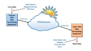
Figure 2, an Illustration of a single OTN Path (which is bounded by both a Source PTE and a Sink PTE)

The Source and Sink PTE (in Figure 2) will perform the following tasks on the data it processes.

Processing at the Source PTE

The Source PTE is a piece of equipment that will take on the responsibility of mapping a client signal into an OTN signal (e.g., into an OPUk structure).

Whenever the Source PTE maps this client signal (which could be a 1GbE, 100GbE, OC-48, FC-800 Signal, etc.) into an OTN signal:

  • It will accept the client data (from the client-side equipment), and it will map this signal into an OPUk Structure, and
  • The Source PTE will also compute and generate the ODUk Overhead, and
  • Finally, it will combine the ODUK Overhead and OPUk Structure to form an ODUk Frame.

Processing at the Sink PTE

The Sink PTE  will also be responsible for de-mapping (or extracting) the client signal from the OTN signal.

In this case, whenever the Sink PTE de-maps this client signal from an OTN signal:

  • It will evaluate the ODUk Overhead of each ODUk frame it receives (to check for client signal data integrity and the occurrence of defect conditions).  It will terminate the ODUk signal.
  • The Sink PTE will also terminate the OPUk structure and
  • It will de-map (or extract) the client signal from the OPUk structure.
  • Finally, the Sink PTE will output this client signal to the client-side equipment for further processing.

NOTE:  The OTN Path Terminating Equipment (at the “Source” and “Sink” terminals) will map (the client signal into an OTN signal) and de-map (the client from the OTN signal) in such a way as to minimize the amount of jitter within the de-mapped client signal.

Please see the posts on BMP, AMP, and GMP mapping for more details on this topic.

Things that the user can do with an ODUk frame

Once a “Source” PTE creates an ODUk frame, there are two things that it can do with the ODUk frames.

  • The Source PTE/STE can encapsulate this ODUk into an OTUk frame structure and then transmit this OTUk frame to a remote piece of terminal equipment (over a fiber-optic connection), or
  • It can treat this ODUk signal as a tributary signal and multiplex this ODUk signal into a higher-speed ODUm server signal (where m > k).  Please see the post on ODUk Multiplexing for more details.

You cannot transport an ODUk signal over optical fiber without first mapping this signal into an OTUk signal.  We only transport OTUk signals on optical fiber.  

Definition of the ODUk Overhead

The ODUk Overhead is a 3 Row by 14 Byte Column structure that contains the following thirteen (13) fields.

  • RES – Reserved
  • PM/TCM Byte
  • EXP – Experimental Byte
  • TCM1 Field
  • TCM2 Field
  • TCM3 Field
  • TCM4 Field
  • TCM5 Field
  • TCM6 Field
  • PM Field
  • GCC1 Field
  • GCC2 Field
  • APS/PCC Field

I describe each of these overhead fields below.

RES – Reserved

These fields are “reserved” and currently have no standardized role or function within the ODU overhead.

New Comprehensive OTN Training…Available Now. Click on the Banner Below to Learn More!!

Discounts Available for a Short Time!!

PM (Path Monitoring) Field (3 Bytes)

Figure 3 shows the byte format for the Path Monitoring Field.

ODU PM (Path Monitoring) Field

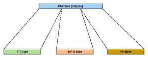
Figure 3, Byte-Format of the PM (Path Monitoring) Field.

Hence, Figure 3 shows that the PM Field consists of the following three bytes:

  • TTI- Trail Trace Identifier Byte
  • BIP-8 Byte
  • PM Byte

Below, we will describe each of the bytes (within the PM field).  We also discuss these bytes in much greater detail in other posts.

TTI Byte – Trail Trace Identifier Byte

This byte-field carries the 64-byte Path Monitoring Trail-Trace Identifier message.

Since there is only one TTI byte within each ODU frame (not including that within the TCMn fields), the Source PTE will have to transmit 64 consecutive ODUk frames to transmit this 64-byte Trail Trace Identifier message completely.

Please see the Path Monitor – Trail Trace Identifier post to see how we use this identifier in an OTN system.

BIP-8 (Path Monitoring, BIP-8) Byte

The PTE will perform a BIP-8 calculation over the entire OPUk frame within its corresponding ODUk frame.

Afterward, the Source PTE will insert the results of this BIP-8 calculation into the BIP-8 byte field of the outbound ODUk frame two frame periods later.

The remote Sink PTE will use this BIP-8 calculation to check for bit errors during transmission from the Source PTE to the Sink PTE.

Please see the Path Monitoring BIP-8 post for more information about this byte field and how it is computed and used in an OTN system.

PM (Path Monitoring) Byte

Figure 4 presents the bit format for the Path Monitoring byte (not to be confused with the 3-byte PM Field).

ODU PM (Path Monitoring) Byte - BEI, BDI, STAT

Figure 4, Bit Format of the Path Monitoring Byte

This figure shows that the PM Byte consists of the following bit-fields

  • BEI (4-bits)
  • BDI (1 bit)
  • STAT (3 bits)

We will briefly describe each of these bit-fields below.

BEI – Path Monitoring – Backward Error Indicator (BEI) (4 bits)

The purpose of the BEI Nibble field is to permit a Network Element (consisting of a Source PTE and a Near-End Sink PTE) to send feedback to the far-end Network Element on the quality of the ODUk signal that it is sending to our Network Element.

As the Near-End Sink PTE receives its stream of ODUk frames (from the far-end Network Element), it will check and verify the PM-BIP-8 values within each incoming ODUk frame.  

While the Near-End Sink PTE performs this task, it will determine the total number of bits in error between its locally computed PM-BIP-8 byte value and that it has received from the far-end Network Element.  

The Source PTE will obtain that number from its Near-End Sink PTE and then load that number (of PM-BIP-8 bits in error) into the BEI Nibble-field within the ODUk frames and transmits it back out to the far-end Network Element.  

In doing this, our local Network Element provides the far-end Network Element with the total number of PM-BIP-8 bit errors that are received from it.

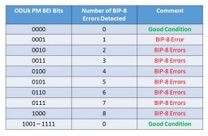
Table 1 lists the value that our Near-End Source PTE will set the BEI Nibble based upon the number of PM-BIP-8 bit errors that its Near-End Sink PTE has detected.  

Table 1, How to Interpret the Path Monitoring BEI bit-fields

ODUk PM BEI Bits and the Number of BIP-8 Errors Detected

Please see the Path Monitoring Error/Defect post to learn more about these defects and error conditions.

BDI – Path Monitoring – Backward Defect Indicator

The purpose of the BDI bit-field is to permit the Source PTE to alert the remote (far-end) Network Element that the local (near-end) Sink PTE is declaring a service-affecting defect.  

The Source PTE will set this bit-field to a “0” or “1” depending upon whether the local (near-end) Sink PTE is declaring a service-affecting defect condition (at the ODUk-layer), as I describe below. 

0 – The Source PTE will set the BDI bit-field to “0” if the near-end Sink PTE is NOT declaring a service-affecting defect condition.

1 – The Source PTE will set this bit-field to “1” if the near-end Sink PTE is currently declaring a service-affecting defect condition.

Please see the Path Monitoring Error/Defect post to learn more about the BDI defect.

STAT – ODU Path Monitoring Status (STAT) Indicator

The Sink PTE will use the STAT fields to determine if it should declare a Maintenance signal-related defect, as shown below in Table 2.

Table 2, How to Interpret the STAT bit-fields within the PM Field

STAT Field within the Path Monitor Field of an ODU Frame

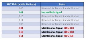
For example, if the Sink PTE were to receive (and accept) a STAT field value of [1, 0, 1], then the Sink PTE will declare the dAIS (ODUk-AIS) defect condition.  

PM/TCM Byte

For ODUk applications (e.g., ODU0, ODU1, ODU2, ODU3, ODU4, and ODUflex), the PM/TCM byte contains seven (7) defined bit-fields.

Figure 5 presents an illustration of the PM/TCM Byte-field.

Path Montoring/Tandem Connection Monitor Byte

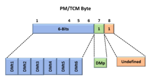
Figure 5, Illustration of the PM/TCM Byte-Field

This figure shows that Bit 7 (within the PM/TCM Byte-Field) functions as DMp (or Path Delay Measurement) and that bits 1 through 6 functions as DMti (of Tandem Connection Monitoring Delay Measurements).

Please see the DMp (Path Delay Measurement) post for more details on the DMp bit-field.  And please see the post on DMt1 through DMt6 (TCM Delay Measurements) for more information about the DMti bit-fields.

EXP – Experimental Byte (4 Bytes within the ODUk Overhead)

The ODU Overhead has a total of 4-byte fields that are labeled EXP.  There are two (2) 1-byte fields and one (1) 2-byte field for EXP.

There is no standard-specified use for the EXP bytes.

For now, the System Designer/Manufacturer can use these byte fields to support vendor-proprietary features if they choose to do so.

New Comprehensive OTN Training…Available Now. Click on the Banner Below to Learn More!!

Discounts Available for a Short Time!!

TCM1 (Tandem-Connection Monitoring 1) Field

TCM1 through TCM6 all support Tandem Connection Monitoring.

Please see the post on Tandem Connection Monitoring for more information on how these fields are used in the OTN.

The byte field for the TCM1 field is presented and briefly defined below.  See Figure 6 for the byte format of the TCM1 field.

TCMi (Tandem Connection Monitoring) Field

Figure 6, Byte-Format of the TCM1 Field

Figure 6 shows that the TCM1 Field consists of the following three bytes:

  • TTI- Trail Trace Identifier Byte
  • BIP-8 Byte
  • TCMi-SM Byte

NOTES

  1. The role of the TTI and BIP-8 bytes within the TCM1 field is identical to that presented for the ODUk Path Monitoring Field, and we will not repeat that discussion here.  Please see the post on Tandem Connection Monitoring for more details on how the OTN network uses these byte fields.
  2. Note that the TCMi-SM byte is different from the ODUk PM byte.  Please see the post on the TCMi-SM byte for more information on how we use this byte-field in the network.
  3. The role of the bytes within the TCM1 field is identical to that for the TCM2 through TCM6 fields, and we will not repeat that discussion below.  Please see the post on Tandem Connection Monitoring for more details on how the OTN network uses these byte fields.

TCM2 Field

Please see the description for the TCM1 Field.

TCM3 Field

Same as the description for the TCM1 Field.

TCM4 Field 

Please see the description for the TCM1 Field.

TCM5 Field

Same as the description for the TCM1 Field.

TCM6 Field

Please see the description for the TCM1 Field.

GCC1 – General Communication Channel # 1 – (2 byte)

The GCC1 field is a general communications channel for proprietary communication to the System Designer/Manufacturer.

This channel is similar to the DCC (Data Communication Channels) in SONET/SDH.

Please see the GCC1 post for more information about this field.

GCC2 Field – General Communication Channel # 2 – (2 Byte)

The GCC2 is a general communications channel for proprietary communication to the System Designer/Manufacturer.

This channel is similar to the DCC (Data Communication Channels) in SONET/SDH.

Please see the GCC2 post for more information about this field.

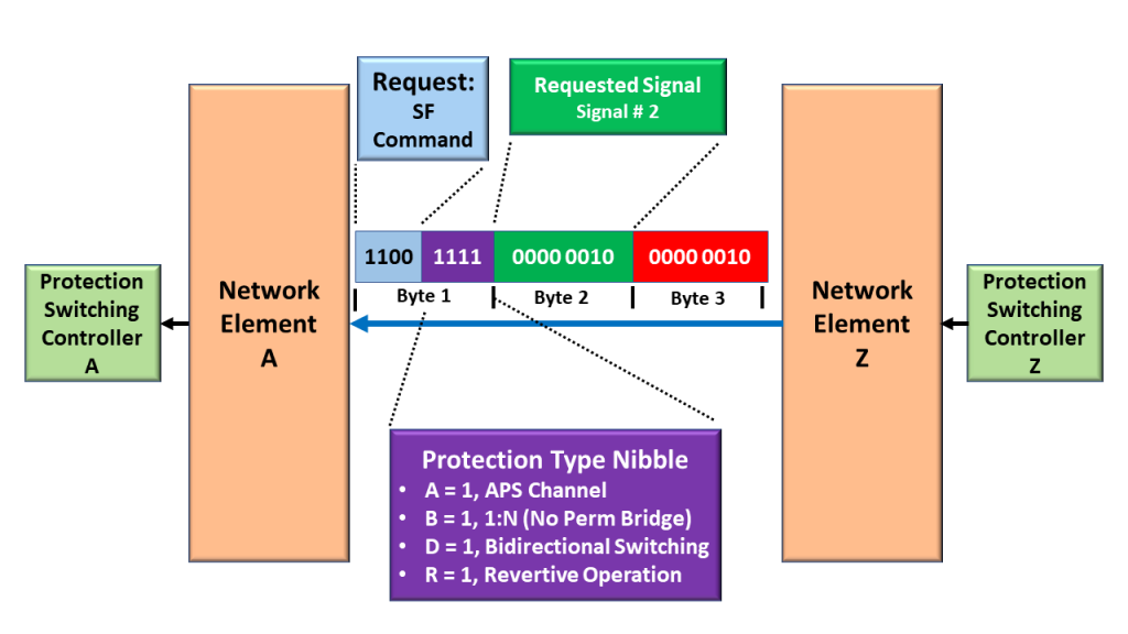
APS/PCC Field – ODU Automatic Protection Switching and Protection Communication Channel

Please see the ODU Automatic Protection Switching and the Protection Communications Channel post to learn more about how we use this 4-byte field in an OTN system.

ODUk Bit Rates

Table 3 presents the ODUk bit rate for each type of ODUk signal.

Table 3, Bit-Rate for each type of ODUk Signal

ODUk Bit Rate

NOTES:

  1. We define the ODUflex structure in another post.
  2. This post only addresses ODUk types of structures.  Please see the post on ODUCn to learn more about those structures.

Has Inflation got You Down? Our Price Discounts Can Help You Fight Inflation and Help You Become an Expert on OTN!! Click on the Banner Below to Learn More!!!

Discounts Available Temporarily

For More Information on OTN Posts in this Blog, click on the Image below.

OTN Related Blog

OTN Related Topics within this Blog

OTN Related Topics within this Blog General Topics Consequent Equations - What are they and How can you use them? ...