OTN – Lesson 9 – Video 11 – OTU Layer Defect Handling Requirements and Scenarios

In this video, we presume that some OTUk-Layer circuitry is declaring a certain defect condition. We then determine how OTU (and in some cases) ODU-layer circuitry is expected to respond.

OTN – Lesson 9 – Video 11 – OTU Layer Defect Scenarios

This blog post presents a video that discusses the various defects that OTN equipment can declare at the OTU Layer.  Additionally, this video will describe how OTU Layer circuitry should respond to and handle these defect conditions.  

This video will state whether OTU Layer circuitry should:

  • Transmit the SM-BDI Indicator upstream, or 
  • Transmit the ODU-AIS Maintenance Signal downstream, 
  • Increment Certain Performance Monitoring parameters, or
  • Halt Incrementing Certain Performance Monitoring parameters.

In response to each type of defect that OTU Layer circuitry can declare.

This video covers both Single-Lane (e.g., OTSi/OTUk_A_Sk) and Multi-Lane (e.g., OTSiG/OTUk_A_Sk) applications. 

Continue reading “OTN – Lesson 9 – Video 11 – OTU Layer Defect Handling Requirements and Scenarios”

OTN – Lesson 9 – Video 7 – OTUk_TT_Sk Function

This post presents the 7th of the 11 Videos that covers training on Performance Monitoring at the OTUk Layer. This post focuses on the Sink Direction OTU-Layer Atomic Functions.

OTN – Lesson 9 – Video 7 – OTU Layer Sink Direction Circuitry/Functionality – Part 5

This blog post contains a video that starts our discussion of the OTUk_TT_Sk Atomic Function.  

This blog post contains the 5th video that discusses the Sink (or Receive) Direction Atomic Functions at the OTU Layer.  This video is also the 7th of the 11 videos for Lesson 9.  

This video focuses on the following:

  • What is the CI_SSF input pin?
  • Near-End Error Checking  – SM-BIP-8 Verification
  • Sending SM-BEI Information based upon SM-BIP-8 Verification results.  
  • Far-End Error Checking – SM-BEI Monitoring
  • What does it mean to declare or clear the SM-BDI (or dBDI – Backward Defect Indicator) defect condition.  

Continue reading “OTN – Lesson 9 – Video 7 – OTUk_TT_Sk Function”

What is pF_DS at the OTUk Layer?

This blog post briefly defines the pF_DS (Far-End Defect Second) Performance Monitoring parameter – for the OTUk Layer.

What is the pF_DS (Far-End Defect Second) Performance-Monitoring Parameter for the OTUk Layer?

This blog post aims to briefly define and describe the pF_DS (Far-End Defect Second) Performance Monitoring parameter that the OTN STE (or OTUk_TT_Sk Atomic Function) will compute and generate.  

The OTN STE (or OTUk_TT_Sk function) will include information on pF_DS within each Performance Monitoring report it sends to System Management.  

Performance Monitoring - Another Image

NOTES:

  1. The OTN PTE (ODUP_TT_Sk Atomic Function) also monitors and generates information on the pF_DS (Far-End Defect Second) parameter at the ODUk Layer. Please see the pF_DS at ODUk Layer Post for more details on this parameter.
  2. Throughout this post, I will be using the terms:  OTN STE and OTUk_TT_Sk Function interchangeably. In the context of this blog post, these two terms mean the same thing.  

Introduction

At the OTUk Layer, the OTN (Sink) STE is the entity that is responsible for detecting and reporting Far-End Defect Second events.

As the OTN STE receives and monitors its incoming OTUk signal, it will check for many things. It will continuously check the incoming OTUk signal for Service-Affecting Defects (e.g., dTIM(*), dLOF, dLOFLANE(*), dLOL(*), dLOM(*), dAIS (OTUk-AIS), dLOS-P, etc.) as well as bit (or symbol) errors (e.g., SM-BIP-8 errors, SM-BEI errors, FEC errors, etc.).  

NOTE: (*) – Indicates that you need to be a member of THE BEST DARN OTN TRAINING PRESENTATION…PERIOD!!! to access these links.

Another thing that the OTN STE will do (as it continuously monitors its incoming OTUk signal) is to divide each second of (monitoring) time into the following two categories:

  • Far-End Available (Working) Seconds, and
  • Far-End Defect Seconds

Anytime the OTN STE detects and categories a given one-second period as being a Far-End Defect Second, it will increment the pF_DS parameter and report that information to System Management.  

New Comprehensive OTN Training…Available Now. Click on the Banner Below to Learn More!!

Discounts Available for a Short Time!!

So When does the OTN STE detect and flag a given One-Second Period as being a “Far-End Defect Second”?

ITU-T G.798 presents the following Performance Monitoring Equation for the OTUk_TT_Sk function.  

pF_DS <- dBDI

Where:

dBDI is the current state of the OTUk-BDI or the Backward Defect Indicator Defect (at the OTUk Layer).

The OTN STE (or OTUk_TT_Sk function) will continuously evaluate the above equation as it monitors its incoming OTUk signal.  

This equation states that the OTN STE will declare a given one-second period as being a Far-End Defect Second if it has declared the dBDI defect condition during any portion of that one second.  

A given OTN STE will declare one second as a Far-End Defect Second if the remote OTN STE declares any of the following defect conditions:

  • OTUk-AIS
  • dTIM
  • dLOS-P
  • dLOFLANE
  • dLOL
  • dLOF
  • dLOM

In this case, the OTN STE will increment the pF_DS parameter for each second that it categorizes as a Far-End Defect Second.

Conversely, the OTN STE will declare one second as an Available Second if the remote OTN STE is not declaring any of the defects mentioned above. The OTN STE will NOT increment the pF_DS parameter in this case.

What Does This Mean in English?

Of course, if the OTN STE declares the dBDI defect condition, then this also means that the remote STE is declaring a service-affecting defect condition. In other words, the pF_DS parameter reflects the health of the remote (or Far-End) terminal.

If the remote terminal declares no service-affecting defects, the near-end terminal will not increment the pF_DS parameter. On the other hand, if the remote terminal declares a service-affecting defect, then the near-end terminal will increment the pF_DS parameters.

So, if the OTUk_TT_Sk function has declared the dBDI defect condition for even a fraction of a given one-second period, it will declare it as a Far-End Defect Second. It will also set the parameter pF_DS to 1 and report that information to System Management.  

Conversely, suppose the OTN STE determines that the OTUk_TT_Sk function did not declare the dBDI defect condition during one second period. In that case, it will declare that one-second period as being a Far-End Available (Working) Second.   In this case, the OTN STE will NOT set the parameter pF_DS to 1.  

Are there any Times or Conditions during which the OTN STE should NOT tally the pF_DS Parameter?

Yes, ITU-T G.798 states that the OTUk_TT_Sk function (or System Management) should discard the previous and the current one-second period’s measurement of the pF_DS parameter whenever it declares either the dIAE (Input Alignment Error)(*) or dBIAE (Backward Input Alignment Error)(*) defect conditions.

NOTE: (*) – Indicates that you need to be a member of THE BEST DARN OTN TRAINING PRESENTATION…PERIOD!!! to access these links.

We need to discard the previous one-second period reading to account for the propagation delay of the IAE signaling indicator coming from the remote terminal equipment.

Is there such a thing as a Near-End Defect Second?

Throughout this post, we have been using the term Far-End Defect Second. Does this mean that there is another parameter called Near-End Defect Second?

Answer:  Yes, there is such a parameter. Please see the post on Near-end Defect Seconds (pN_DS) at the OTUk Layer for more details.  

Clueless about OTN? We Can Help!! Click on the Banner Below to Learn More.

Discounts Available for a Short Time!!

And Finally, CLICK on the Image Below to see More OTN-Related Topics in this Blog.  

OTN Related Blog

OTN Related Topics within this Blog

OTN Related Topics within this Blog General Topics Consequent Equations - What are they and How can you use them? ...

What is the RDI (Remote Defect Indicator)?

This post presents a generic definition of the term: RDI (Remote Defect Indicator) signal. It also describes how and when Network Equipment will transmit this type of signal.


What is the RDI (Remote Defect Indicator) Signal?

What does RDI Mean?

RDI is an acronym for Remote Defect Indicator.

Where is the RDI Signal Used?

RDI is a particular type of alarm signal that a Network Element (within a Telecom/Datacom application) will generate and transmit (back towards upstream Network Equipment) anytime it detects a servicing-affect defect within the signal from that same upstream Network Equipment.

Stated differently, the Network Element (NE) will transmit the RDI indicator (upstream) at the same time (and under the same conditions) that it will send the AIS signal downstream.

For example:  If an NE were to declare the LOS (Loss of Signal) or the LOF (Loss of Frame) defect within its incoming telecom/datacom signal, then it will respond to this defect condition by transmitting the RDI signal (back) upstream towards the source of the defective signal.

Whenever the Network Element transmits this RDI signal upstream, it notifies the upstream NE that there are problems with its data.

What EXACTLY is an RDI Signal?

The method we use to transmit the RDI signal depends upon the telecom/datacom standard and network layer we use.

However, in most cases, the Network Element will transmit the RDI signal by setting a certain overhead bit-field (within the signal it is transmitting back to the remote or upstream NE) to “1”.

The Network Element will continue to set this bit-field to “1” within each data frame (transmitting back to the remote NE) for as long as it declares the defect within its incoming data stream.

Likewise, once the Network Element clears the service-affecting defect, it will stop sending the RDI signal by clearing that same overhead bit-field to “0”.

For OTN applications, we call the RDI signal the BDI (or Backward Defect Indicator) signal.

I have included posts that describe the BDI signal for both the OTUk and ODUk frames.

For example, SONET Line-Terminating Equipment will transmit the RDI-L indicator, and SONET Path-Terminating Equipment will send the RDI-P indicator.

In the case of PDH signals (e.g., T1/E1 or T3/E3), we call the RDI signal by other synonymous names such as FERF (Far-End Receive Failure) or the “Yellow Alarm.

Clueless about OTN? We Can Help!! Click on the Banner Below to Learn More!!!

Discounts Available for a Short Time!!!

When do we transmit the RDI Signal?

We will use a couple of examples to illustrate how and when we transmit the RDI signal.

Example # 1 – The Unerred/Normal Condition

Figure 1 presents a simple illustration of a portion of a 3R Repeater/Regenerator, which consists of the following components:

  • Two (2) Receive Line Interface blocks (one block is labeled W for West, and the other block is labeled E for East)
  • Two (2) Receive Framer blocks (W – West and E – East)
  • Two (2) Transmit Line Interface blocks (W – West and E – East)
  • Two (2) Transmit Framer blocks (W – West and E – East)
  • CS (Clock Smoothing/Jitter Attenuation) PLL (Phase-Locked Loop)
  • AIS OSC (Stand-Alone Oscillator)
  • FIFO/Buffer
  • Two (2) Defect Decoder blocks (W – West and E – East)

In this figure, our 3R Repeater/Regenerator receives a good (error-free) signal from the West Terminal.

The 3R Repeater/Regenerator will first receive this signal through its Receive Line Interface (W) block.

Afterward, this signal passes through to the Receive Framer (W) block.

If the Receive Line Interface (W) and Receive Framer (W) blocks were to declare no problems within this signal.  The 3R Repeater/Regenerator would allow this signal to pass through both the Transmit Framer (E) and Transmit Line Interface (E) blocks as is.

The Receive Line Interface (W) and the Receive Framer (W) blocks would also do nothing to alter the data that the Near-End Transmitter circuitry (e.g., the Transmit Line Interface (W) and Transmit Framer (W) blocks) is transmitting back out to the West Terminal.

Figure 1 presents an illustration of this Normal (No Defect) Condition.

3R Repeater/Regenerator during Normal Conditions

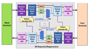
Figure 1, Illustration of the 3R Repeater/Regenerator – during Good/Normal Conditions.

Please note that I have grayed out the non-relevant portions of Figure 1 to focus our discussion on this Defect Declaration to the RDI Generation mechanism on the West-side of the 3R Repeater/Regenerator circuit.

Let’s discuss the case where we will transmit the RDI indicator.

Example # 2 – The dLOS/Abnormal Condition

Figure 2 presents another simple illustration of a 3R Repeater/Regenerator.

However, in this figure, there is an impairment in the signal that originates from the West Terminal such that our Network Element is now declaring the dLOS (Loss of Signal) defect with this signal.

It is possible that a backhoe or some other mishap severed this signal.

Nonetheless, this means that our 3R Repeater/Regenerator is no longer receiving its signal from the West Terminal.

In this case, the 3R Repeater/Regenerator will respond by doing all the following:

  • The Receive Line Interface (W) or the Receive Framer (W) blocks will declare the dLOS (Loss of Signal) defect with the signal that it is receiving from the West Terminal.
  • The Transmit Framer (E) and the Transmit Line Interface (E) (which sit directly behind the Receive Line Interface and Framer blocks – that are declaring the dLOS condition) will now transmit the AIS indicator (to the East Terminal) as we discussed in the AIS post of this blog.
  • Additionally, the Receive Line Interface (W) and/or the Receiver Framer (W) blocks will also command its “near-end” transmitting circuitry [e.g., the Transmit Framer (W) and Transmit Line Interface (W) blocks] to start sending the RDI signal, back out to the West Terminal.

Figure 2 illustrates the dLOS/RDI Transmission Condition for our 3R Regenerator/Repeater.

3R Repeater/Regenerator when transmitting RDI

Figure 2, Illustration of the 3R Repeater/Regenerator – during the dLOS/Abnormal Condition

The Transmit Framer (W) and Transmit Line Interface (W) blocks will send the RDI indicator to the West Terminal for as long as the Receive Line Interface (W) and the Receive Framer (W) blocks declare the dLOS defect within the signal they are receiving from the West Terminal.

The Transmit Framer (W) and Transmit Line Interface (W) blocks will stop sending the RDI indicator once the Receive Line Interface (W) and the Receive Framer (W) blocks clear the dLOS defect and starts to receive good/normal data from the West Terminal.

In addition to the dLOS defect, the Network Element will transmit the RDI Indicator (upstream) in response to any other service-affecting defects, such as:

  • OTN Applications (Sending the SM-BDI or PM-BDI Indicator)
    • dLOF – Loss of Frame defect
    • dLOM – Loss of Multi-Frame defect
    • dLOFLANE – Loss of Frame defect for Logical Lane (for OTL3.4 or OTL4.4 applications)
    • dLOL – Loss of Lane Alignment defect (for OTL3.4 or OTL4.4 applications)
    • dLOFLOM – Loss of Frame and Multi-Frame defect (for Multiplexed Applications)
    • dLOOMFI – Loss of OMFI defect (for Multiplexed Applications using an ODU4 server signal)
    • dPLM – Payload Type Mismatch (for Multiplexed Applications)
    • dTIM – Trail Trace Identifier Mismatch defect

Please check out the appropriate blog posts to learn more about the SM-BDI or PM-BDI indicators for OTN applications.

Why do we bother to transmit the RDI Signal?

The main reason we send the RDI signal (back to upstream equipment) in response to service-affecting defects is to alert that NE that there is a service-affecting defect within its output signal between its location and that of the next downstream NE.

This notification aids in troubleshooting and system debugging of fault conditions in the network.

Inflation’s Got You Down? Our Discounts Can Help You Beat Inflation and Make You an Expert on OTN!! Click on the Banner Below to Learn More!!!

Discounts Available for a Short Time!!!