This post presents the 8th of the 11 Videos that covers training on Performance Monitoring at the OTUk Layer. This post focuses on the Sink Direction OTU-Layer Atomic Functions.
OTN – Lesson 9 – Video 8 – OTU Layer Sink Direction Circuitry/Functionality – Part 6
This blog post includes another video that continues our discussion of the OTUk_TT_Sk Atomic Function. In this video, we focus on the following aspects of this function.
How it declares and clears the dIAE (Input Alignment Error) Defect Condition
How it declares and clears the dBIAE (Backward Input Alignment Error) Defect Condition.
The dTIM (Trail Trace Identifier Mismatch) Defect Condition.
The dDEG (Section – Signal Degrade) Defect Condition
The type of signals that the OTUk_TT_Sk function outputs via the OTUk_AP Interface – particularly the AI_TSF and AI_TSD output signals.
This post briefly defines and describes Consequent Equations that ITU-T G.798 uses for OTN Applications.
What are Consequent Equations, and How Should You Interpret Them?
The purpose of this blog post is two-fold.
To describe the concept of Consequent Equations and
To discuss how we can use and interpret these Consequent Equations.
Introduction
Many ITU Standards (such as ITU-T G.798 for OTN Applications) will discuss many aspects of defects. These standards will define defects such as dAIS (Alarm Indication Signal) and dLOM (the Loss of Multi-frame).
These same standards will also define the criteria that an OTN Network Element (be it an STE or PTE) should use to declare or clear a given defect.
For example, ITU-T G.798 specifies all of the following defects that an OTN STE can declare and clear.
How should an STE/PTE Respond Whenever it Declares a Defect?
However, what else should an STE do whenever it declares (for example) the dLOF defect condition?
Does this STE have a responsibility to notify other STEs of this defect?
Similarly, what else should a PTE do whenever it declares (for example) the dTIM (ODUk-TIM) defect condition?
Again, does this PTE have a responsibility to notify other nearby PTEs of this defect?
The short answer to both of these questions is, “Yes, for those specific defects that I mentioned, they do have a responsibility to notify upstream and downstream equipment of the occurrence of those defect conditions.”
However, to confuse things, the PTE/STE must notify upstream and downstream PTE/STE whenever some defects occur, but not others.
How Do We Sort out This Confusion?
The Answer: Consequent Equations.
Let’s assume that a certain STE is declaring the dLOF Defect condition, as shown below in Figure 1.
Figure 1, Illustration of the STE (e.g., the OTSi/OTUk-a_A_Sk Atomic Function) declares the dLOF defect condition.
What happens next?
At this point, let’s write down the Consequent Equation that pertains to this STE (or the OTSi/OTUk-a_A_Sk function in this case):
AI_TSF-P is the current (logical) state of the AI_TSF-P input pin (to the OTSi/OTUk-a_A_Sk atomic function).
This consequent equation states that the STE (or OTSi/OTUk-a_A_Sk function) will assert its CI_SSF output pin anytime it declares any of the following defect conditions:
This consequent equation also states that the STE (the OTSi/OTUk-a_A_Sk function) will assert the CI_SSF output pin anytime the upstream atomic function asserts the AI_TSF input to this function.
NOTE: Please see the OTSi/OTUk_A_Sk Function Post for more information about this particular Atomic Function.
So What Does All of This Mean?
In Figure 2, I show the OTSi/OTUk_A_Sk function now asserting its CI_SSF output pin because it is currently declaring the dLOF defect condition.
Figure 2, Illustration of the OTSi/OTUk_A_Sk Atomic Function asserting its CI_SSF output because it is currently declaring the dLOF defect condition.
Please note that the CI_SSF output (from the OTSi/OTUk_A_Sk function) is connected to the CI_SSF input of the (downstream) OTUk_TT_Sk function.
OK, that’s great. The above Consequent Equation states that the STE (e.g., the OTSi/OTUk_A_Sk function will assert the CI_SSF output pin whenever it declares the dLOF defect.
How does that alert any other STE/PTE of the OTSi/OTUk_A_Sk function declaring the dLOF defect?
Answer: There is more to this, and it involves more Consequent Equations.
In Figure 3, I show the OTUk_TT_Sk and the OTUk/ODUk_A_Sk Atomic Functions.
I also show that the upstream (OTSi/OTUk_A_Sk function) circuitry is now asserting the CI_SSF input (to the OTUk_TT_Sk function) – as we described above.
Figure 3, Illustration of the OTUk_TT_Sk and OTUk/ODUk_A_Sk functions – with upstream circuitry asserting the CI_SSF input pin.
Now, the OTUk_TT_Sk Atomic Function happens to have two sets of Consequent Equations:
I will list each of these equations below.
aTSF <- CI_SSF or dAIS or (dTIM and (NOT TIMActDis))
aBDI <- CI_SSF or dAIS or dTIM
I will explain each of these equations below.
The First Consequent Equation – OTUk_TT_Sk Function
Let’s start with the first Consequent Equation for the OTUk_TT_Sk function.
aTSF <- CI_SSF or dAIS or (dTIM and (NOT TIMActDis))
Where:
aTSF is the current state of the AI_TSF output of the OTUk_TT_Sk Atomic Function.
CI_SSF is the current state of the CI_SSF input of the OTUk_TT_Sk Atomic Function.
dAIS is the current state of the dAIS defect condition, and
This Consequent Equation states that the OTUk_TT_Sk Atomic Function should assert the AI_TSF output signal anytime it declares any of the following defect conditions.
dTIM – Trail Trace Identifier Mismatch Defect
dAIS – AIS Defect
This Consequent Equation also states that the OTUk_TT_Sk function should assert the AI_TSF output whenever the upstream circuitry (e.g., the OTSi/OTUk_A_Sk function) asserts the CI_SSF input pin.
In Figure 4, I show the OTUk_TT_Sk function asserting its AI_TSF output pin because the upstream OTSi/OTUk_A_Sk function is asserting the CI_SSF input pin (to this function).
Figure 4, The OTUk_TT_Sk Atomic Function asserts the AI_TSF output pin because the upstream OTSi/OTUk_A_Sk function is asserting its CI_SSF input pin.
OK, now let’s look at the second Consequent Equation for the OTUk_TT_Sk Function.
The Second Consequent Equation – OTUk_TT_Sk Function
aBDI <- CI_SSF or dAIS or dTIM
Where:
aBDI is the state of the RI_BDI output (of the Remote Port Interface) of the OTUk_TT_Sk function.
Earlier in this post, we have defined CI_SSF, dAIS, and dTIM.
Therefore, this Consequent Equation states that the OTUk_TT_Sk function will assert the RI_BDI output pin anytime it declares the dAIS or dTIM defect conditions.
This equation also states that the OTUk_TT_Sk function will also assert the RI_BDI output pin anytime the upstream circuitry asserts the CI_SSF input (to the OTUk_TT_Sk function).
If you recall from the OTUk_TT_So and OTUk_TT_Sk posts, I state that anytime the OTUk_TT_Sk function asserts the RI_BDI output pin, it will command its collocated OTUk_TT_So function to transmit the OTUk-BDI indicator back out to the remote end.
I show this phenomenon below in Figure 5.
Figure 5, The OTUk_TT_Sk function asserts its RI_BDI output pin, commanding its Collocated OTUk_TT_So function to transmit the BDI (Backward Defect Indicator) back to the upstream STE because its CI_SSF is being driven HIGH.
Figure 5 shows that because the STE (OTSi/OTUk_A_Sk function) declared the dLOF defect, the downstream OTUk_TT_Sk function responded by commanding its collocated OTUk_TT_So function to transmit the OTUk-BDI indicator back to the upstream STE (the source of the defective OTUk signal).
However, we’re not done yet.
Since the OTUk_TT_Sk function is also asserting its AI_TSF output, it is also asserting the AI_TSF input to the (down-stream) OTUk/ODUk_A_Sk atomic function.
Has Inflation got You Down? Our Price Discounts Can Help You Fight Inflation and Help You to Become an Expert at OTN!!! Click Below to Learn More!!
Let’s move on to the OTUk/ODUk_A_Sk Atomic Function
As you can see in Figure 5, the OTUk_TT_Sk function, by asserting its AI_TSF output pin, is also asserting the AI_TSF input pin to the OTUk/ODUk_A_Sk function.
And the OTUk/ODUk_A_Sk function comes with several Consequent Equations of its own.
aSSF <- AI_TSF and (not MI_AdminState = LOCKED), and
aAIS <- AI_TSF and (not MI_AdminState = LOCKED)
Let’s take each of these equations, one at a time.
The First Consequent Equation – OTUk/ODUk_A_Sk Function
aSSF <- AI_TSF and (not MI_AdminState = LOCKED)
Where:
aSSF is the current state of the CI_SSF output pin (from the OTUk/ODUk_A_Sk function).
MI_AdminState reflects the current state of the MI_AdminState input signal (which the System Operator can set).
This Consequent Equation states that the OTUk/ODUk_A_Sk function will automatically assert its CI_SSF output signal whenever the upstream circuitry asserts its AI_TSF input, provided that the System Operator has not put the OTUk/ODUk_A_Sk function into the LOCKED state.
In Figure 6, I show the OTUk/ODUk_A_Sk function asserting its CI_SSF output pin because the upstream circuitry is asserting its AI_TSF input pin.
Figure 6, The OTUk/ODUk_A_Sk function asserts its CI_SSF output pin because the upstream circuitry (e.g., the OTUk_TT_Sk and OTSi/OTUk_A_Sk functions) is asserting its AI_TSF input pin.
I should also point out that APS (Automatic Protection Switching) systems often trigger (and start protection switching) whenever the OTUk/ODUk_A_Sk function asserts its CI_SSF output pin.
Now, let’s move on to the next Consequent Equation.
The Second Consequent Equation – OTUk/ODUk_A_Sk Function
If aAIS = TRUE, then the OTUk/ODUk_A_Sk function is overwriting its output signal with the ODUk-AIS Maintenance signal.
Conversely, if aAIS is FALSE, then the OTUk/ODUk_A_Sk function transmits an ODUk data stream, carrying regular client traffic.
Therefore, this Consequent Equation states that the OTUk/ODUk_A_Sk function will transmit the ODUk-AIS Maintenance Signal anytime the upstream circuitry pulls its AI_TSF input TRUE; provided that the System Operator has NOT put the OTUk/ODUk_A_Sk function into the LOCKED State.
In Figure 7, I illustrate the OTUk/ODUk_A_Sk function transmitting the ODUk-AIS Maintenance Signal because upstream circuitry (e.g., the OTUk_TT_Sk and OTSi/OTUk_A_Sk functions) is asserting its AI_TSF input.
Figure 7, The OTUk/ODUk_A_Sk function replaces the ODUk signal (carrying client data) with the ODUk-AIS Maintenance Signal whenever upstream circuitry asserts its AI_TSF input.
Then, we could state that if the OTN STE declares the dLOF defect (as we discussed earlier in this post), then that same OTN STE will do all of the following:
It will transmit the OTUk-BDI indicator back towards the upstream STE.
The OTN STE will also replace the missing (or defective) ODUk data stream (carrying client traffic) with the ODUk-AIS Maintenance Signal, and
It will also trigger APS (Automatic Protection Switching) activities by asserting the CI_SSF output (from the OTUk/ODUk_A_Sk function).
I show a drawing of these actions below in Figure 8.
Figure 8, Illustration of the OTN STE responding to the dLOF Defect Condition
Conclusion
Thanks to Consequent Equations, we can define and predict how an OTN STE or PTE will respond to certain defects.
I have presented Consequent Equations in each post pertaining to OTN Atomic Functions.
Clueless about OTN? We Can Help!! Click on the Banner Below to Learn More.
Discounts Available for a Short Time!!!
Click on the Image below to See More OTN- or Protection-Switching-Related Posts
This post briefly defines and explains what Defect Correlation means. In short, the Defect Correlation equations will specify how we expect a system to respond to a specific defect condition.
What is Defect Correlation, and How Should You Interpret It?
The purpose of this blog post is two-fold.
To describe the concept of Defect Correlation and
To discuss how to interpret the meaning of Defect Correlation and their Equations.
Introduction
Numerous ITU Standards (such as ITU-T G.798 for OTN applications) will define various aspects of defects. These standards will define a defect, such as dLOS (the Loss of Signal) and dLOF (the Loss of Frame).
These standards will (sometimes) describe the conditions that an OTN Network Element (be it an STE or PTE) should use to declare or clear a given defect.
For instance, ITU-T G.798 specifies all of the following defects that an OTN STE can declare and clear.
Figure 1, The OTSi/OTUk-a_A_Sk Atomic Function, declares the dLOS Defect Condition.
In either of these cases, it is clear that this OTN STE should declare the dLOS-P defect condition.
How about the dLOF Condition?
However, if that same OTN STE is not receiving any discernable signal from the remote STE, it is safe to say that it will not be receiving the FAS fields (within this now non-existent incoming data stream).
Should this OTN STE also declare the dLOF defect as well?
In Figure 2, I illustrate the OTSi/OTUk-a_A_Sk function, declaring the dLOF defect condition and the dLOS-P defect condition.
Figure 2, The OTSi/OTUk-a_A_Sk function declaring the dLOF and dLOS-P Defect Conditions
Clueless about OTN? We Can Help!! Click on the Banner Below to Learn More!!!
Corporate Discounts Available!!!
What about the dLOM Condition?
And since the OTN STE is not receiving any FAS field bytes, it cannot locate the MFAS bytes.
Should this OTN STE also declare the dLOM defect too?
In Figure 3, I illustrate the OTSi/OTUk-a_A_Sk function, declaring the dLOM, dLOF, and dLOS-P Defect conditions.
Figure 3, The OTSi/OTUk-a_A_Sk Atomic Function declaring the dLOM, dLOF, and dLOS-P Defect Conditions
How about the dTIM Condition?
Finally, since our OTN STE is not receiving any discernable signal (from the remote STE), and it cannot locate the boundaries of each incoming OTUk frame, it will certainly not obtain a Trail Trace Identification Message that matches that of the “Expected Trail Trace Identification” Message.
Should this OTN STE also declare the dTIM defect as well?
Figure 4, The OTUk_TT_Sk Atomic Function (downstream from the OTSi/OTUk-a_A_Sk Function) declares the dTIM defect.
Many Defects, all due to the dLOS-P Condition
In this scenario, a Loss of Signal event would cause the OTN STE to declare the dLOS, dLOF, dLOM, and dTIM defect conditions.
The OTN STE will accurately declare all four defect conditions because conditions warrant that the STE declare each of these defects.
However, allowing an STE to declare multiple defects (e.g., dLOS, dLOF, dLOM, and dTIM) can be confusing to both System-Management and the System Operator.
I could take this exercise even further and include some of the PTE/ODUk-related defects that an OTN PTE would declare (e.g., ODUk-AIS), all because of the dLOS-P condition. But I think that you get my point.
Whenever a service-affecting defect occurs, the OTN STE needs to alert System Management of a concise description of the problem (just dLOS-P in this case).
The intent should be to help the System Operator isolate the root cause of these problems.
We should not be bombarding the System Operator with a whole slew of defects, which are just artifacts of a single defect.
If the OTN STE declares the dTIM, dLOM, dLOF, and dLOS-P defects, the root cause of this problem has nothing to do with a mismatch in the Trail-Trace Identification Message.
Hence the Purpose of Defect Correlation
The purpose of Defect Correlation and Defect Correlation equations is to establish and report ONLY the root cause of problems to System Management.
The Defect Correlation Equations accomplishes this by creating a hierarchy of defects.
I’ll explain this.
Let’s list some Defect Correlation Equations for the OTSi/OTUk_A_Sk and OTUk_TT_Sk Atomic Functions.
cLOF ⇐ dLOF and (NOT dLOS-P) and (NOT dAIS) and (NOT AI_TSF-P)
cLOM ⇐ dLOM and (NOT dLOS-P) and (NOT dLOF) and (NOT dAIS) and (NOT AI_TSF-P)
Let’s also include the following Consequent Equation to bridge the OTUk_TT_Sk function to the OTSi/OTUk_A_Sk function.
aSSF ⇐ dLOS-P or dAIS or dLOF or dLOM or AI_TSF-P
For the OTUk_TT_Sk Function
In this case, we will focus on the Defect Correlation equation that pertains to the dTIM defect condition.
cTIM ⇐ dTIM and (NOT CI_SSF) and (NOT dAIS)
So Now Let’s Study some of these Defect Correlation Equations
Let’s start with the first equation for the OTSi/OTUk-a_A_Sk function.
cLOS-P ⇐ dLOS-P and (NOT AI_TSF-P)
Where:
cLOS-P is the correlated defect value of the dLOS-P defect state.
dLOS-P is the current state of the dLOS-P defect condition that the OTSi/OTUk_A_Sk function will declare or clear.
AI_TSF-P is the current state of the AI_TSF-P (Trail Signal Fail – Path Indicator) Input to the OTSi/OTUk-A_Sk function.
In this equation, the parameter that begins with the letter “c” is the correlated defect parameter (or defect) state that we ultimately report to System Management.
This equation states that we should only set the variable cLOS-P to TRUE if dLOS-P is TRUE.
In other words, we should only report the Loss of Signal condition (e.g., setting cLOS-P to TRUE) if the STE circuitry declares the dLOS-P defect (due to a lack of signal activity within the Clock Recovery Block, for example).
This equation also states that we should NOT set cLOS-P to TRUE because the upstream Optical Circuitry is declaring some other defect condition and is then asserting its AI_TSF-P output – towards the OTSi/OTUk_A_Sk function).
I show a TRUTH TABLE for this Defect Correlation Equation below in Table 1.
Table 1, TRUTH TABLE for the Defect Correlation Equation, cLOS-P ⇐ dLOS-P AND (NOT AI_TSF-P)
dLOS-P Defect
AI_TSF-P State
cLOS-P State
Comment
Cleared
FALSE
0
Declared
FALSE
1
Sets cLOS-P to TRUE, because dLOS-P is declared.
Don't Care
TRUE
0
We set cLOS-P to 0 when AI_TSF-P is TRUE.
Let’s look at another Defect Correlation Equation.
cLOF ⇐ dLOF and (NOT dLOS-P) and (NOT dAIS) and (NOT AI_TSF-P)
Where:
cLOF is the correlated value of the dLOF defect state.
dAIS is the current state of the dAIS defect condition within the OTSi/OTUk_A_Sk function.
In this equation, we are stating that we should only set cLOF = TRUE (and report the Loss of Frame condition to System Management) if the STE circuitry declares the dLOF condition.
This equation also states that we should NOT be setting cLOF = TRUE (and report the Loss of Frame Condition to System Management) if:
The STE is also declaring the dLOS-P defect, or
declaring the dAIS (OTUk-AIS) defect, or
If the upstream Optical Components assert the AI_TSF-P input to the OTSi/OTUk_A_Sk function.
If any of the three items (above) are TRUE, then we must set cLOF = FALSE.
I show the TRUTH TABLE for this Defect Correlation Equation below in Table 2.
Table 2, The TRUTH TABLE for the Defect Correlation Equation, cLOF ⇐ dLOF AND (NOT dLOS-P) AND (NOT dAIS) AND (NOT AI_TSF-P)
dLOF Defect Condition
dLOS-P Defect Condition
dAIS Defect Condition
AI_TSF-P State
cLOF State
Comments
Cleared
Cleared
Cleared
FALSE
Cleared
Declared
Cleared
Cleared
FALSE
Declared
We assert cLOF because we are declaring the dLOF Defect
Don't Care
Declared
Cleared
FALSE
Cleared
We set cLOF = 0 whenever dLOS-P is declared.
Don't Care
Cleared
Declared
FALSE
Cleared
We set cLOF = 0 whenever dAIS is declared.
Don't Care
Cleared
Cleared
TRUE
Cleared
We set cLOF = 0 whenever AI_TSF-P is driven TRUE.
At the risk of “whipping a dead horse,” I will show one more example.
cTIM ⇐ dTIM and (NOT CI_SSF) and (NOT dAIS)
Where:
cTIM is the correlated value of the dTIM defect state.
CI_SSF is the current state of the CI_SSF (Server Signal Fail Indicator) input pin to the OTUk_TT_Sk function.
If the STE circuitry declares this defect, this equation states that we must only report the Trail Trace Identifier Mismatch Defect (and set cTIM = TRUE).
This equation also states that we MUST NOT set cTIM = TRUE if any of the following is true.
If the upstream Optical Components assert the AI_TSF-P input to the OTSi/OTUk_A_Sk function.
If aSSF = TRUE, then the OTSi/OTUk_A_Sk function will assert the CI_SSF output signal (towards the OTUk_TT_Sk function).
Finally, we get to the bottom line.
These equations state that the STE MUST NOT set cTIM = TRUE (and MUST NOT report the Trail Trace Identifier Mismatch defect to System Management) if any of the following defect conditions are TRUE.
dLOS-P
dAIS
dLOF
dLOM
If the AI_TSF-P signal (from the upstream Optical Components) is HIGH.
Summary
I believe that you can see that using Defect Correlation Equations makes Defect Reporting and System-Management MUCH EASIER.
Has Inflation got You Down? Our Price Discounts Can Help You Fight Inflation and Help You Become an Expert on OTN!! Click on the Banner Below to Learn More!!!
Discounts Available for a Short Time!!
CLICK on the Image below for More OTN Related Blog Posts
This blog post briefly describes the OTUk_TT_Sk (OTUk Trace Termination Sink) Atomic function. This function will check for dDEG and dTIM defect conditions. It will also detect and flag SM-BIP-8 Errors.
What is the OTUk_TT_Sk Atomic Function?
We formally call the OTUk_TT_SkAtomic Function the OTUk Trail Termination Sink function.
Introduction
The OTUk_TT_Sk function is any circuit that accepts an OTUk data stream from the upstream OTSi/OTUk_A_Sk function (for OTU1 and OTU2 applications) or the upstream OTSiG/OTUk_A_Sk function (for OTU3 or OTU4 applications) and extracts and processes the data within the OTUk Section Monitoring Overhead (OTUk-SMOH) from the incoming OTUk signal.
The OTUk_TT_Sk function will evaluate this data to check for various defects and errors.
If you recall, from our discussion of the OTUk/ODUk_A_So and OTUk_TT_So functions, those two particular functions will take an ODUk signal and work together to create an OTUk data stream with some newly computed OTUk-SMOH.
The OTUk_TT_So function will then route this OTUk data stream to the OTSi/OTUk-a_A_So (for OTU1/2 applications) or the OTSiG/OTUk-a_A_So functions (for OTU3/4 applications).
These functions will condition the OTUk signal for transport. Next, one of these functions will route this OTUk signal through other circuitry that will convert this OTUk data stream into the optical format and transport this data stream over optical fiber.
A receiving Network Element will receive this optical signal and convert this data back into the electrical format. This electrical signal will pass through the OTSi/OTUk-a_A_Sk atomic function (for OTU1/2 applications) or the OTSiG/OTUk-a_A_Sk atomic function (for OTU3/4 applications) before it finally reaches the OTUk_TT_Sk function.
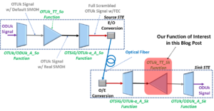
I illustrate where the OTUk_TT_Sk function “fits in the big picture” below in Figure 1.
Figure 1, Illustration of Unidirectional Connection between a Source STE and a Sink STE with the OTUk_TT_Sk function highlighted.
Once this OTUk data arrives at the OTUk_TT_Sk function, it will perform the following tasks on this data stream.
Extracts and Processes the OTUk-SMOH within the incoming OTUk Data-Stream
The OTUk_TT_Sk function will accept this OTUk data stream and extract and process the OTUk-SMOH data from the incoming OTUk signal. The OTUk_TT_Sk function will evaluate this data to check for various defects and errors.
In other words, the OTUk_TT_Sk function will evaluate the OTUk_SMOH (the OTUk_TT_So function, at the remote STE) created. The OTUk_TT_Sk function will evaluate the OTUk-SMOH to check and see if it should declare certain types of defect conditions or if certain kinds of errors have occurred within this OTUk signal during transmission over optical fiber, as we describe below.
Clueless about OTN? We Can Help!!! Click on the Banner Below to Learn More!!!
Corporate Discounts Available!!
Detect and Flag Defects and Errors within the Incoming OTUk Data-Stream
More specifically, the OTUk_TT_So function will check the following defect conditions for (and declare or clear).
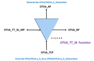
Figure 2 presents a simple illustration of the OTUk_TT_Sk function.
Figure 2, Simple Illustration of the OTUk_TT_Sk Atomic Function
The Interfaces within the OTUk_TT_Sk Atomic Function
Figure 2 shows that this function consists of four different interfaces.
OTUk_TCP – The OTUk Termination Connection Point: This is where the function user supplies data (which most likely came from an upstream OTSi/OTUk-a_A_Sk or OTSiG/OTUk-a_A_Sk function) to the OTUk_TT_Sk function. This data will typically consist of the entire OTUk data stream (without the FEC, which was already decoded by the upstream OTSi/OTUk-a_A_Sk or OTSiG/OTUk-a_A_Sk function).
OTUk_AP – The OTUk Access Point: This is where the function outputs OTUk data, clock, frame, and multi-frame signals (of the incoming OTUk data-stream) to downstream circuitry (towards the OTUk/ODUk_A_Sk function).
OTUk_TT_Sk_MP – The Function Management Point: This interface permits the function-user to exercise control and monitor the activity within the OTUk_TT_Sk function. Some information the user can obtain from the Management Point includes Performance Monitoring and Correlated Defect Identification.
OTUk_TT_RP – The Function Remote Point: This interface permits the function-user to output some information to a collocated OTUk_TT_So function. This information includes the BDI, BEI, and BIAE indicators. The collocated OTUk_TT_So function will respond to this signaling (from the OTUk_TT_Sk function – via the RP port) by transmitting the BEI values, BDI, and BIAE indicators back out to the Remote STE, as appropriate.
A Closer Look at the Interfaces within the OTUk_TT_Sk Function.
We will now take a closer look at these interfaces below.
The OTUk_TCP (Termination Connection Point) Interface
The OTUk_TT_Sk function accepts an OTUk data stream from either the upstream OTSi/OTUk-a_A_Sk or OTSiG/OTUk-a_A_Sk function via the OTUk_TCP Interface.
The data that either the OTSi/OTUk-a_A_Sk or the OTSiG/OTUk-a_A_Sk function outputs are a full-blown OTUk frame (that has been descrambled) by those functions.
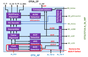
Figure 3 presents a functional block of the OTUk_TT_Sk function.
Figure 3, Functional Block Diagram of the OTUk_TT_Sk Function
Finally, Figure 3 shows that the equipment that we connect to the OTUk_TCP (of the OTUk_TT_Sk function) will supply the following signals to this function.
CI_D
CI_CK
CI_FS
CI_MFS
The OTUk_TT_Sk function will perform the following operations on each OTUk frame within this signal.
As the OTUk_TT_Sk function performs all of the above actions on the data (that it receives via the OTUk_TCP Interface), it will tally and report all of the following performance monitoring parameters to System Management (via the Management Interface).
Report and Tally the following errors
BIP-8 Errors– reported as nBIPV (to the RI_REI output) and as nN_B in performance monitoring.
BEI Count – reported as nF_B in Performance Monitoring
To provide Performance Monitoring reports on the following parameters to System Management
Whenever the user connects these three (3) output pins to similarly named pins at the collocated OTUk_TT_So function, these two functions will work together to transmit backward alarm and error information to the remote STE (the source of the OTUk data-stream that this OTUk_TT_Sk function is receiving).
Please click on the appropriate links to learn more about these backward (or far-end) indicators and how the OTUk_TT_Sk function accomplishes these forms of signaling with its collocated OTUk_TT_So function.
The OTUk_AP (Access Point) Interface (Output)
The OTUk_TT_Sk function will output the following signals via the OTUk_AP Interface.
AI_D – OTUk Adapted Information – Data Output
AI_CK – OTUk Adapted Information – Clock Output
AI_FS – OTUk Adapted Information – Frame Start Output
AI_MFS – OTUk Adapted Information – Multi-Frame Start Output
AI_TSF – OTUk Adapted Information – Trail Signal Fail (TSF) Indicator Output
AI_TSD – OTUk Adapted Information – Trail Signal Degrade (TSD) Indicator Output.
In most cases, the System Designer would route these output signals to the downstream OTUk/ODUk_A_Sk function for further processing.
AI_D, AI_CK, AI_FS, and AI_MFS will contain the remaining OTUk data-stream, clock, frame-start, and multi-frame start indicators for the OTUk/ODUk_A_Sk function.
Defect Notification – Downstream
The OTUk_TT_Sk function will assert the AI_TSF output pin anytime it declares a service-affecting defect (dTIM) itself or if the upstream circuitry (e.g., the OTSiG/OTUk-a_A_Sk or the OTSi/OTUk-a_A_Sk functions) are declaring service-affecting defects and asserting the CI_SSF input to this function.
Likewise, the OTUk_TT_Sk function will assert the AI_TSD output pin anytime it declares the dDEG (Signal Degrade) defect condition.
Consequent Actions
Consequent Action Equations specify what actions an Atomic Function should take any time (and for the duration) that it declares a certain defect. ITU-T G.798 presents the following equations for consequent actions within the OTUk_TT_Sk function.
aTSF <- CI_SSF or [dTIM and (NOT TIMActDis)]
aBDI <- CI_SSF or dTIM
aBEI <- nBIPV
aBIAE <- dIAE
aTSD <- dDEG
I will discuss each of these consequent action equations below.
aTSF <- CI_SSF or [dTIM and (NOT TIMActDis)]
Where:
aTSF is the Trail Signal Fail parameter that the OTUk_TT_Sk function will set LOW or HIGH to send current defect-state information towards downstream circuitry.
If aTSF = TRUE, then the OTUk_TT_Sk function will set its AI_TSF output HIGH. Conversely, if aTSF = FALSE, then the OTUk_TT_Sk function will set its AI_TSF output to LOW.
CI_SSF is the current state of the CI_SSF (Server Signal Fail Indicator) input from the upstream OTSi/OTUk_A_Sk or OTSiG/OTUk_A_Sk atomic functions. The OTSi/OTUk_A_Sk or OTSiG/OTUk_A_Sk function will assert this signal anytime it declares a service-affecting defect.
dTIM is the current state of the dTIM defect condition.
TIMActDis is a parameter the user can set to configure the dTIM to (optionally) drive the aTSF parameter.
This equation means that the OTUk_TT_Sk function will assert an internal signal (we call aTSF) if either of the following conditions is true.
The upstream circuitry (e.g., the OTSiG/OTUk-a_A_Sk or the OTSi/OTUk-a_A_Sk function) is asserting the CI_SSF input to this function, or
The OTUk_TT_Sk function declares the dTIM defect condition.
NOTES:
If the OTUk_TT_Sk function asserts the aTSF signal, it will indicate so by asserting the AI_TSF output pin towards downstream circuitry (e.g., the OTUk/ODUk_A_Sk function).
The AI_TSF output signal is a crucial signal for Automatic Protection Switching purposes.
Please see the OTSi/OTUk_A_Sk or OTSiG/OTUk_A_Sk posts for information on what causes these two functions to drive the CI_SSF signal HIGH.
aBDI <- CI_SSF or dTIM
This equation means that the OTUk_TT_Sk function will assert another internal signal (the aBDI signal) if either of the following conditions is true.
The upstream circuitry (e.g., the OTSiG/OTUk-a_A_Sk or the OTSi/OTUk-a_A_Sk function) is asserting the CI_SSF input to this function, or
The OTUk_TT_Sk function declares the dTIM defect condition.
NOTES:
If the OTUk_TT_Sk function asserts the aBDI signal, it will indicate so by asserting the RI_BDI output pin (via the Remote Point Interface). This signaling will command the collocated OTUk_TT_So function to set its BDI bit-field to TRUE within its next outbound OTUk frame.
The OTUk_TT_Sk function will assert the RI_BDI and AI_TSF output pins under the same conditions.
Please see the OTSi/OTUk_A_Sk or OTSiG/OTUk_A_Sk posts for information on what causes these two functions to drive the CI_SSF signal HIGH.
aBEI <- nBIPV
This equation means that the OTUk_TT_Sk function will automatically set the internal signal aBEI to the total number of BIP-8 errors detected within a given OTUk frame. This means the OTUk_TT_Sk function can set aBEI to a value between 0 and 8 within each OTUk frame.
NOTE: If the OTUk_TT_Sk function sets aBEI to a particular value, it will set the RI_BEI output pin (via the Remote Point Interface) to this same value. This signaling will command the collocated OTUk_TT_So function to set its BEI nibble-field to this same value (aBEI), within its next outbound OTUk frame, provided that RI_BIAE is set FALSE.
aBIAE <- dIAE
This equation means that the OTUk_TT_Sk function will assert the internal signal, aBIAE, if it declares the dIAE (Input Alignment Error) defect condition.
NOTES:
If the OTUk_TT_Sk function is asserting the aBIAE signal, it will indicate so by asserting the RI_BIAE output pin (via the Remote Point Interface). This signaling will command the collocated OTUk_TT_So function to set the BEI/BIAE nibble-field to reflect the BIAE condition within its next outbound OTUk frame.
The OTUk_TT_Sk function will NOT assert the AI_TSF or RI_BDI output signals because it declares the dIAE defect condition.
aTSD <- dDEG
This equation means that the OTUk_TT_Sk function will assert the internal signal aTSD anytime it declares the OTUk-dDEG (Signal Degrade) defect condition.
NOTES:
If the OTUk_TT_Sk function is asserting the aTSD condition, it will indicate so by asserting the AI_TSD output signal towards the downstream circuitry (e.g., the OTUk/ODUk_A_Sk function in this case).
The OTUk_TT_Sk function will NOT assert the RI_BDI output signal because it declares the dDEG defect condition.
The AI_TSD output signal is an essential signal for Automatic Protection Switching purposes.
The OTUk_TT_Sk Function Pin Description
Table 1 presents a Description of each of the Input and Output pins of the OTUk_TT_Sk function.
Table 1, Pin Description of the OTUk_TT_Sk Atomic Function
Signal Name
Type
Description
OTUk_TCP Interface
CI_D
Input
OTUk Characteristic Information - Data Input:
The OTUk_TT_Sk function will accept this data from either the upstream OTSi/OTUk-a_A_Sk or OTSiG/OTUk-a_A_Sk function via this input pin. The OTUk_TT_Sk function will then perform the following actions on this data.
- It will extract out and process the SMOH (Section Monitoring Overhead) and
-- Compute and Verify the BIP-8 data and it will detect and flag any BIP-8 errors within each OTUk frame.
-- It will extract out the Section Monitoring Byte and check the state of the BDI and IAE bit-fields.
-- It will read in the value of the BEI/BIAE nibble field and check for the BIAE indicator.
-- It will also read in and tally all non-zero (and non-BIAE) BEI values and BIP-8 errors.
-- It will extract out the TTI message and compare this read-out value with that of the expected TTI Message.
As the OTUk_TT_Sk performs all of these tasks it will declare or clear the following defect conditions (as warranted).
- dBDI
- dTIM
- dIAE
- dBIAE
- dDEG
It will tally the following events for Performance Monitoring purposes.
- pIAE - Number of seconds in which the OTUk_TT_Sk function declared the dIAE defect.
- pN_BIAE - Number of seconds in which the OTUk_TT_Sk function declared the dBIAE defect.
- pN_EBC - Number of Near-End Errored Block Counts (BIP-8 Errors).
- pN_DS - Number of Defect Seconds (seconds in which the OTUk_TT_Sk (or upstream circuitry) declared certain near-end defect conditions.
- pF_EBC - Number of Far-End Errored Block Counts (BEI Count)
- pF_DS - Number of Far-End Defect Seconds (seconds in which the OTUk_TT_Sk function is declaring the dBDI defect condition).
The OTUk_TT_Sk function will sample this data on one of the edges of the CI_CK input clock signal.
CI_CK
Input
OTUk Characteristic Information - Clock Input:
The OTUk_TCP Interface will use this clock input signal to sample all of the following input signals.
- CI_D
- CI_FS
- CI_MFS
- CI_SSF
This clock signal also functions as the timing source of the OTUk_TT_Sk function.
CI_FS
Input
OTUk Characteristic Information - Frame Start Input:
The upstream circuitry should drive this input signal HIGH whenever it is applying the very first bit/byte of a new OTUk frame to the CI_D input.
The upstream circuitry should drive this input signal HIGH once for each incoming OTUk frame.
CI_MFS
Input
OTUk Characteristic Information - Multi-Frame Start Input:
The upstream circuitry should drive this input signal HIGH whenever it is applying the very frist bit/byte of a new OTUk superframe to the CI_D input.
The upstream circuitry should drive this input signal HIGH once for each incoming OTUk superframe (or once every 256 OTUk frames).
CI_SSF
Input
OTUk Characteristic Information - Server Signal Failure Indicator Input:
This input pin indicates whether or not the upstream circuitry is declaring a service-affecting defect with the OTUk data-stream (that it is applying to the CI_D input). These service-affecting defects include:
- dLOF
- dLOM
- dAIS (for OTU1 or OTU2 applications only).
This signal is functionally equivalent to the AIS indicator.
LOW - Indicates that the upstream circuitry is NOT declaring a service-affecting defect with the OTUk signal (being applied to the CI_D input).
HIGH - Indicates that the upstream circuitry IS declaring a service-affecting defect with the OTUk signal (being applied to the CI_D input).
OTUk_AP Interface
AI_D
Output
OTUk Adapted Information - Data Output:
The OTUk_TT_Sk function will output the OTUk data, after it has passed through and been processed by this function. This data will typicallly be routed to the OTUk/ODUk_A_Sk function for further processing.
This data will be updated (and output) synchronously with the AI_CK clock output signal.
AI_CK
Output
OTUk Adapted Information - Clock Output:
The OTUk_TT_Sk function will update/output signals via the OTUk_AP Interface on one of the edges of this clock output signal.
- AI_D
- AI_FS
- AI_MFS
- AI_TSF
- AI_TSD
AI_FS
Output
OTUk Adapted Information - Frame Start Output:
The OTUk_AP Interface will drive this output signal HIGH whenever it is also driving the very first bit/byte of a new OTUk frame via this AI_D output.
The OTUk_AP Interface will drive this output HIGH once for each outbound OTUk frame.
AI_MFS
Output
OTUk Adapted Information - Multiframe Start Output:
The OTUk_AP Interface will drive this output signal HIGH whenever it is also driving the very first bit/byte of a new OTUk superframe via the AI_D output.
The OTUk_AP Interface will drive this output HIGH once for each oubound OTUk superframe.
AI_TSF
Output
OTUk Adapted Information - Trail Signal Fail Output Indicator Output:
The OTUk_TT_Sk function will indicate whether or not it is declaring the Trail-Signal Fail (TSF) condition. The OTUk_TT_Sk function will declare the TSF condition, if it also declares any of the following defect conditions.
- dTIM
- SSF (if the CI_SSF input was driven HIGH due to any of the following defects within the upstream circuitry).
-- dLOF
-- dLOM
-- dAIS (OTU1/OTU2 applications only).
LOW - Indicates that the OTUk_TT_Sk function is NOT currently declaring the TSF indicator.
HIGH- Indicates that the OTUk_TT_Sk function is currently declaring the TSF indicator.
AI_TSD
Output
OTUk Adapted Information - Trail Signal Declared Indicator Output:
The OTUk_TT_Sk function will use this output signal to indicate if it is declaring the Trail-Signal Defect (TSD) Condition. The OTUk_TT_Sk function will declare the TSD condition if it also declares the dDEG (Signal Degrade) defect condition.
LOW - Indicates that the OTUk_TT_Sk function is NOT currently declaring the TSD indicator.
HIGH - Indicates that the OTUk_TT_Sk function is currently declaring the TSD indicator.
OTUk_RP Interface
RI_BEI
Output
OTUk Remote Point Information - Backward Error Indicator:
As the OTUk_TT_Sk function computes and verifies the BIP-8 values (within the OTUk signal that it is receiving via the CI_D input), it will output date through this output to reflect the number of BIP-8 errors that it is declaring within each incoming OTUk frame. This output signal will be connected to the RP input of its collocated OTUk_TT_So function.
If the OTUk_TT_Sk detects ZERO BIP-8 errors within the most recently received OTUk frame, then it will set RI_BEI = 0 for that OTUk frame period.
Likewise, if the OTUk_TT_Sk function detects five (5) BIP-8 errors within the most recenlty received OTUk frame, then it will set RI_BEI = 5 for that OTUk frame period.
RI_BIAE
Output
OTUk Remote Point Information - Backward Input Alignment Error Indicator:
If the OTUk_TT_Sk function declares the dIAE defect condition, then it will set the RI_BIAE indicator true. This output signal will be connected to the corresponding RP Input of the collocated OTUk_TT_So function.
The collocated OTUk_TT_So function is expected to overwrite the BEI nibble-field (within the next outbound OTUk frame).
Please see the OTUk_TT_So function post for more details on this topic).
RI_BDI
Output
OTUk Remote Point Information - Backward Defect Indicator:
If the OTUk_TT_Sk function declares any of the following defect conditions, then it will set this output pin TRUE.
- dTIM
- CI_SSF
The user should connect this output signal to the RI_BDI input of the collocated OTUk_TT_So function.
The collocated OTUk_TT_So function is expected to set the BDI bit-field (within the Section Monitoring byte of the SMOH) to "1" within the next outbound OTUk frame, if this output pin is TRUE.
Otherwise, the OTUk_TT_So function should set the BDI bit-field to "0" within the very next outbound OTUk frame.
OTUk_TT_So_MP Interface
MI_AcTI
Output
Management Interface - Accepted Trail Trace identifier Message Output:
The OTUk_TT_Sk function will output the contents of the Accepted Trail Trace Identifier Message via this output signal.
The OTUk_TT_Sk function will output the accepted TTI Message via this output, whenever the user issues a command requesting this data via the MI_GetAcTI input.
MI_ExSAPI
Input
Management Interface - Expected SAPI (Source Access Point Identifier) Input:
The OTUk_TT_Sk function will compare the SAPI-portion of the "Accepted Trail-Trace Identification" Message (that it receives from the SMOH (within the OTUk signal) with that which the user supplies to this input.
If the two values do not match, then the OTUk_TT_Sk function will declare the dTIM defect condition.
MI_ExDAPI
Input
Management Interface - Expected DAPI (Destination Access Point Identifier) Input:
The function user is expected to apply the Expected Value of the DAPI portion of the Trail-Trace Identification Message.
The OTUk_TT_Sk function will compare the DAPI portion of the "Accepted Trail-Trace Identification" Message (that it received from the SMOH (within the OTUk signal) with that which the user supplies to this input.
If the two values do not match, then the OTUk_TT_Sk function will declare the dTIM defect condition.
MI_GetAcTI
Input
Mangement Interface - Get Accepted Message Command Input:
This input permits the user to request that the OTUk_TT_Sk function provide the user with the currently "accepted" TTI Message. Whenever the user invokes this command, the OTUk_TT_Sk function will output the contents of the currently "accepted" TTI Message via the MI_ActTI output.
MI_TIMDetMo
Input
Management Interface - TIM (Trace Identifier Mismatch) Detection Mode:
This input permits the user to specify which portion of the TTI Message that the OTUk_TT_Sk function should check and verify when checking for the dTIM defect condition. Please see the dTIM blog post for more details.
MI_cTIM
Output
Management Interface - Correlated TIM (Trail-Trace Identifier Mismatch) Defect:
This output signal indicates if the OTUk_TT_Sk function is declaring the dTIM defect condition.
LOW - Indicates that the OTUk_TT_Sk function is NOT currently declaring the dTIM defect condition.
HIGH - Indicates that the OTUk_TT_Sk function is currently declaring the dTIM defect condition.
MI_cDEG
Output
Management Interface - Correlated DEG (Signal Degrade) Defect:
This output signal indicates if the OTUk_TT_Sk function is declaring the dDEG defect condition.
LOW - Indicates that the OTUk_TT_Sk function is NOT currently declaring the dDEG defect condition.
HIGH - Indicates that the OTUk_TT_Sk function is currently declaring the dDEG defect condition.
MI_cBDI
Output
Management Interface - Correlated BDI (Backward Defect Indicator) Defect:
This output signal indicates if the OTUk_TT_Sk function is declaring the dBDI defect condition.
LOW - Indicates that the OTUk_TT_Sk function is NOT currently declaring the dBDI defect condition.
HIGH - Indicates that the OTUk_TT_Sk function is currently declaring the dBDI defect condition.
MI_cSSF
Output
Management Interface - Correlated SSF (Server Signal Fail) Defect:
This output signal indicates if the OTUk_TT_Sk function is declaring the SSF defect condition.
LOW - Indicates that the OTUk_TT_Sk function is NOT currently declaring the SSF defect condition. This also means that the upstream circuitry is currently drving the CI_SSF input pin LOW.
HIGH - Indicates that the OTUk_TT_Sk function is currently declaring the SSF defect condition. This also means that upstream circuitry is currently driving the CI_SSF input pin HIGH.
MI_pIAE
Output
Management Interface - IAE Performance Monitor Parameter:
The OTUk_TT_Sk function will drive this output pin HIGH, for one full second, if it has declared the dIAE defect for any portion of the previouis one-second period.
Conversely, the function will keep this output pin LOW, for one full second, if it has NEVER declared the dIAE defect, during the previous one-second period.
This one second period will be dictated by the 1-Second Clock signal that the user supplies to the MI_1Second input to this function.
MI_pBIAE
Output
Management Interface - BIAE Performance Monitor Parameter:
The OTUk_TT_Sk function will drive this output pin HIGH for one full second, if it has declared the dBIAE defect for any portion of the previous one second period.
Conversely, the function will keep tis output pin LOW for one full second, if it has NEVER declared the dBIAE defect, during the previous one second period.
This one second period will be dictated by the 1 Second Clock signal that the user supplies to the MI_1Second input to this function.
MI_pN_EBC
Output
Management Interface - Number of Near-End Errored Block Count (BIP-8 Errors) - One Second Performance Monitoring Parameter:
The OTUk_TT_Sk function will tally and report the total number of BIP-8 errors, that it has detected and flagged (within the incoming OTUk data-stream), during the previous 1 second period.
MI_pN_DS
Output
Management Interface - Near-End Defect - One Second Performance Monitoring Parameter:
The OTUk_TT_Sk fuinction will drive this output pin HIGH for one full second, if it has declared at least one of the following defects for any portion of the previous one-second period.
- CI_SSF or
- dTIM
Conversely, the function will keep this output pin LOW, for one-full second, if it has NEVER declared any of these defect during the previous one-second period.
This one-second period will be dictated by the 1 Second Clock signal that the user supplies to the MI_1Second input to this function.
MI_pF_EBC
Output
Management Interface - Number of Far-End Errored Block Count (BEI Errors) - One Second Performance Monitoring Parameter:
The OTUk_TT_Sk function will tally and report the total number of BEI counts that it has read and captured (within the incoming OTUk data-stream) during the previous one-second period.
MI_pF_DS
Output
Management Interface - Far-End Defect - One Second Performance Monitoring Parameter:
The OTUk_TT_Sk function will drive this output pin HIGH, for one full second, if it has declared the dBDI defect for any portion of the previous one-second period.
Conversely, this function will keep this output pin LOW, for one-full second, if it has NEVER declared the dBDI defect, during the previous one-second period.
MI_1Second
Input
Management Interface - One Second Clock Input:
The user is expected to supply a clock signal, which has a frequency of 1Hz, to this input.
The Performance Monitoring portino of the OTUk_TT_Sk function will use this clock signal as its timing reference for tallying and reporting the various one-second Performance Monitoring parameters.
MI_DEGThr
Input
Management Interface - The dDEG BIP-8 Error Threshold for a Bad One-Second Interval:
The user can specify the BIP-8 error threshold for which the OTUk_TT_Sk function should count a given one second period as a "Bad One-Second" period, for the sake of dDEG declaration.
If the OTUk_TT_Sk function detects DEGThr or more BIP-8 errors, during a one-second interval, then the OTUk_TT_Sk function will count that one-second interval as a "Bad" interval.
If the OTUk_TT_Sk function detects less than DEGThr BIP-8 errors, during a one-second interval, then the OTUk_TT_Sk function will NOT count that one-second as a "Bad" interval.
MI_DEGM
Input
Management Interface - Number of "Bad One-Second" Intervals for dDEG Declaration:
The user can specify the minimum number of consecutive "Bad One Second" intervals that the OTUk_TT_Sk function must detect before declaring the dDEG defect condition.
If the OTUk_TT_Sk function detects and flags DEGM consecutive "Bad One-Second" Intervals, then the OTUk_TT_Sk function will declare the dDEG defect condition.
NOTE:DEGThr defines the threshold for a "Bad One-Second" interval.
Has Inflation got You Down? Our Price Discounts Can Help You Fight Inflation and Help You to Become an Expert on OTN!! Click on the Banner Below to Learn More!!
Discounts Available for a Short Time!!
For More Information on OTN Posts in this Blog, click on the Image below.