

How Should an OTN STE Declare and Clear the dAIS Defect Condition (OTUk-AIS)?
In another post, we describe the OTUk-AIS Maintenance Signal.
Further, in that post, I stated that ITU-T G.709 does not require that an OTN STE be able to generate and transmit the OTUk-AIS Maintenance Signal.
However, I also stated that ITU-T G.709 DOES require that an OTN STE be capable of receiving and processing the OTUk-AIS Maintenance signal, such that it can declare and clear the OTUk-AIS defect condition.
What about this Post?
This post will discuss how an STE should declare and clear the dAIS (OTUk-AIS) defect.
NOTE: Please do not confuse this particular dAIS Defect (in response to the detection of the OTUk-AIS Maintenance signal) with the other AIS Defect (in response to receipt of the ODUk-AIS Maintenance Signal).
Although their names are similar, they are two very different maintenance signals and defects.
The OTUk-AIS Maintenance Signal Post states that the OTUk-AIS Maintenance Signal is an Unframed PN-11 Pattern. More specifically, ITU-T G.709 defines this PN-11 sequence by the generating polynomial: 1 + x9 + x11.
How to Detect the PN-11 Pattern?
If we want to detect, declare, and clear the dAIS condition, then we need to have some ability to detect this unframed PN-11 pattern.
Fortunately, the ITU-T Standard Committee did much of the work for us and defined such a circuit within ITU-T G.798.
I show this Inverse PN-11 Circuit below in Figure 1.
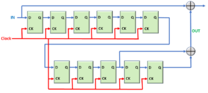
Figure 1, Illustration of the Inverse PN-11 Circuit
How Does this Inverse PN-11 Circuit Work?
This Inverse PN-11 Circuit makes up a big part of our dAIS Detection Circuit (that we also mention in the post on the OTSi/OTUk_A_Sk atomic function).
The user should apply the Recovered OTUk Data and Clock Signal at the IN and Clock inputs of our Inverse PN-11 Circuit, respectively.
If our OTUk data-stream is carrying the OTUk-AIS Maintenance signal (e.g., an Unframed PN-11 signal) and if we are applying this data to the IN input (of our circuit), then our Inverse PN-11 circuit will generate an All-Zeros Pattern at the Node, that I’ve labeled OUT.
I show our Inverse PN-11 Circuit, again, below in Figure 2. However, in this figure, I also highlight these two reference points.
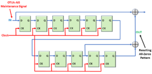
Figure 2, Illustration of the Inverse PN-11 Circuit – with the Locations of the OTUk-AIS Maintenance Signal and the Resulting All-Zeros Pattern Highlighted.
Before we get too excited, we need to recognize that two conditions will cause our Inverse PN-11 circuit to generate an All-Zeros Pattern at the OUT node.
- Our Inverse PN-11 Circuit will generate the All-Zeros pattern at the OUT Node whenever the OTUk-AIS Maintenance Signal is present at the IN input (to this circuit), and
- Our Inverse PN-11 Circuit will also generate the AIl-Zeros pattern (at the OUT Node) whenever someone applies an All-Zeros Pattern at the IN Input.
OTUk-AIS Maintenance Signal or All-Zeros Pattern Signal at the IN input?
Hence, whenever we use the Inverse PN-11 Circuit to check for the OTUk-AIS Maintenance signal, we (of course) need to check the OUT Node (or our Inverse PN-11 Circuit).
However, we also need to check and ensure that we are NOT receiving an All-Zeros pattern at the IN input.
If we are TRULY receiving the OTUk-AIS Maintenance Signal, we will see an All-Zeros pattern at the OUT Node, while the signal at the IN input is NOT an All-Zeros pattern.
I summarize how the Inverse PN-11 Detector circuit works for various signals (at the IN input) below in Table 1.
Table 1, A Truth Table presenting How the Inverse PN-11 Detector Circuit responds to Various Signals (at the IN input)
| IN Input | OUT Node | Comments |
|---|---|---|
| All-Zeros Signal | All-Zeros Signal | An All-Zeros pattern at the IN Input results in an All-Zeros pattern at the OUT Node. No OTUk-AIS. |
| Ordinary OTUk Traffic | Non All-Zeros Pattern Signal | Normal Traffic Situation |
| OTUk-AIS Maintenance Signal | All-Zeros Signal | The Presence of an All-Zeros Signal at the OUT Node, and the Non All-Zeros pattern at the IN input indicates OTUk-AIS. |
Stuck at Home? You Can Become an Expert in OTN Before You Return to Your Office. Click on the Banner Below to Learn More!!!
Corporate Discounts Available for a Short Time!!

Criteria for Declaring the dAIS Defect?
OK, we now have a basic understanding of how the Inverse PN-11 Detector circuit works. We also know what signals to look for to determine if the Inverse PN-11 Circuit detects the OTUk-AIS Maintenance signal.
Let’s now move on to the full criteria for declaring the dAIS defect.
When checking for dAIS, ITU-T G.798 recommends that we continuously monitor both of the signals at the IN input signal and the OUT Node of our Inverse PN-11 Circuit.
ITU-T G.798 goes on to (effectively) state that we should continuously check these signals over a rolling 8192 bit-interval (or sliding window, if you will).
If our Inverse PN-11 circuit detects a set of three (3) consecutive strings each of 8192-bit periods (in length), such that BOTH of the following conditions are TRUE for each of these three 8192 bit-periods, then we MUST declare the dAIS defect condition.
- The number of 1s bits at the OUT Node is less than 256; AND
- the number of 1s bits at the IN Input is 256 or more.
I show an illustration of the dAIS Defect Declaration Criteria below in Figure 3.

Figure 3, Illustration of the dAIS (OTUk-AIS) Defect Declaration Criteria
Criteria for Clearing the dAIS Defect Condition
On the other hand, while we are declaring the dAIS defect, if our Inverse PN-11 circuit detects a set of three (3) consecutive strings, each of 8192-bit periods (in length) such that EITHER of the following conditions is TRUE for each of these three 8192 bit periods, then we MUST clear the dAIS defect condition.
- If the number of 1s bits at the OUT Node is 256 or more, OR
- If the number of 1s bits at the IN input is less than 256 in three consecutive 8192-bit intervals.
I show an illustration of the dAIS Defect Clearance Criteria below in Figure 4.
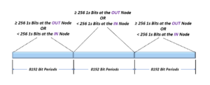
Figure 4, Illustration of the dAIS (OTUk-AIS) Defect Clearance Criteria
What Entities or Atomic Functions declare and clear the dAIS (OTUk-AIS) defect condition?
The OTSi/OTUk_A_Sk function is the only atomic function that contains an Inverse PN-11 Detector circuit. Hence, it is the one atomic function that will declare or clear the OTUk-dAIS Defect condition.
NOTE: For Multi-Lane Applications, the OTSiG/OTUk_A_Sk function does not contain an Inverse PN-11 Detector circuit nor declare or clear the dAIS Defect condition.
If for some reason, an OTL3.4 or OTL4.4 signal were carrying the OTUk-AIS Maintenance Signal (which, again, is an Unframed PN-11 Pattern), then the OTSiG/OTUk_A_Sk function (that is receiving this signal) would instead, continuously declare the dLOFLANE defect condition(*) within each of the 4 or 20 Logical Lanes.
This atomic function would also declare the dLOL defect(*) as well.
NOTE: (*) – Indicates that you need to be a member of THE BEST DARN OTN TRAINING PRESENTATION…PERIOD!! to access these links.
Clueless about OTN? We Can Help!! Click on the Banner Below to Learn More!!
Discounts Available for a Short Time!!

Click on the Image below to See More OTN-Related Posts
