

What is the OTSi/OTUk_A_So Atomic Function?
The expression: OTSi/OTUk_A_So is an abbreviation for the term: Optical Tributary Signal to OTUk Adaptation Source Function.
This blog post will briefly describe the OTSi/OTUk_A_So set of atomic functions.
Changes in Terminology
Before we proceed on with this post, we need to cover some recent changes in terminology. Before the June 2016 Version of ITU-T G.709, the standard documents referred to this particular atomic function as the OCh/OTUk_A_So function.
However, the standards committee has recently decided to change the wording from using the term OCh (for Optical Channel) to OTSi (for Optical Tributary Signal).
For completeness, I will tell you that ITU-T G.959.1 defines the term OTSi as:
“Optical signal that is placed within a network media channel for transport across the optical network. This may consist of a single modulated optical carrier or a group of modulated optical carriers or subcarriers.“.
Therefore, to “speak the same language” as the standard committee, we will call this atomic function the OTSi/OTUk_A_So atomic function.
Likewise, in another post, we will now call (what we used to call the OCh/OTUk_A_Sk function) the OTSi/OTUk_A_Sk function.
I have created another post that provides documentation of the relationships between some old (now obsolete) terms and the new (and approved) ones that our standard committee is currently using.
Clueless about OTN? We Can Help!!! Click on the Banner Below to Learn More!!!
Corporate Discounts Available!!!

The OTSi/OTUk_A_So Function
The OTSi/OTUk_A_So function is any circuit that takes an OTUk data-stream, clock, frame-start, and multi-frame start signals and converts this data into a combined, scrambled data-stream, which (in some cases) contains a FEC (Forward Error Correction) field. This data stream can be readily converted into the optical format (at the output of this function).
ITU-T G.798 states that the system designer can use this function for all OTUk rates (e.g., from OTU1 through OTU4).
However, in most cases, we will typically use the OTSi/OTUk_A_So function for OTU1 and OTU2 applications. We will usually use the OTSiG/OTUk_A_So atomic function for OTU3 and OTU4 applications.
We discuss the OTSiG/OTUk_A_So atomic function in another post.
Figure 1 presents a simple illustration of the OTSi/OTUk_A_So function.

Figure 1, Simple Illustration of the OTSi/OTUk_A_So function.
ITU-T G.798 defines three variants of this particular function. I have listed these variants below in Table 1.
Table 1, List of the ITU-T G.798-specified Variants for the OTSi/OTUk_A_So functions
| Function Name | Description | Comments |
|---|---|---|
| OTSi/OTUk-a_A_So | OTSi to OTUk Adaptation Source Function with ITU-T G.709 Standard FEC | Can be used for OTU1 through OTU4 applications |
| OTSi/OTUk-b_A_So | OTSi to OTUk Adaptation Source Function with No FEC | Cannot be used for OTU4 applications |
| OTSi/OTUk-v_A_So | OTSi to OTUk Adaptation Function with Vendor-Specific FEC | Can be used for OTU1 through OTU4 applications |
Table 1 shows that the OTSi/OTUk-a_A_So and the OTSi/OTUk-v_A_So functions will compute and append some FEC field to the back-end of each outbound OTUk frame.
However, this table also shows that the OTSi/OTUk-b_A_So variant does not generate the FEC field.
Consequently, ITU-T G.798 states that one can use the OTSi/OTUk-a_A_So and OTSi/OTUk-v_A_So functions for OTU1 through OTU4 applications. The standard also recommends that the user NOT use the OTSi/OTUk-b_A_So function for OTU4 applications.
The OTU4 rate requires the use of Forward-Error-Correction.
What Variant will we Discuss Throughout this Post?
Throughout this post, we will be discussing the OTSi/OTUk-a_A_So version of this atomic function.
The OTSi/OTUk-b_A_So and OTSi/OTUk-v_A_So atomic functions do everything that the OTSi/OTUk-a_A_So does, except that the -b variant does NO FEC Encoding and the -v variant does FEC Encoding differently than what I describe here.
So What All Does this Atomic Function Do?
The OTSi/OTUk-a_A_So function will accept the OTUk data-stream, OTUk clock signal, frame-start signal, and multi-frame start signals via the CI_D, CI_CK, CI_FS, and CI_MFS inputs (of this function) respectively, and it will perform the following tasks.
- It will insert the FAS and MFAS fields into the OTUk data stream (coincident with whenever the upstream OTUk_TT_So function asserts the CI_FS and CI_MFS input, respectively).
- This function will compute and append a FEC field to the back-end of each outbound OTUk frame)
- It will scramble this “combined” OTUk data stream (consisting of the FAS, MFAS, and FEC fields)
- This function will then transmit this combined (and scrambled) data stream to external Electrical-to-Optical Conversion circuitry (which will convert our full-blown OTUk signal into the optical format).
Figure 2 illustrates a Unidirectional Connection that shows where the OTSi/OTUk-a_A_So function “fits in” within a system.

Figure 2, Illustration of an STE, transmitting an OTUk signal (over optical fiber) to another STE – the OTSi/OTUk-a_A_So function is highlighted.
Functional Description of this Atomic Function
Let’s take a closer look at this function now.
Figure 3 presents the Functional Block Diagram of the OTSi/OTUk-a_A_So Atomic Function.
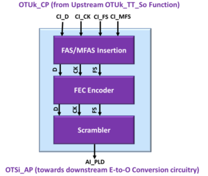
Figure 3, Illustration of the Functional Block Diagram of the OTSi/OTUk-a_A_So Atomic Function
Hence, Figure 3 shows that this function contains the following functional blocks.
- MFAS/FAS Insertion Block
- FEC Encoder Block
- Scrambler Block
I will briefly discuss each of these functional blocks below.
The MFAS/FAS Insertion Block
The MFAS/FAS Insertion block will insert the FAS and MFAS fields into the outbound OTUk data stream each time the upstream OTUk_TT_So function asserts the CI_FS input pin.
Likewise, the MFAS/FAS Insertion block will initialize the MFAS byte-field (to 0x00) within the outbound OTUk-data-stream each time the upstream OTUk_TT_So function asserts the CI_MFS input.
The MFAS/FAS Insertion Block will proceed to increment the contents of the MFAS field within each OTUk frame it generates.
Has Inflation got You Down? Our Price Discount Can Help You Fight Inflation and Help You To Become an Expert on OTN!! Click on the Banner Below to Learn More!!
Corporate Discounts Available!!!
The FEC Encoder Block
The FEC Encoder Block (within the OTSi/OTUk-a_A_So function) will compute the FEC field and append this field to the back-end of each outbound OTUk frame.
ITU-T G.709 recommends that (for a Fully-Compliant OTUk Frame), one uses the Reed Solomon RS(255,239) Code for its Forward-Error Correction scheme.
The standard also recommends that the System Designer use Symbol-Interleaving and that the user place the resulting FEC code into a 4-row x 256-byte column field at the back-end of each outbound OTUk frame.
I show the location (that the FEC Encoder should insert the FEC Code) within the OTUk frame below in Figure 4.
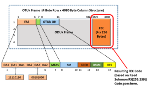
Figure 4, Location of FEC Code (at the back-end of each outbound OTUk frame)
Another post discusses this Forward Error Correction scheme in much greater detail.
Scrambler Block
ITU-T G.709 mandates that we scramble OTUk data before we transmit it over optical fiber.
The standard requires that we do this to ensure that this OTUk signal (that we transmit over optical fiber) has sufficient bit-timing content for Clock and Data Recovery PLLs (Phase-Locked Loops) within the Sink STE (at the remote end).
ITU-T G.709 further states that the Scrambler must operate as a frame synchronous scrambler of sequence length 65,535 (e.g., 216-1), running at the OTUk rate.
Finally, ITU-T G.709 also states that the Scrambler must use the generating polynomial of 1 + x + x3 + x12 + x16.
I show a simple diagram of how one can implement the Scrambler within their OTSi/OTUk-a_A_So function design below in Figure 5.
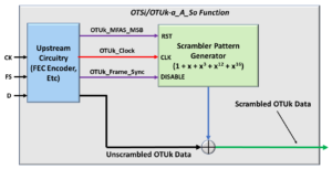
Figure 5, High-Level Block Diagram of the Frame Synchronous Scrambler
I discuss the Scrambler function and requirements in greater detail in another post.
Once the OTSi/OTUk-a_A_So function has scrambled this outbound OTUk data stream, it will transmit it to some Electrical-to-Optical conversion circuitry (which will convert this data stream into the Optical Format) for transmission.
Function Defects
This function does not declare any defect conditions.
Function Consequent Equations
This function does not have any Consequent Action (or Equations).
Pin Description of the OTSi/OTUk-a_A_S0 Function
Table 2 presents a list and description of each of the Input and Output pins of the OTSi/OTUk-a_A_So Function.
Table 2, Pin Description of the OTSi/OTUk-a_A_So Atomic Function
| Signal Name | Type | Description |
|---|---|---|
| OTUk_CP Interface | ||
| CI_D | Input | OTUk Characteristic Information - Data Input: The function user (upstream OTUk_TT_So function) is expected to apply the OTUk data-stream via this input. This OTUk data-stream will contain all of the following portions of the OTUk frame. - OTUk SMOH (Section Monitoring Overhead) data - All remaining OTUk payload data (e.g., the ODUk/OPUk data). NOTE: This data will not include the FAS, MFAS nor FEC fields. All data that the user supplies to this input should be synchronized with the CI_CK input clock signal. NOTE: This OTUk data-stream should be unscrambled. |
| CI_CK | Input | OTUk Characteristic Information - Clock Input: This clock signal will sample all data that the user supplies to the CI_D, CI_FS and CI_MFS inputs. The OTSi/OTUk-a_A_So function will also use this clock signal as its base timing source. |
| CI_FS | Input | OTUk Characteristic Information - Frame Start Input: The upstream OTUk_TT_Sk function will drive this input signal TRUE, coincident to whenever it is supplying the very first bit or byte (of a given OTUk frame) to the CI_D input. The OTSi/OTUk-a_A_So function will insert the FAS field into the outbound OTUk data-stream coincident to whenever the user asserts this input signal. The upstream OTUk_TT_So function is expected to assert this signal once for each OTUk frame period. |
| CI_MFS | Input | OTUk Characteristic Information - Multiframe Start Input: The upstream OTUk_TT_So function will drive this input signal TRUE coincident to whenever it is supplying the very first bit or byte of a given OTUk superframe to the CI_D input. The OTSi/OTUk-a_A_So function will set the MFAS byte to 0x00 coincident to whenever the user asserts this input signal. The upstream OTUk_TT_So function is expected to assert this signal once for each OTUk superframe period, one once every 256 OTUk frame periods. |
| OTSi_AP Interface | ||
| AI_PLD | Output | OTSi Adapted Information - OTSi Payload Output: The OTSi/OTUk-a_A_So function takes all of the data (that the user supplies to the CI_D input pin), along with the FAS, MFAS and FEC data that it has also inserted into this OTUk data-stream. Finally, this function will scramble this data before it outputs all of this data via this output pin. In summary, this signal will contain a full-blown OTUk data-stream (that consists of all of its framing fields and the FEC) and is also scrambled. The system-designer will typically route this data-stream to cicuitry that will convert or modulate this dat into the optical format (for transmission over optical fiber). |
Has Inflation got You Down? Our Price Discount Can Help You Fight Inflation and Help You to Become an Expert on OTN!! Click on the Banner Below to Learn More!!
Discounts Available for a Short Time!!
For More Blog Posts on Optical Transport Networks, please CLICK on the Image Below.
