

What is the OTUk/ODUk_A_Sk Atomic Function?
We formally call the OTUk/ODUk_A_Sk Atomic Function the OTUk to ODUk Adaptation Sink Function.
Introduction
The OTUk/ODUk_A_Sk function performs the exact reverse operation, as does the OTUk/ODUk_A_So function.
NOTE: We extensively discuss the OTUk/ODUk_A_Sk function within Lesson 9 of THE BEST DARN OTN TRAINING PRESENTATION…PERIOD!!!
More specifically, this function will:
- Accept an OTUk signal (from upstream circuitry) and
- Extract (or de-map) out an ODUk signal from this signal.
Figure 1 presents a simple illustration of the OTUk/ODUk_A_Sk function.
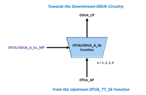
Figure 1, Simple Illustration of the OTUk/ODUk_A_Sk Function
As the OTUk/ODUk_A_Sk function converts an OTUk signal into an ODUk signal, it will terminate, process, and remove the OTUk-SMOH from this incoming OTUk data stream. It will also extract the ODUk signal from this OTUk signal and route it to the downstream ODUk circuitry for further processing.
Please see the post on the ODUk_TT_Sk atomic function for more information on how ITU-T G.798 recommends that we handle and process ODUk signals.
The Interfaces within the OTUk/ODUk_A_Sk Function
Figure 1 shows that this function consists of the following three interfaces.
- OTUk_AP – The OTUk Access Point: This is the interface where the function user supplies the OTUk data to the function. The upstream OTUk_TT_Sk function usually drives the signals within this interface.
- ODUk_CP – The ODUk Connection Point: This is where the function outputs ODUk data, clock, frame, and multi-frame signals (of the extracted ODUk data-stream) towards the ODUk-client circuitry.
- OTUk/ODUk_A_So_MP – The Function Management Point: This interface permits the function user to exercise control and monitor the activity within the OTUk/ODUk_A_Sk function. This interface also allows the ODUk-client to access the APS channel (within the ODUk data stream).
Functional Block Diagram
Figure 2 presents the functional block diagram of the OTUk/ODUk_A_Sk function.

Figure 2, Functional Block Diagram of the OTUk/ODUk_A_Sk Function
This figure shows the upstream equipment (e.g., the OTUk_TT_Sk function), which we typically connect to the OTUk_AP Interface (of the OTUk/ODUk_A_Sk function), will supply the following signals to this function.
- AI_D – OTUk data (with the SMOH)
- AI_CK – The OTUk clock input signal
- AI_FS – The OTUk Frame Start Input signal
- AI_MFS – The OTUk Multi-frame Start Input signal
Clueless about OTN? We Can Help!!! Click on the Banner Below to Learn More!!!
Corporate Discounts Available!!

So What All Does this Atomic Function Do?
The OTUk/ODUk_A_Sk function will perform the following operations on these signals.
It will extract out/de-map the ODUk Data-Stream, the De-Mapping (ODUk) Clock Signal (ODCr), and it will generate the FS (Frame Start) and MFS (Multi-Frame Start) Signals.
The OTUk/ODUk_A_Sk function will de-map out and generate the following signals from the incoming OTUk signal.
- ODUk Data-Stream – The ODUk Data consists of both the ODUk Overhead (PMOH) and the ODUk payload data
- The ODUk Clock – The ODUk Clock Output signal
- ODUk FS – The ODUk Frame Start Output
- ODUk MFS – The ODUk Multi-frame Start Output
Extract out APS (Automatic Protection Switching) Commands from the APS Channel (within the ODUk-PMOH)
Once the OTUk/ODUk_A_Sk function has extracted the ODUk Data (which consists of the ODUk Overhead and Payload data), this function will now give the user access to the APS Channel (which is available via the APS/PCC field within the ODUk Overhead).
This function will route the APS Command information (within APS/PCC Channel) to the CI_APS output.
Transmits Either a Normal ODUk signal or the ODUk-LCK or ODUk-AIS Maintenance Signals downstream
The user can configure the OTUk/ODUk_A_Sk function to either output Normal (an ODUk signal carrying client-information) data or the ODUk-LCK maintenance signal, depending upon what the user does with the MI_AdminState input (to this function).
The user can also configure this function to automatically generate the ODUk-AIS Maintenance signal (instead of the NORMAL signal) whenever upstream circuitry asserts the AI_TSF input (to this function).
Function Defects
The OTUk/ODUk_A_Sk function does not internally declare any defects.
Consequent Actions
ITU-T G.798 presents the following equations for consequent actions within this particular function.
- aSSF <- AI_TSF and (NOT MI_AdminState = LOCKED)
- aAIS <- AI_TSF and (NOT MI_AdminState = LOCKED)
- aSSD <- AI_TSD and (NOT MI_AdminState = LOCKED)
I will discuss each of these consequent action equations below.
aSSF <- AI_TSF and (NOT MI_AdminState = LOCKED)
This equation means two things.
- The function will NOT declare the SSF (Server Signal Failure) condition if the user configures the MI_AdminState input into the LOCKED position.
- The function will declare the SSF condition if the upstream OTUk_TT_Sk function drives the AI_TSF input pin TRUE (and if the user has NOT set the MI_AdminState to the LOCKED position).
NOTE: If the OTUk/ODUk_A_Sk function declares the SSF condition, it will indicate so by asserting the CI_SSF output pin towards downstream circuitry.
The CI_SSF output signal is a crucial signal for Automatic Protection Switching purposes.
aAIS <- AI_TSF and (NOT MI_AdminState = LOCKED)
This equation means two things.
- Suppose the user sets the MI_AdminState input to the LOCKED position. In that case, this function will unconditionally generate and transmit the ODUk-LCK Maintenance Signal (via the CI_D output), regardless of the current state of the AI_TSF input to this function.
- In this case, the ODUk-LCK Maintenance Signal will override and replace the Normal ODUk Signal.
- The OTUk/ODUk_A_Sk function will automatically generate and transmit the ODUk-AIS Maintenance Signal (via the CI_D output signal of this function) if the AI_TSF input pin is set to TRUE (provided that the MI_AdminState input is NOT set to the LOCKED position).
- The ODUk-AIS Maintenance Signal will override the Normal ODUk Signal in this case.
This equation also means that this function will only transmit a NORMAL ODUk signal (carrying client data) if the MI_AdminState input is NOT in the LOCKED position and the AI_TSF input pin is set FALSE.
aSSD <- AI_TSD and (NOT MI_AdminState = LOCKED)
This equation means two things.
- This function will not declare the SSD (Server Signal Degrade) condition if the user configures the MI_AdminState input into the LOCKED position.
- The function will declare the SSD condition if the upstream OTUk_TT_Sk function drives the AI_TSD input pin TRUE (and if the user has NOT set the MI_AdminState to the LOCKED position).
NOTE: If the OTUk/ODUk_A_Sk function declares the SSD condition, it will indicate so by asserting the CI_SSD output pin towards downstream circuitry.
The CI_SSD output signal is a crucial signal for Automatic Protection Switching purposes.
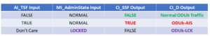
How do the AI_TSF and MI_AdminState input signals affect the CI_SSF and CI_D outputs (from this function)?
The Consequent Equations for aSSF and aAIS all show that the function outputs (via the CI_SSF and CI_D pins) depend upon the state of the AI_TSF and MI_AdminState Inputs, as we offer in Table 1 below.
Table 1, Truth Table of the CI_D and CI_SSF Output Signals, based upon the AI_TSF and MI_AdminState Inputs
Defect Correlations
None for this function.
Performance Monitoring
None
Pin Description
Table 2 presents a list and description of each input and output signal for the OTUk/ODUk_A_Sk function.
Table 2, List and Definition for each Input and Output Signal in the OTUk/ODUk_A_Sk function
| Signal Name | Type | Description |
|---|---|---|
| OTUk_AP Interface | ||
| AI_D | Input | OTUk Adapted Information - OTUk Input: The upstream OTUk_TT_Sk function is expected to apply a bare-bones OTUk data-stream to this input. NOTE: This OTUk data will contain the following fields: - OTUk SMOH data - The contents of the APS/PCC channel (within the ODUk Overhead) and - The rest of the OTUk frame. This OTUk data-stream will not include the FAS, MFAS or FEC fields |
| AI_CK | Input | OTUk Adapted Information - Clock Input This clock signal will sample all data that the user supplies to the AI_D, AI_FS, AI_MFS, AI_TSF and AI_TSD inputs. The OTUk/ODUk_A_Sk function will also use this clock signal as its base timing source. |
| AI_FS | Input | OTUk Adapted Information - Frame Start Input: The upstream OTUk_TT_Sk function will drive this signal TRUE; coincident to whenever it is supplying the very first bit or byte (of a given OTUk frame) to the AI_D input. The upstream OTUk_TT_Sk function is expected to assert this signal once for each OTUk frame period. |
| AI_MFS | Input | OTUk Adapted Information - Multiframe Start Input: The upstream OTUk_TT_Sk function will drive this signal TRUE coincident to whenever it is supplying the very first bit or byte (of a given OTUk Superframe) to the AI_D input. The upstream OTUk_TT_Sk function is expected to assert this signal once for each OTUk superframe period, or once every 256 OTUk frame periods. |
| AI_TSF | Input | OTUk Adapted Information - Trail Signal Fail Indicator The upsteam equipment (e.g., the OTUk_TT_Sk function) will typically assert this input pin whenever it is declaring one (or more) service-affecting defects wit the data that it is ultimately applying to the AI_D input of this function. This signal has a similar role to the AIS signal. Please see the blog post on AIS for more information on this topic. |
| AI_TSD | Input | OTUk Adapted Information - Trail Signal Degrade Indicator Input: The upstream equipment (e.g., the OTUk_TT_Sk function) will typically assert this input whenever it is declaring the dDEG (Signal Degrade) defect with the data that it is ultimately applying to the AI_D input of this function. |
| ODUk_CP Interface | ||
| CI_D | Output | ODUk Characteristic Information - ODUk Data Output: The OTUk/ODUk_A_Sk function will take the ODUk data (that it has de-mapped from the OTUk signal, applied at the AI_D input) and output this data via this output signal. However, if the user commands this function to output the ODUk-LCK Maintenance Signal, then it will do so via this output pin. Finally, this function will also output the ODUk-AIS Maintenance Signal via this output if conditions warrant. |
| CI_CK | Output | ODUk Characteristic Information - Clock Output: As the ODUk_CP Interface outputs data via the CI_D, CI_FS, CI_MFS, CI_APS, CI_SSF and CI_SSD outputs, all of this data will be updated on one of the clock edges of this clock output signal. |
| CI_FS | Output | ODUk Characteristic Information - Frame Start Output: The ODUk_CP interface will pulse this output signal HIGH whenever the ODUk_CP interface outputs the very first bit (or byte) of a new ODUk frame, via the CI_D output. This output signal will pulse HIGH once for each ODUk frame. |
| CI_MFS | Output | ODUk Characteristic Information - Multiframe Start Output: The ODUk_CP Interface will pulse this output signal HIGH whenever the ODUk_CP interface outputs the very first bit (or byte) of a new ODUk Superframe, via the CI_D output. This output signal will pulse HIGH once for each ODUk Superframe (or once each 256 ODUk frames). |
| CI_SSF | Output | ODUk Characteristic Information - Server Signal Failure Indicator Output: One can think of this output pin as a buffered version of the AI_TSF input pin. This function will drive this output pin HIGH anytime the AI_TSF input pin (at the OTUk_AP Interface) is driven HIGH. Conversely, this function will drive this output pin LOW anytime the AI_TSD input pin is driven LOW. |
| CI_SSD | Output | ODUk Characteristic Information - Server Signal Degrade Output: One can think of this output pin as a buffered version of the AI_TSD output pin. This function will drive this output pin HIGH anytime the AI_TSD input pin (at the OTUk_AP Interface) is driven HIGH. Conversely, this function will drive this output pin LOW anytime the AI_TSD input pin is driven LOW. |
| CI_APS | Output | ODUk Characteristic Information - APS Channel Output: The OTUk/ODUk_A_Sk function will extract out the contents of the APS channel (from the incoming ODUk data-stream) and it will output the contents of the APS/PCC channel (as it applies to the APS Level that this OTUk/ODUk_A_Sk function is operating at). |
| OTUk/ODUk_A_Sk_MP Interface | ||
| MI_AdminState | Input | Management Interface - AdminState Input: This input permits the function user to configure the OTUk/ODUk_A_Sk function to output either NORMAL ODUk data, or the ODUk-LCK maintenance signal via the CI_D output of this function. Setting this input pin to the LOCKED state will configure the OTUk/ODUk_A_Sk function to override the NORMAL ODUk data, and the ODUk-AIS maintenance signal with the ODUk-LCK maintenance signal. |
| MI_APS_En | Input | Management Interface - APS Enable Input This input permits the function user to either enable or disable APS/PCC Channel extraction from the incoming ODUk data-stream. Setting this input pin TRUE configures the OTUk/ODUk_A_Sk function to extract the APS Messages from the APS/PCC channel (within the ODUk Overhead of the incoming ODUk data-stream) and output this data via the CI_APS output port. Conversely, setting this input pin FALSE disables APS Message extraction from the incoming ODUk data-stream. |
| MI_APS_LVL | Input | Management Interface - APS Level Input: This input permits the user to specify the APS Level for this instantiation of the OTUk/ODUk_A_Sk function. If the MI_APS_En input is TRUE, then this input pin will select the APS Level (and that portion of the APS/PCC Channel) that this function will output via the CI_APS output. Please see the APS/PCC post on more information about this protocol. If the MI_APS_En input is FALSE, then this input will be ignored. |
Has Inflation got You Down? Our Price Discount Can Help You Fight Inflation and Help You Become an Expert on OTN!! Click on the Banner Below to Learn More!!
Discounts Available for a Short Time!!!
For More Information on OTN Posts in this Blog, click on the Image below.
