

What is Linear Protection Switching?
A Linear Protection-Switching System is a Protection System (or Protection Group) that contains two nodes:
Each of these two nodes is exchanging normal traffic signals, with each other, over a protected network that consists of both the Working Transport entity and the Protect Transport entity.
I show some simple pictures of Linear Protection Switching Systems below in Figures 1, 2, and 3.
The 1+1 Protection-Switching Architecture

Figure 1, Illustration of a Linear Protection Switching System (A 1+1 Protection-Switching System)
In Figure 1, I show a simple illustration of a 1+1 Protection-Switching system, which also presents the bidirectional traffic flow between the Head-End and Tail-End Nodes.
If you want to learn more about the 1+1 Protection-Switching Architecture, check out the post on this topic.
The 1:N Protection-Switching Architecture
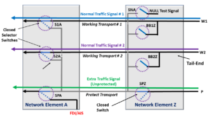
Figure 2, Illustration of a Linear Protection Switching System (A 1:2 Protection-Switching System) – for the East to West Direction

Figure 3, Illustration of a Linear Protection Switching System (A 1:2 Protection-Switching System) – for the West to East Direction
Figures 2 and 3 each present an illustration of a 1:2 (or 1:N) Protection-Switching System.
Please note that the 1:N Protection-Switching Architecture figures are more complicated than that for the 1+1 Protection-Switching Architecture.
Therefore, I needed to show this architecture in the form of two figures.
One figure shows the traffic flowing from West to East, and the other illustrates the traffic flowing from East to West.
If you want to learn more about the 1:2 (or 1:N) Protection-Switching architecture, check out the post on that topic.
In summary, the 1+1 and the 1:N Protection-Switching schemes are Linear-Protection Protection-Switching systems.
Design Variations for Linear Protection-Switching Systems
Linear Protection-Switching systems are available in a wide variety of features. I’ve listed some of these features and their variations below.
Architecture
Switching Type
Operation Type
- Revertive or
- Non-Revertive
APS Protocol – Using the APS/PCC Channel
- No Protocol, or
- Uses the APS Communication Protocol (per ITU-T G.873.1 – for OTN Applications)
Click on any of the links above to learn more about these design variations within a Linear Protection-Switching System.
What about Other Protection-Switching Architectures?
There are other types of Protection Switching systems, which are not Linear, such as Shared-Ring Protection-Switching or Shared-Mesh Protection-Switching.
Please see the relevant posts for more information about those types of Protection-Switching Systems.
Has Inflation got You Down? Our Price Discounts Can Help You Beat Inflation and Help You to Become An Expert on OTN!!! Click on the Banner Below to Learn More!!!
Discount Available for a Short Time!!

Click on the Image Below to see more Protection-Switching related content on this Blog:
