What is Path Terminating Equipment (PTE) for OTN Applications?
Whenever we discuss the OTN Digital Layers (e.g., the OPUk, ODUk, and OTUk layers), we can group Networking Circuits and Equipment into two broad categories.
I will be using these terms throughout various OTN-related posts within this blog. Thus, we must have a strong understanding of these terms.
I have devoted this blog post to discussing PTE (Path Terminating Equipment).
I have devoted another post to STE (Section Terminating Equipment).
You can also find a detailed discussion of PTEs and STEs within Lesson 3 of THE BEST DARN OTN TRAINING PRESENTATION…PERIOD!!! This discussion also describes the differences between PTEs and STEs.
What is the Path?
Before we define the term Path Terminating Equipment (or PTE), we must first explain the word Path as it pertains to an Optical Transport Network (OTN).
For OTN applications, there are two different types of Paths.
- A Non-OTN Client Signal Path (for Non-Multiplexed ODU traffic) and
- An ODUk Server Signal Path (for Multiplexed ODU traffic)
We will define each of these types of Paths below.
Non-OTN Client Signal Path
When transporting a single non-OTN client signal (such as 100GBASE-R) over OTN (e.g., an ODU4/OTU4 signal in this case), the Path begins where the circuitry maps the 100GBASE-R signal into an OPU4 signal.
We can say that the 100GBASE-R signal officially enters the OTN at this point.
This Path ends at the location where the circuitry de-maps the 100GBASE-R signal from the OPU4 signal (and exits the OTN) at the other end of the network.
Figure 1 presents a simple illustration of an OTN that contains some Path Terminating Equipment and some STEs.
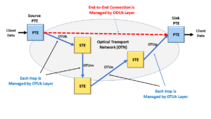
Figure 1, Illustration of both PTE (Path Terminating Equipment) and STE (Section Terminating Equipment) within an Optical Transport Network
In Figure 1, we show that a Source PTE is mapping a 100GBASE-R signal into an OTU4 signal on the left-hand side of Figure 1.
The OTU4 signal transports this 100GBASE-R signal throughout this OTN and through various Section Terminating Equipment blocks labeled STE#1, STE#2, and STE#3.
Afterward, the OTU4 signal finally arrives at the Sink PTE on the right-hand side of Figure 1.
The Sink PTE then de-maps the 100GBASE-R signal from this OTU4 signal.
In the case of Figure 1, the Path (for the 100GBASE-R signal) is that portion of the OTN that exists between the Source PTE (on the left-hand side of Figure 1) and the Sink PTE (on the right-hand side of the same figure).
As this 100GBASE-R signal travels from the Source PTE to the Sink PTE, it will pass through multiple Sections and STEs (we describe in another post). The Path is the route the 100GBASE-R signal takes (through the OTN, via the OTU4 signal).
A Closer Look at the Non-OTN Client SIGNAL Path
Now that we have a basic understanding of what a Path is, let’s take a much closer look at the Path.
Figure 2 presents a more detailed illustration of the Non-OTN Client Signal path within an OTN. This figure also indicates where this Path begins and ends within the OTN.
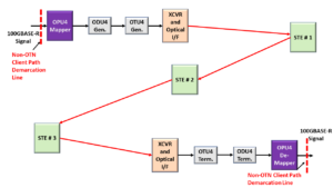
Figure 2, A Closer Look at the Non-OTN Client Signal Path
Once again, Figure 2 shows that the Non-OTN Client Signal Path begins when we map the client signal into an OPU4 signal (and then an ODU4 and OTU4 signal).
In this case, we are mapping a 100GBASE-R client signal into an OPU4 signal at the OPU4 Mapper block.
This figure also shows that this same Path ends where we de-map that same client signal from the OPU4 signal (at the OPU4 De-Mapper block on the lower-right-hand side of Figure 2).
Please note that the diagram in Figure 2 is functionally equivalent to that in Figure 1. In Figure 1, we referred to each signal (between the STE and PTE boxes) as OTU signals. We did not discuss these signals at the OPU4 or ODU4 layers, as shown in Figure 2.
For more details on how we map a 100GBASE-R signal into an OPU4 (and ODU4) server signal, please see Lesson 4 within THE BEST DARN OTN TRAINING PERIOD!!
Let’s now move on to the other type of Path.
Clueless about OTN? We Can Help!!! Click on the Banner Below to Learn More!!!
Corporate Discounts Available!!!

The ODUk Server Signal Path (for Multiplexed ODU Signals)
Another type of OTN Path is the ODUk Server Signal Path.
In the ODUk Server Signal Path, we can map and multiplex multiple lower-speed ODUj tributary signals into a Higher-Speed ODUk server signal (where k > j).
We describe the exact procedure for mapping/multiplexing lower-speed ODUj signals into a higher-speed ODUk signal in other posts.
Figure 3 illustrates a Unidirectional Network that contains both a Non-OTN Client Signal and the ODUk Server Signal set of paths.
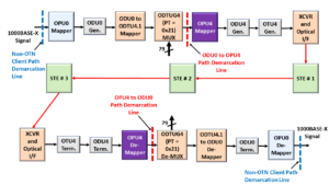
Figure 3, A Closer Look at the ODUk Server Path
NOTE: We described the Non-OTN Client Signal path earlier in this post. Hence, the reader should be familiar with this particular type of Path.
Handling the 1000BASE-X/OPU0/ODU0 Signals
In Figure 3, we have a 1000BASE-X (1GbE) signal that we first map into an OPU0 signal (in the Upper-Left-Hand corner of this figure).
We earlier stated that this point of mapping a non-OTN signal (such as a 1000BASE-X signal) into an OTN signal (e.g., an OPU0 in this case) is the beginning of the Non-OTN Client Signal Path.
Once we’ve mapped this signal into an OPU0, then we will also, in turn, map this OPU0 signal into an ODU0 signal.
Afterward, this ODU0 signal goes through some different processes (that we discuss in detail in other posts) before we map/multiplex this ODU0 tributary signal into an OPU4 signal.
Once we’ve mapped the ODU0 tributary signal (along with 79 other such signals) into an OPU4 signal, this point serves as the entry point for the ODU0 to OPU4/ODU4 Path. We can also call this the ODUk Server Signal Path entry point.
Figure 3 labeled this point as the ODU0 to OPU4 Path Demarcation Line.
This is where this OPU4 signal begins (and serves as the starting point for this particular Path).
Handing the OPU4/ODU4 Server Signal
We then quickly map this OPU4 signal into an ODU4 signal and then (eventually) into an OTU4 signal.
Afterward, we convert this OTU4 signal into an optical signal and transmit it through three additional sets of STEs before arriving at the XCVR and Optical I/F at the Remote Terminal (in the lower-left-hand corner of Figure 3).
The remote terminal converts this signal back into the electrical format and terminates the OTU4 and ODU4 signals.
Finally, the circuitry routes the resulting OPU4 signal to the OPU4 De-Mapper block. The OPU4 De-Mapper block then terminates this OPU4 signal.
This point serves as the OPU4 to the ODU0 Path Demarcation point. This point is where this OPU4 signal (and its Path) ends. We can also say that this is the end of the ODUk Server Signal Path.
NOTE: If you wish to learn more about how we map/multiplex lower speed ODUj tributary signals into an ODU4 Server signal, then you can check out Lesson 5 within THE BEST DARN OTN TRAINING PERIOD!!!
This circuitry will then de-map out the ODU0 tributary signal (of interest) along with as many as 79 other ODU0 tributary signals from this OPU4 signal.
Next, the ODU0 Terminator block will terminate this ODU0 signal and extract the OPU0 signal.
Afterward, it will transmit this data to the OPU0 De-Mapper block.
The OPU0 De-Mapper block will then de-map out the 1000BASE-X (1GbE) client signal from its incoming OPU0 signal.
Once the OPU0 De-Mapper block de-maps the 1000BASE-X signal from the OPU0 signal, this point serves as the Non-OTN Client Path Demarcation point.
In other words, this is the point at which this particular OPU0 signal (and its Path) ends.
How the PTE Operates in the Optical Transport Network
For OTN applications, the ODUk Layer is the protocol layer responsible for managing and monitoring the transmission/reception of data across a Path.
Path Termination Equipment will process data (in the electrical format) by doing many of the following functions:
In the Transmit Direction
- Mapping data (either Non-OTN client data or lower-speed ODUj tributary data) into an OPUk signal and generating the new OPUk signal and overhead.
- Generating the ODUk overhead or the ODUk-PMOH (Path Monitoring Overhead) and attaching the ODUk-PMOH to each outbound OPUk frame.
- Sending this data downstream, the circuitry will either map this signal into another higher-speed ODUk signal or an OTUk frame and precondition it for transmission across the optical fiber.
NOTE: Throughout many of the postings on this blog, we will refer to this ODUk overhead data as the ODUk-PMOH (ODUk-Path Monitoring Overhead) data.
In the Receive Direction
- Receive ODUk data from the upstream OTUk Framer block
- Process and Terminate the ODUk overhead (or ODUk-PMOH). While the PTE is processing the ODUk-PMOH, it will check for the following errors and defects within the incoming ODUk signal.
- Defects or Failures (e.g., dTIM, dPLM, dDEG, dAIS, dOCI, dLCK and PM-BDI)
- Errors (e.g., PM-BIP-8, PM-BEI)
- Terminate the OPUk data stream and de-map either the Non-Client OTN signal or some lower-speed ODUj tributary signals.
- Route the de-mapped data downstream for further processing.
Mapping Data (either Non-OTN client data or lower-speed ODUj tributary data) into an OPUk/ODUk signal
Anytime the PTE maps data (be it non-OTN client data or lower-speed ODUj tributary signals) into an OPUk signal, it will do so by using some of the following mapping procedures.
As the PTE uses one of these mapping procedures to load client data into the OPUk payload, it will load its mapping parameters into the OPUk overhead.
The PTE will also alert the network of the type of traffic that it is transmitting via this OPUk signal by sending the appropriate PSI message via the PSI byte.
Please see the relevant posts for more information on this functionality.
Generating the ODUk Overhead (ODUk-PMOH)
As the PTE receives an OPUk data stream from upstream circuitry, it will precondition all this data for transport through the Path by computing and attaching the ODUk overhead fields to each outbound OPUk frame.
In particular, the PTE will attach some ODUk-PMOH fields to the OPUk frame, which will help it to detect errors and declare and clear certain defect conditions.
Other ODUk overhead fields support maintenance/monitoring features such as Tandem Connection Monitoring, the transport of APS (Automatic Protection Switching) Commands, and other forms of Equipment to Equipment (non-client related) commands and information.
In other posts, we will discuss these topics (e.g., Tandem Connection Monitoring and the APS Channel).
The critical thing to note at this point is that the PTE will use the ODUk-PMOH to monitor the overall health of the entire Path (from the point where it creates the ODUk signal to the end where it terminates this signal).
Figure 4 presents an illustration of the ODUk Overhead that the PTE will use to support the monitoring of this signal as it travels through the Path. NOTE: The ODUk-PMOH is the orange PM field within Figure 4. We will discuss the PMOH in another post.

Figure 4, ODUk Overhead, PMOH, and Payload fields
NOTE: Please see the ODUk Frame post for more information on the ODUk frames and the PMOH fields.
Terminating the OPUk Overhead
After the OTUk signal has been converted into the optical format, received, and converted back into the electrical domain (by the remote terminal), the remote terminal will terminate the OTUk signal (because this equipment is an STE).
Once the STE has terminated OTUk-SMOH, it will route the resulting ODUk signal towards downstream circuitry for further processing.
At this point, the PTE will proceed to terminate the ODUk-PMOH.
As the PTE performs this task, it will check the ODUk-PMOH for the occurrence of bit errors and defects.
The PTE will report the occurrences of such errors and defects to System Management.
Additionally, the PTE will remove all ODUk-PMOH data from this incoming stream (which leaves us with just an OPUk data stream now).
This OPUk data stream is then routed to a De-Mapper block for further processing.
Important Takeaway
The critical takeaway is that the PTE will rely on the ODUk-PMOH data (as shown in Figure 4) to process, manage, and ultimately terminate the ODUk stream.
NOTE: Each ODUk signal (whether it is a lower-speed ODUj tributary signal that we map/multiplex into a higher-speed ODUk server signal) or an ODUk signal (that is carrying a single Non-OTN client signal) will have its ODUk-PMOH data.
This means that PTE (whether it is for transporting a single Non-OTN client signal or one of many lower-speed ODUj signals) will manage and monitor its own respective ODU signal.
I have redrawn Figure 2 to show where the circuitry generates and terminates/monitors the ODU4-PMOH within the Non-OTN Client Path (of 100GBASE-R over OPU4/ODU4).
I have included this figure below in Figure 5.
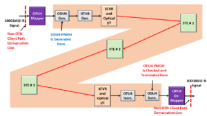
Figure 5, Illustration of the 100GbE to ODU4 Path. (The Entire ODU4 Path is shaded).
NOTE: I have highlighted the locations where the Path Circuitry Generates and Monitors/Terminates the ODU4-PMOH (Non-OTN Client ODU4).
This also means that the circuitry (shown above in Figure 3) would require as many as 81 sets of PTE.
- 80 sets of PTE would be required to monitor each of the 80 ODU0 signals (that we are transporting via the OPU4/ODU4 signal), and
- One additional PTE would be required to monitor the more significant ODU4 signal.
I have also redrawn Figure 3 to show where the circuitry generates and terminates/monitors the ODU0-PMOH within the Non-OTN Client Path (of 1000BASE-X over OPU0/ODU0).
I have included this figure below in Figure 6.
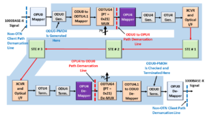
Figure 6, Illustration of the 1GbE to ODU0 -> ODU4 Path. (The entire ODU0 Path is shaded).
NOTE: In Figure 6, I have highlighted the locations where the Path Circuitry Generates and Monitors/Terminates the ODU0-PMOH (Non-OTN Client ODU0).
Finally, I have redrawn Figure 3 (again) to show where the circuitry generates and terminates/monitors the ODU4-PMOH within the ODU0 mapped/multiplexed into OPU4/ODU4 Path.
I have included this figure below in Figure 7.
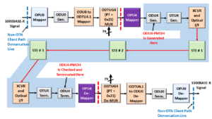
Figure 7, Illustration of the 1GbE to ODU0 -> ODU4 Path. (The Entire ODU4 Path is shaded).
NOTE: I have highlighted the Locations where the Path Circuitry Generates and Monitors/Terminates the ODU4-PMOH (ODU0 Mapped/Multiplexed into OPU4/ODU4).
De-Mapping the Client Signal from the OPUk Payload
Once the OPUk has reached the De-Mapper block, the De-Mapper block will de-map out the client data (be it non-OTN client data or lower-speed ODUj tributary signals) using the mapping parameters that the Source PTE loaded into the OPUk overhead bytes (when it was mapping these clients into the OPUk signal).
This point will be the “end of the line’ for the OPUk frame and overhead.
This circuitry will send the client data downstream for further processing (either by non-OTN system-side circuitry, such as a MAC or other PTE circuitry to handle the lower speed ODUj signals).
Examples of PTE
- Line Cards or Transceivers take (for instance) 100GBASE-R data from a MAC and transport this data over an OTU4 connection (and vice-versa).
- Any equipment that performs ODUj switching and grooming
- ROADMs.
Some Final Comments about the ODUk-PMOH and PTE Equipment.
This post introduced the concept of a Path, Path Terminating Equipment (PTE), and the ODUk-PMOH (Path Monitoring Overhead).
In another post, I describe the Section, Section Terminating Equipment (STE), and the OTUk-SMOH (Section Monitoring Overhead).
STEs will use the OTUk-Layer to manage the data transmission across Sections.
STEs will only generate and process OTUk-SMOH data. They do not process ODUk-PMOH data AT ALL.
Likewise, PTEs will use the ODUk-Layer to manage data transmission across a Path.
PTEs will only generate and process ODUk-PMOH data. They do not process OTUk-SMOH data AT ALL. In most cases, the PTE will not even see the OTUk-SMOH data.
Has Inflation got You Down? Our Price Discounts Can Help You Beat Inflation and Become an Expert on OTN!! Click on the Banner Below to Learn More!!!
Discounts Available for a Short Time!!

For More Information on OTN Posts in this Blog, click on the Image below.

OTN Related Topics within this Blog General Topics Consequent Equations - What are they and How can you use them? ...


