What is the NULL Test Signal for OTN?

This post defines and describes the NULL Signal for OTN (Optical Transport Network) applications.

What is the NULL Test Signal for OTN?

What Exactly is the NULL Test Signal for OTN?

The NULL signal (for OTN) is an OPUk frame with all the following characteristics.

  • The PT (Payload Type) byte-field (within the PSI) is set to the value 0xFD (which indicates that this OPUk frame is transporting the NULL signal).
  • The rest of the 7 RES (Reserved) byte-fields (within the OPUk Overhead) are all set to an All-Zeros pattern (0x00).
  • All the payload bytes (within the OPUk frame) are set in an All-Zeros pattern.

Figure 1 shows a drawing of an OPUk Frame transporting the NULL signal.

OPUk_Frame transporting NULL Signal

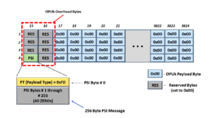
Figure 1, An Illustration of the OPUk frame that is transporting the NULL signal

Any ODUk or OTUk frame that transports an OPUk frame with these characteristics carries the NULL signal.

Additionally, any of the following types of OPUk/ODUk signals can transport the NULL signal:

  • OPU0/ODU0
  • OPU1/ODU1
  • OPU2/ODU2
  • OPU2e/ODU2e
  • OPU3/ODU3
  • OPU4/ODU4
  • OPUflex/ODUflex

Clueless about OTN? We Can Help!! Click on the Banner Below to Learn More!!

Corporate Discounts Available!!!

Where and How would one use the NULL Signal?

ITU-T G.709 defines the NULL signal (for OTN) as a test signal.

Therefore, the System Architect can consider the NULL signal as a tool (in the toolbox) for testing and debugging features available to an OTN system.

Some system applications will transmit the NULL signal via the Protection Transport entity within a 1:1 or 1:n protection switching scheme.  In this case, the user will send the NULL signal instead of either the Extra-Traffic Signal or the ODUk-OCI Maintenance Signal.

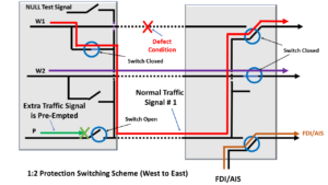
Figure 2 shows a drawing of the 1:2 Protection Switching scheme, in which the user is transporting the NULL signal via the Protection Transport Entity.

1:2 Protection Switching scheme using the NULL Signal

Figure 2, An Illustration of a 1:2 Protection Switching scheme that is transporting the NULL signal via the Protection Transport entity

We can use the NULL signal in any application or situation whenever we need to continuously supply an optical signal (that is carrying timing information) to keep Clock Recovery PLL circuitry (within a downstream Network Element) locked onto the timing signal in the local Network Element.

Simultaneously, the NULL signal will indicate to the downstream Network Element that the connection is working correctly and that there are no defects upstream.

The NULL signal is unlike an AIS signal, which does indicate (to downstream Network Elements) the presence of service-affecting defect conditions upstream.

How Should a System Designer create the NULL Signal for OTN Applications?

The NULL signal (for OTN applications) consists of a fixed pattern.

Therefore, the user can generate OPUk signals (transporting the NULL signal) using a Pattern Generator, which gets its timing from a local clock oscillator.

The System Designer must also ensure that this NULL Signal generator function generates both the OTUk/ODUk Frame and Multi-Frame start indicators.

The Frame Start indicator (FS) should occur every 122,368 clock cycles (or ODUk frame period).

And the Multi-Frame Start indicator (MFS) should occur every 256 frames.

ITU-T G.798 specifies an adaptation function of the name ODUkP/NULL_A_So.

This function is responsible for generating an ODUk signal transporting the NULL signal.

This adaptation function generates the NULL signal from a free-running clock source, which then maps this signal into an OPUk/ODUk frame.

Finally, this function includes the OPUk overhead (e.g., the RES and PT fields) and a default ODUk overhead.

NOTE:  In the case of the default ODUk overhead, this function will set all the ODUk overhead fields to All-Zeros, except for the PM STAT field, which will be set to the value 001 (to indicate a Normal Path Signal).

Figure 3 illustrates the ODUkP/NULL_A_So function from ITU-T G.798.

ODUkP/NULL_A_So function block diagram

Figure 3 illustrates the ODUk/NULL_A_So function from ITU-T G.798.  

What are the Timing (Frequency Accuracy), Jitter, and Wander Requirements for the NULL Signal?

Please see the ODCa (ODU Clock for Asynchronous Mapping) post for the complete Frequency Accuracy and Jitter/Wander requirements of this NULL signal.

Summary

The NULL signal, for OTN applications, is an OPUk frame that has ALL the following characteristics:

  • All the Payload bytes have the value 0x00 (All Zeros).
  • The PT (Payload Type) byte (within the PSI message) has the value of 0xFD (which identifies this particular signal as being the NULL signal)
  • All remaining OPUk overhead fields will be of the value of 0x00 (All Zeros).

Additionally, within the ODUk overhead, the PM STAT field should be set to the value 001.

The NULL signal is a test signal that one can use for test and debugging purposes.

The System Design can also use the NULL signal as a replacement signal for a signal that is unavailable due to user configuration reasons.

Has Inflation got You Down? Our Price Discounts Can Help You Beat Inflation and Help You Become an Expert on OTN!! Click on the Banner Below to Learn More!!

Discounts Available for a Short Time!!

For More Information on OTN Posts in this Blog, click on the Image below.

OTN Related Blog

OTN Related Topics within this Blog

OTN Related Topics within this Blog General Topics Consequent Equations - What are they and How can you use them? ...

What is the Extra Traffic Signal (for APS)?

This post defines and describes the term Extra Traffic Signal, as it is used in a Protection Switching system.


What is the Extra Traffic Signal for APS (Automatic Protection Switching) Purposes?

ITU-T G.808 Defines the Extra Traffic Signal as:
A Traffic signal is carried over the protection transport entity and/or bandwidth when that transport entity/bandwidth is not being used to protect a normal traffic signal, i.e., when the protection transport entity is on standby.  

Whenever the protection transport entity/bandwidth is required to protect or restore the normal traffic on the working transport entity, we will preempt the extra traffic.  

Extra traffic is not protected.

What Does All That Mean?

1:1 and 1:n protection switching schemes often support two types of signals.

The Normal Traffic signal is the high-priority traffic signal that we designed our protection switching scheme to protect.

A Normal Traffic signal will usually travel through a Protection Group (from one Network Element to another) via the Working Transport entity.

What if the Network Declares a Service-Affecting or Signal Degrade Defect Condition with the Working Transport Entity?

However, suppose the Network detects a service-affecting or signal degrade defect within the Working Transport entity.  In that case, the protection group will route the corresponding Normal Traffic Signal through the Protection Transport entity.

The Extra Traffic signal is a lower-priority (and therefore, pre-emptible) traffic signal that will travel through a Protection Group (from one Network Element to another) via the Protection Transport entity whenever it is in standby mode.

In other words, as long as the one (or n) Normal Traffic signals can travel on their Working Transport entities (e.g., the normal condition), then the Extra Traffic signal will use the Protection Transport entity.

The Extra Traffic Gets Dropped

However, suppose the Tail-End circuitry (within the Protection Group) declares a defect condition and asserts the SF or SD indicators.  In that case, the protection scheme will respond to this event by entirely dropping the Extra Traffic signal and routing the Normal Traffic Signal through the Protection-Transport entity in its place.

In some cases, the system operator will transmit the NULL signal, or the ODU-OCI Maintenance signal, via the Protection Transport entity, instead of the Extra-Traffic Signal.

However, unlike the NULL Signal or the ODU-OCI  Maintenance signal, the Extra Traffic Signal can transport user (or client) traffic.  The end customers need to know that their traffic is a lower priority and that Protection-Switching events can preempt (or wipe out) their traffic/service.

In some cases, the Network Service Provider can offer their customers service via an Extra Traffic Signal for a reduced price because this traffic is low priority and preemptible.  

Figure 1 presents a drawing of a 1:2 Protection Switching system.

This figure shows the Normal Traffic signals traveling on the two Working Transport entities.  Normal Traffic Signal # 1 travels along W1 (the Working Transport Entity # 1).  Further, Normal Traffic Signal # 2 travels along W2 (the Working Transport Entity # 2).  

Additionally, this figure shows the Extra Traffic Signal traveling through the Protect Transport entity (P).  

1:2 Protection Switching Architecture - Normal Condition

Figure 1, Drawing of a 1:2 Protection Switching system, with the Extra Traffic Signal highlighted.

How Protection-Switching Preempts the Extra Traffic Signal

If the Network declares a service-affecting defect within one of the Working Transport entities, all the following events will occur.

  • The affected Normal Traffic Signal will now use the Protect Transport entity instead, and
  • The Protection-Switching Network will drop (or preempt) the Extra Traffic Signal.

Figure 2 shows a drawing of the 1:2 Protection Group during protection switching.

In this case, the Network declared a defect within the Working Transport entity associated with Normal Traffic Signal # 1.

Consequently, Normal Traffic Signal # 1 is now using the Protect Transport entity, and the Protection Group is now pre-empting the Extra Traffic signal.

1:2 Protection Switching Architecture - Defect Condition

Figure 2, Drawing of a 1:2 Protection Switching system when a Protection Switch preempts the Extra Traffic signal.

NOTE:  The Extra Traffic signal cannot be a high-priority signal for the following reasons.

  • We do not protect this signal.  If a Service-Affecting defect occurs and we, in turn, lose the Extra-Traffic Signal, our Protection-Switching system will do nothing about it.
  • Even worse, the Extra-Traffic signal is also expendable should one of the Normal Traffic signals need to use the Protect Transport entity.

Has Inflation got You Down? Our Price Discounts Can Help You Beat Inflation and Become an Expert on OTN and Protection-Switching!! Click on the Banner Below to Learn More!!

Discounts Available for a Short Time!!

Click on the Image Below to see more Protection-Switching related content on this Blog:

Protection-Switching Related Blog

Protection-Switching Related Blog Posts

Protection-Switching Related Blog Posts Basic Protection-Switching Terms Head-End (Source Node) Hold-Off Timer Protection-Group Protection-Transport entity Selector Switch Tail-End (Sink Node) ...