What is the ODUk-OCI Maintenance Signal?

This post defines and describes the ODUk-OCI (Open Connection Indication) signal.


What exactly is an ODUk-OCI Maintenance Signal?

OCI is an acronym for Open Connection Indicator.

OTN network equipment will often transmit the ODUk-OCI (Open Connection Indicator) Maintenance Signal to indicate that this particular OTN interface is not connected to an upstream signal (or trail termination source).

In other words, if the system configuration does not connect actual OTN traffic to an OTN interface, then the system will transmit the ODUk-OCI Maintenance signal as a replacement signal through that OTN Interface.

Whenever an OTU Network Equipment (NE) transmits an ODUk-OCI Maintenance signal, it generates and transmits a framed repeating “0110 0110” pattern within the entire ODUk signal.

More specifically, the OTN NE will generate/transmit a series of OTUk frames in which the FAS, MFAS, and OTUk Overhead fields are all valid, and the rest of the OTUk frame (e.g., the ODUk/OPUk portion of the frame) will consist of a repeating 0110 0110 pattern.

The NE will compute the FEC field based on the contents within these OTUk frames.

Figure 1 shows a simple drawing of an OTUk frame transporting the ODUk-OCI Maintenance signal.

ODUk-OCI indicator

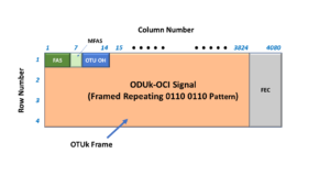
Figure 1, Simple Illustration of an ODUk-OCI Maintenance signal within an OTUk frame

What are the timing/frequency requirements for an ODUk-OCI Maintenance signal?

The OTN NE will need to transmit this indicator at the same nominal bit rate for an ordinary OTUk signal.

Like any other OTUk signal, the OTN NE will need to transmit this data at the nominal bit-rate ±20ppm.

Table 1 presents the nominal bit-rates for the OTUk signals (and, in turn, for the OTUk signal, whenever it is transporting the ODUk-OCI Maintenance Signal) for each value of k.

Table 1, Required Bit Rates for the OTUk Signal – when transporting the ODUk-OCI Maintenance signal.

OTUk Bit Rate and OTUk Frame Period

When would OTN Network Equipment transmit/generate an ODUk-OCI signal?

Earlier, I mentioned that Network Equipment would transmit the ODUk-OCI Maintenance signal via an OTN Interface signal when the system configuration has NOT connected upstream traffic to this OTN interface.

The ODUk-OCI Maintenance signal will replace OTN traffic that was intentionally disconnected from this particular OTN interface.

The ODUk-OCI Maintenance signal is similar to the ODUk-AIS and ODUk-LCK Maintenance signals.  These three signals/indicators serve as replacement signals for actual OTN traffic.

However, the NE will transmit the ODUk-AIS indicator whenever the intended OTN traffic is missing due to a service-affecting defect upstream.

The NE will transmit the ODUk-LCK indicator whenever the OTN traffic is missing because the system operator has administratively locked out that particular OTN interface from all other OTN traffic.

Finally, the NE will transmit the ODUk-OCI maintenance signal whenever the OTN traffic is missing due to user configuration/provisioning (and not because of administrative lock-out).

One practical example of an OTN NE transmitting the ODUk-OCI indicator would be when an OTN traffic signal is not connecting a traffic signal to an OTN interface in an Optical Cross-Connect system.

How does a Receive Terminal detect and declare the dOCI (ODUk-OCI) defect condition?

The Receiving NE (or Sink PTE) that is downstream from the NE, which is transmitting the ODUk-OCI Maintenance signal, will detect and declare the dOCI defect condition whenever it receives a STAT field value of “1, 1, 0” within three (3) consecutive OTUk/ODUk frames.

NOTE:  The STAT field is a 3-bit field that resides within the PM (Path Monitor) byte-field in the ODUk overhead.

This 3-bit field will have the value [1, 1, 0] because the NE overwrites the ODUk overhead with the repeating “0110 0110” pattern whenever it transmits the ODUk-OCI indicator.

Please see the ODUk Frame post for more information about the STAT field.

How does a Sink PTE clear the dOCI defect condition?

The Sink PTE will clear the dOCI defect condition whenever it has accepted a STAT field value of something other than “[1, 1, 0]”.

NOTE:  The Sink PTE should accept a new STAT field value if it receives at least three ODUk frames that contain a consistent STAT field value.

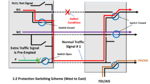
Using the ODUk-OCI Maintenance Signal in Protection-Switching Applications

1:N and ODUk Shared-Ring Protection-Switching Systems will sometimes transport the ODUk-OCI Maintenance Signal through the Protection Transport entity (instead of the Extra-Traffic Signal) whenever we are not using the Protection Transport entity to carry the Normal Traffic Signal.

Has Inflation got You Down? Our Price Discounts Can Help You Beat Inflation and Become an Expert on OTN!! Click on the Banner Below to Learn More!!!

Discount Available for a Short Time!!

For More Information on OTN Posts in this Blog, click on the Image below.

OTN Related Blog

OTN Related Topics within this Blog

OTN Related Topics within this Blog General Topics Consequent Equations - What are they and How can you use them? ...

What is the Extra Traffic Signal (for APS)?

This post defines and describes the term Extra Traffic Signal, as it is used in a Protection Switching system.


What is the Extra Traffic Signal for APS (Automatic Protection Switching) Purposes?

ITU-T G.808 Defines the Extra Traffic Signal as:
A Traffic signal is carried over the protection transport entity and/or bandwidth when that transport entity/bandwidth is not being used to protect a normal traffic signal, i.e., when the protection transport entity is on standby.  

Whenever the protection transport entity/bandwidth is required to protect or restore the normal traffic on the working transport entity, we will preempt the extra traffic.  

Extra traffic is not protected.

What Does All That Mean?

1:1 and 1:n protection switching schemes often support two types of signals.

The Normal Traffic signal is the high-priority traffic signal that we designed our protection switching scheme to protect.

A Normal Traffic signal will usually travel through a Protection Group (from one Network Element to another) via the Working Transport entity.

What if the Network Declares a Service-Affecting or Signal Degrade Defect Condition with the Working Transport Entity?

However, suppose the Network detects a service-affecting or signal degrade defect within the Working Transport entity.  In that case, the protection group will route the corresponding Normal Traffic Signal through the Protection Transport entity.

The Extra Traffic signal is a lower-priority (and therefore, pre-emptible) traffic signal that will travel through a Protection Group (from one Network Element to another) via the Protection Transport entity whenever it is in standby mode.

In other words, as long as the one (or n) Normal Traffic signals can travel on their Working Transport entities (e.g., the normal condition), then the Extra Traffic signal will use the Protection Transport entity.

The Extra Traffic Gets Dropped

However, suppose the Tail-End circuitry (within the Protection Group) declares a defect condition and asserts the SF or SD indicators.  In that case, the protection scheme will respond to this event by entirely dropping the Extra Traffic signal and routing the Normal Traffic Signal through the Protection-Transport entity in its place.

In some cases, the system operator will transmit the NULL signal, or the ODU-OCI Maintenance signal, via the Protection Transport entity, instead of the Extra-Traffic Signal.

However, unlike the NULL Signal or the ODU-OCI  Maintenance signal, the Extra Traffic Signal can transport user (or client) traffic.  The end customers need to know that their traffic is a lower priority and that Protection-Switching events can preempt (or wipe out) their traffic/service.

In some cases, the Network Service Provider can offer their customers service via an Extra Traffic Signal for a reduced price because this traffic is low priority and preemptible.  

Figure 1 presents a drawing of a 1:2 Protection Switching system.

This figure shows the Normal Traffic signals traveling on the two Working Transport entities.  Normal Traffic Signal # 1 travels along W1 (the Working Transport Entity # 1).  Further, Normal Traffic Signal # 2 travels along W2 (the Working Transport Entity # 2).  

Additionally, this figure shows the Extra Traffic Signal traveling through the Protect Transport entity (P).  

1:2 Protection Switching Architecture - Normal Condition

Figure 1, Drawing of a 1:2 Protection Switching system, with the Extra Traffic Signal highlighted.

How Protection-Switching Preempts the Extra Traffic Signal

If the Network declares a service-affecting defect within one of the Working Transport entities, all the following events will occur.

  • The affected Normal Traffic Signal will now use the Protect Transport entity instead, and
  • The Protection-Switching Network will drop (or preempt) the Extra Traffic Signal.

Figure 2 shows a drawing of the 1:2 Protection Group during protection switching.

In this case, the Network declared a defect within the Working Transport entity associated with Normal Traffic Signal # 1.

Consequently, Normal Traffic Signal # 1 is now using the Protect Transport entity, and the Protection Group is now pre-empting the Extra Traffic signal.

1:2 Protection Switching Architecture - Defect Condition

Figure 2, Drawing of a 1:2 Protection Switching system when a Protection Switch preempts the Extra Traffic signal.

NOTE:  The Extra Traffic signal cannot be a high-priority signal for the following reasons.

  • We do not protect this signal.  If a Service-Affecting defect occurs and we, in turn, lose the Extra-Traffic Signal, our Protection-Switching system will do nothing about it.
  • Even worse, the Extra-Traffic signal is also expendable should one of the Normal Traffic signals need to use the Protect Transport entity.

Has Inflation got You Down? Our Price Discounts Can Help You Beat Inflation and Become an Expert on OTN and Protection-Switching!! Click on the Banner Below to Learn More!!

Discounts Available for a Short Time!!

Click on the Image Below to see more Protection-Switching related content on this Blog:

Protection-Switching Related Blog

Protection-Switching Related Blog Posts

Protection-Switching Related Blog Posts Basic Protection-Switching Terms Head-End (Source Node) Hold-Off Timer Protection-Group Protection-Transport entity Selector Switch Tail-End (Sink Node) ...