What is the OPU – Optical Payload Unit?
The OPU (Optical Payload Unit) is that portion of an OTU Frame that transports “payload” or “client-data” throughout the Optical Transport Network.
An OPU is a subset of an ODU (Optical Data Unit) and an OTU (Optical Transport Unit) Frame.
Figure 1 presents an illustration of an OTU Frame and also identifies the location of the OPU frame.

Figure 1, Illustration of an OTU Frame with the OPU Portion (of the Frame) identified.
We will typically give the OPU (just like its larger OTU cousin) a designation such as OPU0, OPU1, OPU2, OPU3, and OPU4, depending upon the “data rate” or the Data Carrying Capacity of this structure.
Table 1 lists the data-carrying capacity for each type of OPU structure.
Table 1, The Data Carrying (Rate) or Capacity of each OPU Structure.
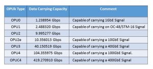
From this point forward, we will refer to the OPU structure as an OPUk (where k can be 0, 1, 2, etc… as presented in Table 1).
NOTE: We describe the ODUflex/OPUflex structure in another post.
The Basic OPUk Frame Format
The OPUk frame consists of two types of bytes:
- Payload Bytes (which we use to transport the Client Data) and
- Overhead Bytes permit OTN equipment to manage the transport of this data.
ITU-T G.709 typically draws the OPUk Payload as a 4-Row x 3808-Byte-Column Structure, yielding 15,232 bytes.
The OPUk Structure also includes 8 Overhead Bytes as well. Hence, the full OPUk Frame (of OPU Payload and Overhead) is a 4-Row x 3810-Byte Column Structure, yielding 15,240 bytes.
Figure 2 presents a Generic Illustration of the OPUk Framing Format with the OPUk Overhead Bytes highlighted.
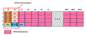
Figure 2, Illustration of a Generic View of the OPUk Structure (e.g., OPUk Payload with the Overhead Bytes highlighted)
Why Do I Call Figure 2 a “Generic Illustration”?
I refer to Figure 2 as a “Generic Illustration” of the OPUk Structure because it includes all possible names/roles for the OPU Overhead bytes.
The names and roles of these OPUk Overhead fields will change depending on which of the following sets of data rates and mapping procedures we are using.
- When operating at the OPU0 through OPU3 rates and using AMP/BMP Mapping
- For the OPU0 through OPU3 rates and using GMP Mapping and
- If running at the OPU4 rate and using GMP Mapping to map/de-map Non-OTN Clients
- For the OPU4 rate and using GMP Mapping to map/de-map lower-speed ODUj tributary signals into/from this OPU4 server signal.
We will briefly illustrate and describe the roles of the OPUk overhead for each of these operating modes.
New Comprehensive OTN Training…Available Now. Click on the Banner Below to Learn More!!!
Discounts Available for a Short Time!!!

The OPUk Frame Format and Overhead for the OPU0 through OPU3 server rates when using BMP/AMP.
If we are supporting the OPU0 through OPU3 rates and if we are using AMP (Asynchronous Mapping Procedure) or BMP (Bit Synchronous Mapping Procedure) to map non-OTN client data or lower-speed ODUj tributary signals into this OPUk server signal, then Figure 3 shows us the OPUk Frame format and overhead that we will be using.
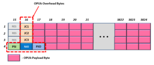
Figure 3, An Illustration of the OPUk Frame Format (and Overhead) for the OPU0 through OPU3 server rates whenever we use AMP or BMP.
Figure 3 shows that the OPUk Frame (for this Operating Mode) has the following overhead bytes:
- JC1 – Justification Control Byte # 1
- JC2 – Justification Control Byte # 2
- JC3 – Justification Control Byte # 3
- PSI – Payload Structure Identifier Byte
- NJO – Negative Justification Opportunity Byte
- PJO – Positive Justification Opportunity Byte
In the case of the OPU0 – OPU3/AMP/BMP modes, the JC1, JC2, JC3, NJO, and PJO bytes will all support the mapping and de-mapping operations of client data into and out of the OPUk signal.
Please see the AMP Post for more details on the roles of these overhead byte fields.
The PSI byte carries information about and identifies the type of client data that the OPUk frame is transporting.
Please see the PSI post for more details about the roles of this byte-field.
NOTE: Figure 3 presents the appropriate OPUk Frame Format and Overhead for all PT = 0x20 applications and some PT = 0x21 applications in which we use AMP.
The OPUk Overhead for the OPU0 through OPU3 rates, when we use GMP to map/de-map client signals into/out of the OPUk server signal.
If we support the OPU0 through OPU3 rates and use GMP (the Generic Mapping Procedure) to map either non-OTN client data or lower speed ODUj tributary signals into this OPUk server signal then Figure 4 shows a drawing of the OPUk frame format that we will be using.

Figure 4, An Illustration of the OPUk Frame Format for the OPU0 through OPU3 rates whenever we use the GMP mapping procedure.
Figure 4 shows that the OPUk Frame (for this Operating Mode) has the following overhead bytes:
- JC1 – Justification Control Byte # 1
- JC2 – Justification Control Byte # 2
- JC3 – Justification Control Byte # 3
- JC4 – Justification Control Byte # 4
- JC5 – Justification Control Byte # 5
- JC6 – Justification Control Byte # 6
- PSI – Payload Structure Identifier byte
In the case of the OPU0 – OPU3/GMP modes, the JC1, JC2, JC3, JC4, JC5, and JC6 bytes will all support the GMP mapping and de-mapping of client data into/from an OPUk signal.
Please see the GMP Procedure for Mapping/De-Mapping Non-OTN Client signal training (in Lesson 4 of THE BEST DARN OTN TRAINING PRESENTATION…PERIOD!!!) on how we use these byte-fields to support the mapping/de-mapping of non-OTN client data into/from OPU frames.
Likewise, please see Lesson 5 (within THE BEST DARN OTN TRAINING PRESENTATION…PERIOD!!!) for information on how we use the GMP Procedure for Mapping/De-Mapping Lower-Speed ODUj Tributary Signals into an ODUk Server signal. This same lesson will also include information on how we use these byte-fields to support the mapping/de-mapping lower-speed ODUj tributary signals into/from the ODUk server signal.
Once again, the PSI byte carries information about and identifies the type of client data that the OPUk frame is transporting.
Please see the PSI post for more details about the roles of this byte-field.
NOTE: Figure 4 presents the appropriate OPUk Frame Format and Overhead for some PT = 0x21 applications.
The OPUk Overhead for OPU4 Applications – Non-OTN Client Case
If we support the OPU4 rate and use GMP to map/de-map a non-OTN client signal into/from this OPU4 signal, then Figure 5 presents an appropriate OPU4 frame format and overhead fields that we will be using. Hence, we would use this OPU frame when GMP mapping a 100GBASE-R signal into an OPU4 signal.

Figure 5, An Illustration of the OPU4 Frame structure whenever we use GMP to map/de-map a non-OTN client.
Figure 5 is very similar to Figure 4, with one exception.
For OPU4 applications, the last eight columns (within the payload) are always a fixed-stuff region that we cannot use to transport data.
Other than that, Figure 5 has the same set of Overhead Bytes as does Figure 4.
The JC1, JC2, JC3, JC4, JC5, and JC6 bytes will all support the GMP mapping and de-mapping client data into/from an OPU4 signal.
Please see the GMP Procedure for Mapping/De-Mapping Non-OTN Client signals lesson (e.g., Lesson 4 within THE BEST DARN OTN TRAINING PRESENTATION…PERIOD!!!) for more information on how we use these byte-fields to support the mapping/de-mapping of non-OTN client data.
The OPUk Overhead for OPU4 Applications – Lower-Speed ODUj Tributary Signal Case
If we are supporting the OPU4 rate and if we are also using GMP to map/de-map lower-speed ODUj tributary signals into/from this OPU4 server signal, then Figure 6 presents a drawing of the appropriate OPU4 frame format and overhead fields that we will be using.

Figure 6, An Illustration of the OPU4 Frame structure whenever we use GMP to map/de-map lower-speed ODUj tributary signals.
Figure 6 is identical to Figure 5, with one exception.
For Non-OTN Client applications, the byte-field in Row 4/Column 16 is labeled “RES” (for RESERVED) and serves no purpose for mapping/de-mapping client data into/from the OPU4 signal.
For Lower-Speed ODUj Tributary Signal Mapping applications, we call this byte-field the OMFI (OPU Multi-Frame Identifier) field.
The JC1, JC2, JC3, JC4, JC5, JC6, and OMFI bytes will all support the GMP mapping and de-mapping of lower-speed ODUj tributary signals into/from an OPU4 signal.
Please see Lesson 5 within THE BEST DARN OTN TRAINING PRESENTATION…PERIOD!!! For more information on how we use these byte-fields to support the mapping/de-mapping of Lower-Speed ODUj Tributary signals into an ODUk Server signal.
Has Inflation got You Down? Our Price Discounts Can Help You Fight Inflation and Become an Expert in OTN? Click Below to Learn More!!
Discounts Available Temporarily

For More Information on OTN Posts in this Blog, click on the image below.

OTN Related Topics within this Blog General Topics Consequent Equations - What are they and How can you use them? ...