What is Ring Switching?

This post briefly describes and defined Ring-Switching within a Shared-Ring Protection-Switching system.


What is Ring-Switching within a Shared-Ring Protection-Switching System?

COMMENT:  Throughout this post, I will use the terms, Ring-Switching and Ring Protection-Switching interchangeably.

A Shared-Ring Protection-Switching system, whether a 2-Fibre/2-Lambda or a 4-Fibre/4-Lambda system, will support Ring Switching.

NOTE:  A 4-Fibre/4-Lambda Shared-Ring Protection-Switching system will also support Span Switching.  However, the 2-Fibre/2-Lambda Protection-Switching System does not support Span-Switching.

Ring-Switching is a Protection-Switching scheme that involves the entire Ring.

Example of Ring-Switching

Just like what I said in the Span-Switching post, the best way to describe Ring-Switching is to show an example of how it works.

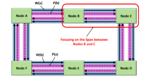
Let’s suppose that we are using a 4-Fibre/4-Lambda Shared-Ring Protection-Switching system.  I present an illustration of a 4-Fibre/4-Lambda Shared-Ring Protection-Switching system below in Figure 1.

4-Fibre/4-Lambda Shared-Ring Protection-Switching System

Figure 1, Illustration of a 4-Fibre/4-Lambda Shared-Ring Protection-Switching

This 4-Fibre/4-Lambda Shared-Ring Protection-Switching system consists of four optical rings (or loops).

  • One Optical Loop is a Working Transport entity in which the data flows in the Clockwise direction.  (e.g., the Blue-Shaded Loop that I’ve labeled W(a)).
  • Another Optical Loop is a Protection Transport entity in which the data flows in the Clockwise Direction (e.g., the Pink-Shaded Loop, which I’ve labeled P(b)).
  • A 3rd Optical Loop is a Protection Transport entity in which the data flows in the Counter-Clockwise Direction.  (e.g., the Pink-Shaded Loop, that I’ve labeled P(a)).
  • And finally, the fourth Optical Loop is a Working Transport entity in which the data flows in the Counter-Clockwise Direction (e.g., the Blue-Shaded Loop, which I’ve labeled W(b)).

Now that we’ve introduced our 4-Fibre/4-Lambda Shared-Ring Protection-Switching system, let’s move on to Ring Protection-Switching.

Defects in the Fiber

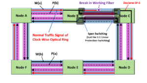
Let’s assume that we are experiencing service-affecting defects within both of the Clockwise-Direction fibers (Working and Protection), between Nodes B and C, as I show below in Figure 2.

Defects in Both Working and Protection Transport Entity - Ring Protection Switching

Figure 2, Illustration of Service-Affecting Defects within both the Working and Protection Transport fibers that were carrying data from Node B to Node C

When this event occurs, Node C will declare the SF defect for the Working Transport entity (SF-W) and the Protection Transport entity (SF-P).  Anytime the Tail-End circuitry (within Node C) declares both the SF-W and the SF-P defect simultaneously, it will also declare the SF-R (Signal Fail-Ring) defect.

Whenever Node C declares the SF-R condition, it will respond to this event by issuing a Ring-Switching request between it and Node B.

Clueless about OTN? We Can Help!!! Click on the Banner Below to Learn More!!!

Corporate Discounts Available!!!

Implementing Ring-Switching

Nodes B and C will exchange APS command information with each other through a protocol (that we call the Shared-Ring Protection-Switching system APS/PCC protocol).

Since the defects (within this example) affect both the Working and Protection Transport entities (in the Span, going from Nodes B and C), these nodes will have to communicate via both Short- and Long-Paths.

If Nodes B and C only respond and perform Ring Protection-Switching, directly in response to the SF-R defect condition (that Node C has declared), then we get the Ring Protection-Switching results we show below.

Ring-Switching in the Defect Direction

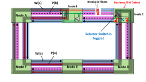
Figure 3, Illustration of Ring Protection-Switching Results (in the Defect Direction)

If you were to study Figure 3, you would see that Ring-Switching works by routing all of the traffic, such that the following is true.

  • That we are routing traffic away from the locations of the defects, and
  • We are still routing traffic through each of the nodes within the Ring.

However, we are not done yet.

ITU-T G.808.2 states that all protection-switching on a Shared-Ring Protection-Switching system must be bidirectional.   Therefore, we must also implement Ring Protection-Switching in the Opposite Direction.  I show this “Opposite-Direction” Ring Protection-Switching below in Figure 4.

Ring-Switching in the Opposite Direction - Opposite from Defect-Direction

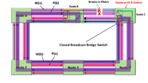
Figure 4, Opposite-Direction Ring Protection-Switching

If I were to combine the Ring Protection-Switching Paths of the Defect-Direction and the Opposite Direction into a single figure, I would get the drawing I present below in Figure 5.

Ring-Switching in Both Directions

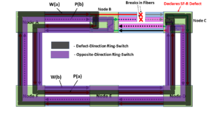
Figure 5, Bidirectional Ring Protection-Switching

Can the User Implement Ring-Switching at other locations in the Shared-Ring Protection-Switching System?

In general, the answer is No.

In our example, Nodes B and C use the Protection-Transport entity resources within much of the Shared-Ring Protection-Switching system.  This fact makes supporting an additional Ring-Switching path very difficult.

That being said, there might be strange scenarios that one can dream up that (temporarily) create two separate ring protection loops.

Why can’t we use Span-Switching whenever we have defects within the Working and Protection Transport entity within a Span?

In the Span-Switching post, we considered a single defect occurring only in the Working-Transport entity (in the span going from Node B to Node C).  Consequently, Node C declared the SF-W (and, in turn) the SF-S (Signal Fail – Span) condition.

In this case, we could use Span-Switching, because we still had a Protection-Transport entity fiber (transmitting data in the same direction as the broken Working Transport entity fiber).  Therefore, we were able to by-pass the single defect by using Span-Switching.

In this post, we have defects in both the Working and Transport entity fibers (in the span going from Node B and Node C).  Since we now have a defect within the Protection-Transport entity, that path (of by-passing the defect in the Working Transport entity) is unavailable to us in this scenario.

Therefore, we have to use a different protection-switching approach.

Has Inflation got You Down? Our Price Discounts Can Help You Beat Inflation and Help You to Become an Expert on OTN!! Click on the Banner Below to Learn More!!

Discounts Available for a Short Time!!!

Click on the Image Below to see more Protection-Switching related content on this Blog:

Protection-Switching Related Blog

Protection-Switching Related Blog Posts

Protection-Switching Related Blog Posts Basic Protection-Switching Terms Head-End (Source Node) Hold-Off Timer Protection-Group Protection-Transport entity Selector Switch Tail-End (Sink Node) ...

What is Span-Switching?

This post defines and describes the term: Span-Switching


What is Span-Switching within a Shared-Ring Protection-Switching System?

A 4-Fibre/4-Lambda Shared-Ring Protection-Switching system will support the two types of Protection-Switching.

NOTE:  A 2-Fibre/2-Lambda Shared-Ring Protection-Switching system will NOT support Span-Switching.  It will only support Ring-Switching.

Span-Switching is a Protection-Switching scheme that only involves a single-Span.

Example of Span-Switching

The best way to describe Span-Switching is to show an example of how it works.

Let’s suppose that we are using a 4-Fibre/4-Lambda Shared-Ring Protection-Switching system.  Additionally, I will focus on the Span between Nodes B and C in this case.

Therefore, in Figure 1, I highlight a 4-Fibre/4-Lambda Shared-Ring Protection-Switching system with the span between Nodes B and C.

Span between Nodes B and C

Figure 1, Illustration of a 4-Fibre/4-Lambda Shared-Ring Protection-Switching system, with the span (between Nodes B and C) highlighted.

If you look closely at the span between Nodes B and C, you will notice that this span contains the following four optical signals.

  • The Clockwise Optical Signal – Working Transport entity (the blue-shaded fiber – with the signal passing through it in the clockwise direction),
  • The Clockwise Optical Signal – Protection Transport entity (the pink-shaded fiber – with the signal moving through it in the clockwise direction),
  • The Counter-Clockwise Optical Signal – Working Transport entity (the blue-shaded fiber – with the signal passing through it in the counter-clockwise direction),
  • The Counter-Clockwise Optical Signal – Protection Transport entity (the pink shaded fiber – with the signal passing through it in the counter-clockwise direction).

Now that we’ve introduced our 4-Fibre/4-Lambda Shared-Ring Protection-Switching system, let’s see some protection-switching.

A Defect in the Fiber

Let’s further assume that we are experiencing a service-affecting defect within the Clockwise-Direction Working Transport entity fiber, as I show below in Figure 2.

SF-S Defect in Span between Nodes B and C - Span Switching

Figure 2, Illustration of a Service-Affecting Defect within the Clockwise Direction Working Transport entity fiber (between Nodes B and C)

Whenever this service-affecting defect occurs (within the Span between Nodes B and C), Node C will declare the SF-S (Signal Fail – Span) defect condition.  Node C will respond to this SF-S defect condition by issuing a Span-Switching request between it and Node B.

Clueless about OTN? We Can Help!!! Click on the Banner Below to Learn More!!

Corporate Discounts Available!!!

Implementing Span-Switching

Nodes B and C will exchange information with each other via a communications protocol (that we called the Shared-Ring Protection-Switching system APS/PCC protocol).

After Nodes B and C have completed this exchange of information (via the APS/PCC protocol), each of these nodes will have executed some protection-switching, such that both Nodes will now be exchanging regular ODUk traffic via the Protection Transport entities (in both directions), rather than using the Defective Working Transport entity (in the Clockwise Direction).

I show the results of this Protection-Switching effort below in Figure 3.

Span-Switching between Nodes B and C

Figure 3, Illustration of Span-Switching, between Nodes B and C

Span-Switching works (in this scenario) because we can use the Protection-Transport entity fiber.  This Protection Transport entity fiber carries traffic in the same direction as the broken Working Transport entity (within the Span, going from Nodes B to C).

Therefore, we can use it to bypass the defect within the Working Transport entity fiber.

NOTE:  All Shared-Ring Protection-Switching will use a 1:1 Protection-Switching Architecture.

Why is this Span-Switching Bidirectional?

Question:

Our 4-Fibre/4-Lambda Shared-Ring Protection-Switching system experienced a single Service-Affecting Defect (within the Working Transport entity of the Clockwise Optical Loop).

Why did we perform Span-Switching in both directions (even for the Counter-Clockwise Optical Loops)?

Answer:

ITU-T G.808.2 states that all Shared-Ring Protection-Switching MUST be Bidirectional.

Therefore, if we are required to perform protection-switching in one direction (to avert a defect condition), we must also complete a similar protection switch in the opposite direction – to make it bidirectional.

Can the User Implement Span-Switching at other locations in the Shared-Ring Protection-Switching System?

In a word, Yes.

In our example, Nodes B and C only use the Protection-Transport entity resources between these two nodes.  We have not taken up any other Protection-Transport entity resources along any remaining spans within the ring.

Therefore, the user can have multiple instances of Span-Switching within a Single Ring.

Has Inflation got You Down? Our Price Discounts Can Help You Beat Inflation and Help You Become an Expert on OTN!! Click on the Banner Below to Learn More!!

Discounts Available for a Short Time!!

Click on the Image Below to see more Protection-Switching related content on this Blog:

Protection-Switching Related Blog

Protection-Switching Related Blog Posts

Protection-Switching Related Blog Posts Basic Protection-Switching Terms Head-End (Source Node) Hold-Off Timer Protection-Group Protection-Transport entity Selector Switch Tail-End (Sink Node) ...

What is a Span (for SRP)?

This post briefly defines and describes the term: Span within a Shared-Ring Protection-Switching system.


What is a Span within a Shared-Ring Protection-Switching System?

In short, a Span is the set of fiber-optic connections between two adjacent nodes within a Shared-Ring Protection-Switching system.

In another post, we defined a Shared-Ring Protection-Switching system as a protection-switching system that contains at least three (3) nodes.

We further stated that each node (within this Shared-Ring Protection-Switching system) is connected to two neighboring nodes.

A span is a set of fiber-optic media that exists between and connects any two neighboring nodes.

I illustrate a Shared-Ring Protection-Switching system, with the Span (between Nodes B and C) highlighted below in Figure 1.

Span between Nodes B and C

Figure 1, Illustration of a 4-Fibre/4-Lambda Shared-Ring Protection-Switching system, with the Span (between Nodes B and C) highlighted.  

What kind of Signals does a Span Transport?

In most Shared-Ring Protection-Switching systems, a span will consist of two or four fibers transporting the following optical signals.

  • Clockwise Direction – Working Transport Entity
  • Clockwise Direction – Protection Transport Entity
  • Counter-Clockwise Direction – Working Transport Entity
  • Counter-Clockwise Direction – Protection Transport Entity

Can a System-Designer implement any sort of Protection-Switching across a Span?

Yes, with a 4-Fibre/4-Lambda Shared-Ring Protection-Switching system, the user can implement Span-Switching as a form of Protection-Switching.

Please see the post on Span-Switching for more information on this topic.

Has Inflation got You Down? Our Price Discounts Can Help You Beat Inflation and Help You Become an Expert on OTN!! Click on the Banner Below to Learn More!!

Discounts Available for a Short Time!!

Click on the Image Below to see more Protection-Switching related content on this Blog:

Protection-Switching Related Blog

Protection-Switching Related Blog Posts

Protection-Switching Related Blog Posts Basic Protection-Switching Terms Head-End (Source Node) Hold-Off Timer Protection-Group Protection-Transport entity Selector Switch Tail-End (Sink Node) ...

Shared-Ring Protection Switching

This post briefly defines the term: Shared-Ring Protection-Switching


What is Shared-Ring Protection Switching?

A Shared-Ring Protection Switching system is a Protection System that contains at least three (3) Nodes.

Each Node within this Shared-Ring Protection-Switching System (or Ring) is connected to two neighboring nodes.

I show an illustration of a Shared-Ring Protection-Switching System below in Figure 1.

4-Fibre/4-Lambda Shared-Ring Protection-Switching System

Figure 1, Illustration of a Shared-Ring Protection-Switching System

Figure 1 presents a shared-ring protection-switching system that consists of six (6) nodes that are each connected to a shared ring that contains four (4) Optical loops (or rings).

Some optical rings carry traffic that flows in the clockwise direction (through each node).  Other rings carry traffic that flows in the counter-clockwise direction.

In Figure 1, I have labeled some of these optical loops as “Working” or Working Transport Entity loops and others as “Protect” or Protection Transport Entity loops.

What are the Nodes within a Shared-Ring Protection-Switching System?

Each node (on the Shared-Ring Protection-Switching system) is an electrical/optical system that functions similarly to an Add-Drop-MUX.

Some data traveling on an optical loop (within the ring) will pass through these nodes.  These Nodes also can add in and drop-out some of the data traveling on these loops.

I show the Add-, Drop- and Pass-Through capability of these Nodes below in Figure 2.

Add-Drop MUX features of Nodes in Shared-Ring Protection-Switching

Figure 2, Illustration of the Add-, Drop- and Pass-Through capabilities of a given node, sitting on the shared-ring.  

It is also important to note that each Node can function as either a Source (or Head-End) Node, a Sink (or Tail-End) Node, or both.

Types of Shared-Ring Protection-Switching Systems

ITU-T G.873.2 defines the following two types of Shared-Ring Protection-Switching systems.

  • The 2-Fibre/2-Lambda Shared-Ring Protection-Switching system, and
  • The 4-Fibre/4-Lambda Shared-Ring Protection-Switching system.

Please click on the links above to learn more about these Shared-Ring Protection-Switching systems.

Types of Protection-Switching within a Shared-Ring Protection-Switching System

The Shared-Ring Protection-Switching system can support both the following kinds of Protection-Switching.

Click on the above links to learn more about these types of Protection-Switching within a Shared-Ring Protection-Switching system.

Design Variations for Shared-Ring Protection-Switching Systems

Shared-Ring Protection-Switching systems are available in a wide variety of features.  I’ve listed some of these features and their possible variations below.

Shared-Ring Protection-Switching Types

  • 2-Fibre/2-Lambda Shared-Ring Protection-Switching systems
  • 4-Fibre/4-Lambda Shared-Ring Protection-Switching systems.

Architecture Type

All Shared-Ring Protection-Switching is of the 1:N Protection-Switching Architecture.

Switching Type

All Shared-Ring Protection-Switching is Bidirectional.

Operation Type

All Shared-Ring Protection-Switching systems use Revertive Operation.

APS Protocol – Using the APS/PCC Channel

All Shared-Ring Protection-Switching systems use the APS Protocol.

What about other types of Protection-Switching?

Other types of Protection-Switching Systems are not Shared-Ring, such as Linear or Shared-Mesh Protection-Switching.

Has Inflation got You Down? Our Price Discounts Can Help You Beat Inflation and Become an Expert on OTN!! Click on the Banner Below to Learn More!!

Discounts Available for a Short Time!!!

Please Click on the Image below to See More Protection-Switching posts within this Blog.

OTN Related Blog

OTN Related Topics within this Blog

OTN Related Topics within this Blog General Topics Consequent Equations - What are they and How can you use them? ...