

What is the ODTU4.1 Frame/Structure? And When do We use it?
Introduction
The term, ODTU4.1, is an acronym for Optical Data Tributary Unit 4.1.
A Mapper circuit will use this structure whenever mapping and multiplexing anywhere between 1 and 80 ODU0 tributary signals into an OPU4/ODU4 server signal.
We will discuss the following topics within this blog post.
- What does the term ODTU4.1 mean?
- A description/definition of the ODTU4.1 frame/structure.
- How do we use the ODTU4.1 structure when mapping/multiplexing multiple lower-speed ODU0 tributary signals into an OPU4 server signal?
- What is the timing/frequency relationship between each ODTU4.1 signal, and
- What is the timing/frequency relationship between each ODTU4.1 signal and the outbound OPU4 frame data?
What is the meaning of the term ODTU4.1?
The numeral 4 (within the expression ODTU4.1) reflects that we use this structure to map data into an OPU4/ODU4 server signal.
The numeral 1 (again, within the expression ODTU4.1) reflects that this structure transports a single ODU0 signal (which contains only 1 (one) 1.25Gbps-unit of bandwidth).
Therefore, the ODTU4.1 structure only transports 1 (one) 1.25Gbps-unit (or tributary-slot) of bandwidth as we map/multiplex this data into an OPU4/ODU4 server signal.
NOTE: I have extensively discussed how we map 80 ODU0 tributary signals into an ODU4 server signal within Lesson 5/ODU4 of THE BEST DARN OTN TRAINING PRESENTATION…PERIOD!!!
There are other similar structures, such as the ODTU4.2, ODTU4.8, ODTU4.31, and ODTU4.ts frames, that we will use to map an ODU1 (2 time-slots), ODU2/2e (8 time-slots), ODU3 (31 time-slots) and ODUflex (ts time-slots) into an OPU4 signal, respectively.
We will discuss each of these structures in other posts.
When do we use the ODTU4.1 structure?
We use these structures when mapping and multiplexing from 1 to 80 lower-speed ODU0 tributary signals into an OPU4/ODU4 server signal.
ITU-T G.709 states that whenever we map/multiplex some ODU0s into an OPU4/ODU4 signal, then we need to do this by executing the following four-step process.
- Convert each ODU0 signal into an Extended ODU0 signal.
- GMP map each ODU0 signal into its ODTU4.1 structure/signal, and
- Byte-Wise Multiplex as many as 80 ODTU4.1 signals together and then
- Load this data into the OPU4 Payload area.
ITU-T G.709 presents a series of figures on mapping/multiplex lower-speed ODUj tributary signals into a higher-speed OPUk server signal (e.g., k > j).
The standard presents the following figure on how to map/multiplex ODU0 signals into an OPU4.

Figure 1, Illustration of the ITU-T G.709 Drawing on how to Map/Multiplex up to 80 ODU0s signals into an OPU4 signal.
I (more or less) copied Figure 1 straight out of ITU-T G.709.
I added some additional text to explain this figure and ITU-T G.709’s instructions.
Figure 1 states that we must first map a single “Extended ODU0 signal” into a single ODTU4.1 signal using GMP (Generic Mapping Procedure).
What Do We Mean by an Extended ODU0 Signal?
Before we can begin the process of mapping/multiplexing any ODU0 tributary signals into an OPU4/ODU4 server signal, we must first convert each of these ODU0 signals into an Extended ODU0 signal.
This means we need to take an ODU0 frame and then “extend it” by attaching the FAS and MFAS fields to this frame, as shown below in Figure 2.
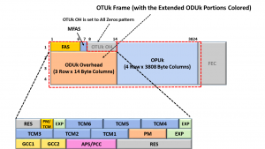
Figure 2, Illustration of the Extended ODU0 Framing Format
We attach the FAS and MFAS fields to each of these ODU0 frames so that the Sink PTE circuitry (at the remote end of the fiber link) can locate the boundaries of ODU0 frames as it de-maps this data from the ODTU4.1 structures.
Please see the OTU Post for more information on the FAS and MFAS fields.
Please also note that (as we include the FAS and MFAS fields within the ODU0), we fill in the rest of the OTUk Overhead to an all-zeroes pattern, and we don’t append the FEC to the back-end of the ODU0 frame.
Mapping the Extended ODU0 signals into the ODTU4.1 Signal/Structure
Once we have converted each of the ODU0 signals into Extended ODU0 signals, we will proceed to GMP map this data into the ODTU4.1 signal/structure.
After performing this mapping step, we will (from here on) be working with ODTU4.1 signals (instead of ODU0 signals) as we load this data into an OPU4/ODU4 frame structure and transport it across an optical link.
These ODU0s will remain embedded within this ODTU4.1 data stream until some “ODTU4.1 to ODU0 De-Mapper” circuit de-maps/extracts the ODU0 signals from the ODTU4.1 signals.
If we are mapping/multiplexing 80 ODU0 signals into an OPU4 signal, then we will map 80 ODU0 signals into each of their own 80 ODTU4.1 signals in parallel.
And we will then have 80 separate ODTU4.1 signals to process and manipulate.
Figure 4 (further down in this post) illustrates some “Mapping circuitry” that maps 80 ODU0 signals into 80 ODTU4.1 signals in parallel.
Byte-Wise Multiplexing the ODTU4.1 Data into the ODTUG4 Structure
Next, Figure 1 states that we must byte-wise multiplex each of the 80 ODTU4.1 signals into a single ODTUG4 data stream.
And finally, we should then map (or insert) this ODTUG4 data stream into the OPU4/ODU4 server payload.
What does the ODTU4.1 Structure Look Like?
Figure 3 presents an illustration of the ODTU4.1 Framing Format.

Figure 3, Illustration of the ODTU4.1 Frame Format
This figure shows that the ODTU4.1 Frame consists of two different sections.
- The ODTU4.1 payload area and
- The ODTU4.1 overhead area
Figure 3 also shows that the ODTU4.1 payload is a 160 Row x 95 Byte Column structure. This figure also shows that the ODTU4.1 frame comprises 6 bytes of overhead.
Please note that 160 Rows x 95 Byte Columns = 15,200 Bytes.
This means that the payload portion of each ODTU4.1 frame will carry 15,200 bytes (the exact number of payload bytes each OPU4 frame takes).
What kind of data resides within the ODTU4.1 Payload?
In short, the ODTU4.1 Payload will contain the contents of its respective Extended ODU0 signal.
Whenever we are GMP mapping an Extended ODU0 signal into an ODTU4.1 signal, we will load the entire Extended ODU0 data stream (e.g., ODU0 overhead, FAS field, and payload data) into the ODTU4.1 payload.
We will load this data into the ODTU4.1 payload in the standard transmission order.
What kind of data resides within the ODTU4.1 Overhead?
When the Mapper circuitry GMP maps the Extended ODU0 tributary signal into the ODTU4.1 structure, it will compute and generate some GMP parameters (for this particular mapping operation).
The Mapper circuitry will compute these GMP parameters based upon the exact bit rates of the Extended ODU0 signal and that on the ODTU4.1 (Server) signal.
The Mapper circuitry will then load this GMP mapping data into the JC1 through JC6 fields (within the ODTU4.1 overhead), just as a GMP mapper would for any client signal.
This set of JC1 through JC6 fields serves the same roles as the JC1 through JC6 fields (within an OPUk structure) whenever we use GMP mapping.
How do we transport the ODTU4.1 Overhead and Payload data across the Optical Link (within an OTN)?
Please see the OMFI Post for details.
Are all the ODTU4.1 signals both frame and byte-synchronous with each other whenever we map this data into the OPU4 payload?
In short, the answer is “Yes.”
The ODTU4.1 frames and signals must have the following timing/synchronization characteristics.
- Each of the 80 ODTU4.1 signals must be bit-synchronous with each other.
- These ODTU4.1 signals must also be bit-synchronous with the outbound OPU4/ODU4 data stream.
- Each of the 80 ODTU4.1 signals must be frame-synchronous with each other, and
- All 80 ODTU4.1 signals must be frame synchronous with the 80 OPU4 Frame Superframe they will eventually be multiplexed into.
We will discuss these characteristics (of the ODTU4.1 signals) below.
BUT FIRST – What about the timing and requirements of the ODU0 tributary signals?
Each ODU0 tributary signal (that we are mapping into an OPU4/ODU4 server signal) can be utterly asynchronous to each other.
Additionally, the only absolute timing requirement for the ODU0 signals is that they have to comply with the Frequency Tolerance requirements per ITU-T G.709.
There is also no requirement that these 80 ODU0 tributary signals be frame-aligned with each other either.
However, once the ODU0 signals are each GMP mapped into their ODTU4.1 signal, then each of the ODTU4.1 signals MUST be both byte- and frame-synchronous to each other.
Each of these ODTU4.1 signals must also be bit-synchronous with the outbound OPU4/ODU4 server signal.
Additionally, each of these ODTU4.1 frames must be aligned with the 80 OPU4 frame Superframe (that they will eventually be a part of).
GMP mapping addresses the timing differences between each of the individual ODU0 tributary signals as they transition from the “ODU0 tributary signal time domains” to the “ODTU4.1/OPU4 Time Domain”.
All of this means that the ODU0 to OPU4 Mapper Circuit must ensure that “Byte 1” (the very first payload byte) within each of the 80 ODTU4.1 frames are all being applied to the “ODTU4.1 Byte MUX” simultaneously.
Let’s focus on these points in greater detail.
ODTU4.1 Signals being Bit-Synchronous with each other
Figure 4 illustrates an ODU0 tributary signal to OPU4 Mapper circuit.
This figure presents 80 sets of “ODU0 Frame Extender/ODU0 to ODTU4.1 Mapper” blocks.
Each block is responsible for GMP mapping its ODU0 signal into an ODTU4.1 Data Signal.

Figure 4, Illustration of an ODU0 tributary signal to OPU4 Mapper Circuit
Figure 4 also shows that a single clock source (e.g., ODTU4.1 and OPU4 Clock Source) will function as the timing source for each of the 80 ODU0 Frame Extender/ODU0 to ODTU4.1 Mapper blocks.
This means that each of the resulting ODTU4.1 signals will be generated based on and synchronized with a common clock source (e.g., the ODTU4.1 and OPU4 Clock Source, in this case).
The OPU4 Output signal will also use the ODTU4.1 and OPU4 Clock Source as its timing source.
ODTU4.1 Signals are Byte-Aligned with Each Other
Figure 5 illustrates an abbreviated byte stream for each of the 80 ODTU4.1 payload signals.

Figure 5, Illustration of the Byte Streams for each of the 80 ODTU4.1 Signals (output from the ODU0 Frame Extender/ODU0 to ODTU4.1 Mapper block in Figure 4).
This figure shows that each ODU0 Frame Extenders/ODU0 to ODTU4.1 Mapper circuit must simultaneously generate and transmit the first payload byte of their ODTU4.1 frame.
Likewise, each ODU0 Frame Extender/ODU0 to ODTU4.1 Mapper circuits must all generate and transmit the very second payload byte of their ODTU4.1 frame simultaneously, and so on.
All 80 of these byte streams will then be routed to downstream circuitry, which will byte-multiplex and map this data into the OPU4 payload, as shown below in Figure 6.

Figure 6, Simple Illustration of Circuitry Byte-Wise Multiplexing Each (of 80) ODTU4.1 Signals into an OPU4 Payload.
ODTU4.1 Signals MUST be Frame Aligned to the 80 OPU4 Frame Superframe
In the OMFI post, we mentioned that we would ultimately map and multiplex each of the ODTU4.1 signals into an 80 OPU4 Frame Superframe.
Figure 7 illustrates an 80 OPU4 frame Superframe we created by byte-wise multiplexing these 80 ODTU4.1 data streams together.

Figure 7, Illustration of an 80 OPU4 frame Superframe.
Looking at Row 1, Byte-Column 17 within OPU4 Frame # 1, you will see that we have designated this byte-field as “1-1“.
This designation means that this byte originated from ODTU4.1 Signal # 1 and is the very first byte (e.g., byte # 1) within that particular ODTU4.1 frame.
Likewise, we designated the next byte-field (to the right) as “2-1“.
This means that this byte originated from ODTU4.1 Signal # 2 and that it is the very first byte within that particular ODTU4.1 frame, and so on.
Figure 6 also shows that the very first payload byte (within the 80 OPU4 frame Superframe) is the very first payload byte (within an ODTU4.1 frame) that originates from ODTU4.1 Signal # 1 (e.g., byte-field “1-1“).
This figure also shows that the next 79 bytes (within this OPU4 frame) are the very first bytes (within each of their ODTU4.1 frames) originating from ODTU4.1 Signal # 2 through ODTU4.1 # 80.
We have designated the next 79 bytes as “2-1“, “3-1“, and so on, all the way to “80-1“.
This figure reinforces the fact that each of the ODTU4.1 streams must also be frame-aligned with each outbound 80 OPU4 frame Superframe.
To better appreciate these concepts, I strongly recommend you check out this portion of Lesson 5 within THE BEST DARN OTN TRAINING..PERIOD course.
Has Inflation got You Down? Our Price Discounts Can Help You Fight Inflation and Help You Become an Expert on OTN!! Click on the Banner Below to Learn More!!!
Discounts Available for a Short Time!!!

For More Information on OTN Posts in this Blog, click on the Image below.
