What is the OTUk-SMOH?

This blog post brief defines the term “Section Monitoring Overhead” (SMOH) for OTN Applications.

What Exactly is the OTUk-SMOH (Section Monitoring Overhead)?

Throughout much of this Blog, whenever I discuss Defects or Errors at the OTUk Layer, I usually mention the expression – OTUk-SMOH.

We have also referred to this same field as the Section Monitoring Overhead or SMOH.  Each term means the same things; I can use them interchangeably in this blog post.  

What exactly is the OTUk-SMOH?

SMOH is an abbreviation for Section Monitoring Overhead.

Figure 1 presents the location of the Section Monitoring (SM) Overhead within the OTU Frame.  
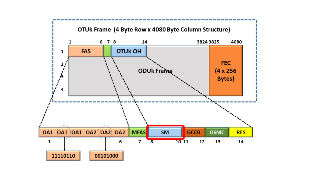
OTUk Framing Format - Identifying Section Monitoring field

Figure 1, Illustration of the OTU Overhead (within an OTU Frame) – with the Section Monitoring Overhead (or SM) Highlighted.

The SM field (or the Section Monitoring Overhead) is a three-byte field. If I were to take that SM field and zoom in on it (to take a closer look), I would have the image below in Figure 2.
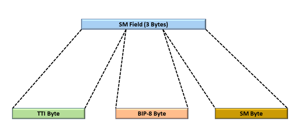
Byte-Level View of the Section Monitoring Field

Figure 2, Close-Up Look at the SM (or Section Monitoring) field.

Figure 2 shows that the SM field consists of 3-byte fields.

  • TTI Byte-field
  • BIP-8 Byte field and
  • the SM Byte field.

What Are These Byte-Fields Within the SMOH?

Let’s go through and define these byte-fields and the role that they take in Section-Monitoring and Management.

What is the TTI Byte field?

I present an illustration of the SM field with the TTI Byte field Highlighted in Figure 3.
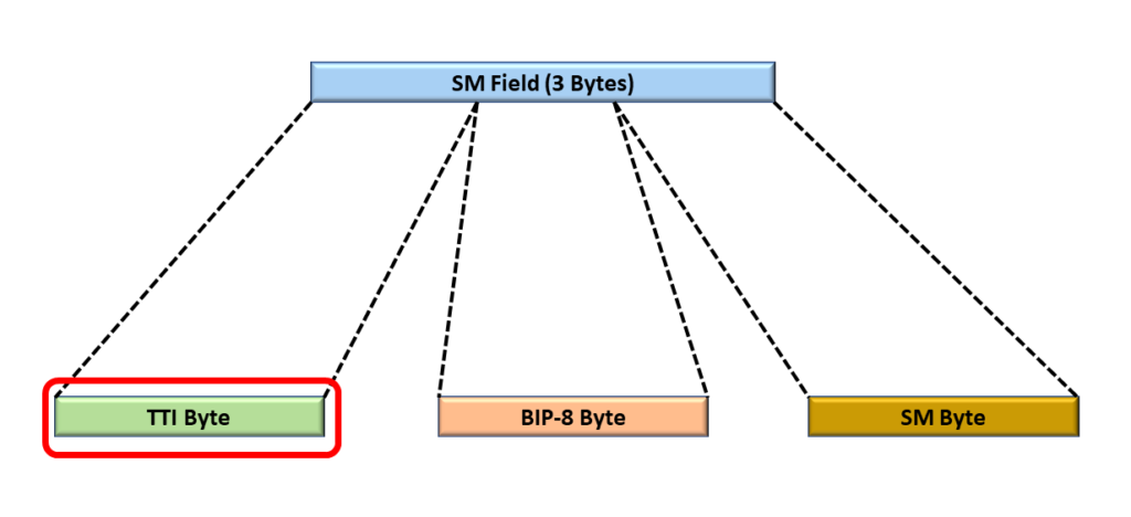
Section Monitoring Field with the TTI (Trail Trace Identifier) Byte-field highlighted

Figure 3, Illustration of the SM Field with the TTI Byte Highlighted

First, “TTI Byte” means Trail Trace Identifier Byte. The purpose of the TTI byte (within the OTUk-SMOH) is to transport the Trail-Trace Identifier Messages from a Source STE to a Sink STE. I show an illustration of the Source STE (STE # 1) transporting the TTI Message to the Sink STE (STE # 2) in Figure 4.

STE transporting a TTI Message to another STE

Figure 4, Illustration of a Network Consisting of an STE transmitting the TTI Message to another STE.

Figure 4 illustrates a network that consists of two (2) pieces of equipment:

  • STE # 1, and
  • STE # 2

I will briefly define and elaborate on these pieces of equipment.

STE # 1

This piece of equipment accepts an OTU4 signal (as an input) from the left-hand side (of the figure) and ultimately outputs an OTU4 single (at the other end of this equipment) out to STE # 2

STE # 2

This piece of equipment accepts an OTU4 signal (as an input) from STE # 1 and ultimately outputs an OTU4 signal (at the other end of this equipment) out to some off-page STE.

What is the TTI Message?

Without going into the details of the TTI Message (and what it means), we will, for now, say that this is a 64-byte message (16-byte SAPI, 16-byte DAPI, and 32 bytes Operator Specific) that uniquely identifies a particular STE (Section Terminating Equipment). Figure 5 presents the byte format of the TTI Message.

Byte Format of the SM-TTI Message - Showing Synchronization between TTI Message and the MFAS Byte

Figure 5, Illustration of the Byte Format of the TTI Message

In this figure, we show that the TTI Message is a 64-byte message that:

  • Consists of 16 bytes for the SAPI (Source Access Point Identifier)
  • 16 bytes for the DAPI (Destination Access Point Identifier), and
  • 32 bytes for the Operator Specific field.

I will define the SAPI and the DAPI in another post. Another point I will make in Figure 5 is that the transmission of TTI Messages is always synchronized with the MFAS byte-field.

For this blog post, I will say that a given STE (STE # 1 in this case) will use the 64-byte TTI Message to repeatedly identify itself to the other STE (STE # 2). STE # 1 will continually transmit these TTI messages to STE # 2. STE # 2 will ensure that it consistently receives an expected (and correct) TTI Message. In other words, STE # 2 will use these TTI Messages to check and verify that it is connected to the correct STE (STE # 1).

How Do We Use the TTI Bytes to Transport the TTI Messages?

Figure 5 shows that there are 64 bytes within each TTI Message. However, Figure 3 shows only one TTI byte within the SM field (hence, only one TTI byte within an entire OTU frame). Therefore, transporting a single 64-byte TTI message over an OTU Section requires that we transport 1 TTI byte at a time over a set of 64 OTU frames.

Further, Figure 5 shows that we will synchronize our transmission of these TTI bytes with the MFAS byte.

For example, whenever the 6-LSBs of the MFAS is set to [0, 0, 0, 0, 0, 0], then we will transport the very first TTI byte of the 64-byte TTI Message. Whenever the 6-LSBs of MFAS are set to [0, 0, 0, 0, 0, 1], then we will transport the second TTI byte of the 64-byte TTI message, and so on.

The Receiving STE (STE # 2) in Figure 4 will use this relationship between the LSBs of the MFAS byte to interpret the data it receives from the Transmitting STE (STE# 1) in this case.

If the Receiving STE receives an erred (or unexpected) value for the TTI Message, then that STE can declare the dTIM (Trail-Trace Identifier Mismatch) defect. We will discuss exactly how an STE declares and clears the dTIM defect in another post.

Clueless About OTN? We Can Help! Click on the Banner Below to Learn More!

Discounts Available for a Short Time

What is the SM-BIP-8 Byte-Field?

I present an illustration of the SM field with the BIP-8 Byte-field Highlighted in Figure 6.
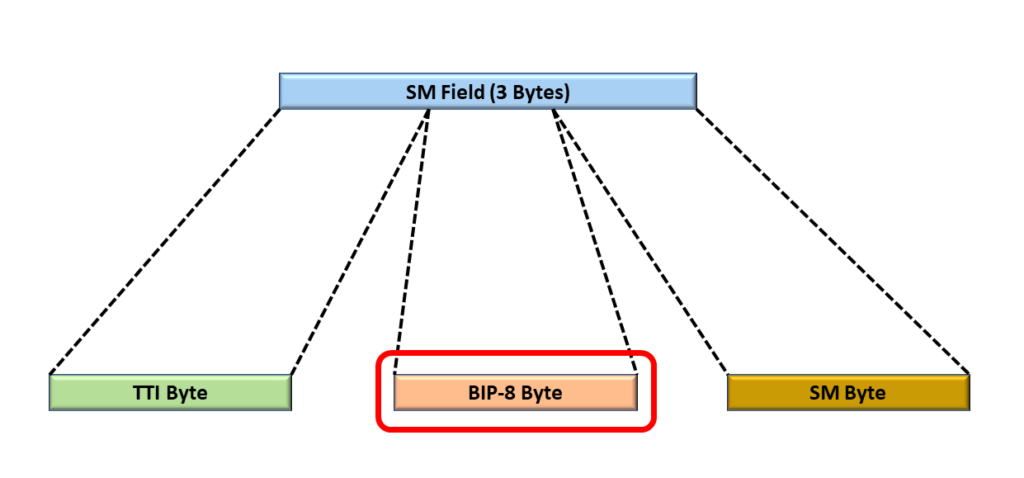
Section Monitoring Field with the SM-BIP-8 Byte Highlighted

Figure 6, Illustration of the SM Field with the SM-BIP-8 Byte field highlighted.

The purpose of the BIP-8 Byte field is to permit the receiving STE to perform error checking (and reporting) on each OTU frame it receives.

Without going into many details, the transmitting STE will compute the value for the BIP-8 Byte (based upon the data within the OPU Payload of a given OTU frame).
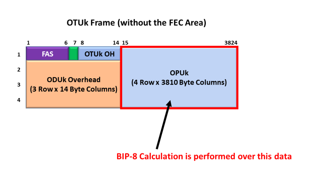
Section Monitoring BIP-8 Calculation Region

Figure 7, OPU Payload Data that the Transmitting STE uses to Compute the SM-BIP-8 Value

The transmitting STE will then insert this BIP-8 Byte within the BIP-8 Byte (of a specific OTU frame).

Section Monitoring BIP-8 Calculation and Insertion Region

Figure 8, Transmitting STE inserting the SM-BIP-8 Value into a Specific Location within the OTU data stream.

The transmitting STE will then transmit this SM-BIP-8 value (along with the rest of the data within the SM field and the OTU data stream) to the remote receiving STE.

As this Receiving STE receives and accepts an OTU data stream, it also locally computes its own value for the SM-BIP-8 byte-field (based on the data within the OPU Payload). The Receiving STE will also read in the SM-BIP-8 value (the transmitting STE computed and inserted into the SM-byte within the OTU data stream).

If the Receiving STE determines that the SM-BIP-8 value (that it reads from the SM field within the OTU data-stream) matches that of its locally computed SM-BIP-8, then it will determine that the Receive STE received an OTU frame in an un-erred manner.

On the other hand, if the Receiving STE determines that the SM-BIP-8 value (that it reads from the SM-field within the OTU data-stream) differs from that within its locally computed SM-BIP-8 value, then it will determine that the Receive STE received some OTU data in an erred manner.

The SM-BIP-8 blog post presents a detailed discussion on how the Transmitting STE computes the SM-BIP-8 value and inserts it into the SM field within the OTU frame.

What is the SM Byte field (within the SM field)?

I present an illustration of the SM field with the SM Byte field Highlighted in Figure 7.
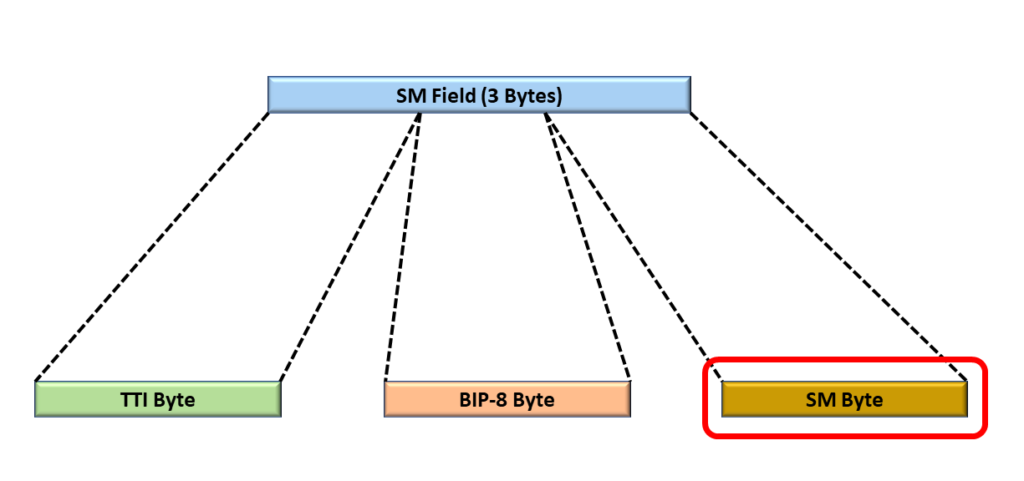
SM Field with the SM Byte Highlighted

Figure 7, Illustration of the SM-field with the SM-byte highlighted

However, if we were to take a closer look at the SM byte (within the SM-byte), we could see that the SM-byte would consist of multiple bit fields, as shown below in Figure 8.

Section Monitoring Byte with the SM-BEI field Highlighted

Figure 8, A Closer Look at the SM-byte-field within the SM-field

Figure 8 shows that the SM-byte consists of the following bit or nibble fields.

  • BEI/BIAE Nibble-Field
  • BDI bit-field
  • IAE bit-field
  • RES field (2 bits in width)

I will briefly define these nibble and bit-fields within the SM-byte field.

BEI/BIAE – Backward Error Indicator/Backward Input Alignment Error

The Backward Error Indicator is a four-bit field that reflects the number of SM-BIP-8 errors detected by a Receiving STE (and flagged) within the remote recently received OTU frame. If this nibble field contains a value of 0x00 to 0x08, it is transporting the BEI value for a given OTU frame. Please see the blog post on the SM-BEI nibble field to learn more about this topic.

On the other hand, if the BEI/BIAE contains the value of 0x0B, then this reflects a BIAE (Back Input Alignment Error) condition. Please see the blog post on IAE and BIAE defects to learn more about this topic.

BDI – Backward Defect Indicator bit-field

If the local receiving STE declares a service-affecting defect, it will set the BDI bit-field (that it sends out to the remote terminal) to “1”. On the other hand, if the local receiving STE does not declare a service-affecting defect, it will set the BDI bit-field (that it sends out to the remote terminal) to “0”.

Please see the blog post on the SM-BDI Indicator to learn precisely how this signaling scheme works in an OTU connection.

IAE – Input Alignment Error Bit-field

It Receiving STE detects a frame slip event (upstream) within the incoming OTU data stream, then will set this IAE bit-field to “1”.

Please see the blog post on IAE and BIAE defects to learn more about this topic.

Conclusion

I have briefly discussed the Section Monitoring Overhead within this blog post. This write-up was intended to be introductory and kept at a high (and simple) level. Please check out those individual blog posts for more details on how we compute specific SMOH fields. I did not want to repeat this detailed material (calculating the SM-BIP-8 value, the SM-BEI value, etc.) in this blog post.

OTN – Lesson 9 – Video 7 – OTUk_TT_Sk Function

This post presents the 7th of the 11 Videos that covers training on Performance Monitoring at the OTUk Layer. This post focuses on the Sink Direction OTU-Layer Atomic Functions.

OTN – Lesson 9 – Video 7 – OTU Layer Sink Direction Circuitry/Functionality – Part 5

This blog post contains a video that starts our discussion of the OTUk_TT_Sk Atomic Function.  

This blog post contains the 5th video that discusses the Sink (or Receive) Direction Atomic Functions at the OTU Layer.  This video is also the 7th of the 11 videos for Lesson 9.  

This video focuses on the following:

  • What is the CI_SSF input pin?
  • Near-End Error Checking  – SM-BIP-8 Verification
  • Sending SM-BEI Information based upon SM-BIP-8 Verification results.  
  • Far-End Error Checking – SM-BEI Monitoring
  • What does it mean to declare or clear the SM-BDI (or dBDI – Backward Defect Indicator) defect condition.  

Continue reading “OTN – Lesson 9 – Video 7 – OTUk_TT_Sk Function”

Lesson 2 – OTU Framing

This post provides a comprehensive review and video training of the OTU frame and its overhead fields.

Lesson 2 – Optical Transport Unit Frame Training

This post includes a video that discusses the OTU (Optical Transport Unit) frames in considerable detail.  

In particular, this video will discuss the OTU frame format and the roles each of its overhead fields plays.

Continue reading “Lesson 2 – OTU Framing”

What is pF_EBC at the OTUk Layer?

This blog post briefly describes the term pF_EBC (Far-End Errored Block Error).

What is the pF_EBC (Far-End Errored Block Count) Performance Monitoring Parameter for the OTUk Layer?

The purpose of this blog post is to briefly define and describe the pF_EBC (Far-End Errored Block Count) Performance Monitoring parameter that the OTN (Sink) STE (or OTUk_TT_Sk Atomic Function) will compute and tally.

The Sink STE (or OTUk_TT_Sk function) will include information on the pF_EBC parameter within each Performance Monitoring report it sends to System Management.

NOTES:

  1. The OTN PTE (ODUP_TT_Sk Atomic Function) also monitors and generates information on the pF_EBC (Far-End Errored Block Count) parameter at the ODUk Layer. Please see the pF_EBC at ODUk Layer Post for more details on this parameter.
  2. Throughout this post, I will use the terms: OTN STE and OTUk_TT_Sk Function interchangeably. In the context of this blog post, these two terms mean the same thing.

Introduction

At the OTUk Layer, the OTN (Sink) STE is the entity that is responsible for detecting and reporting Far-End Errored Block Counts (or SM-BEI errors).

As the Sink STE receives and monitors its incoming OTUk signal, it will check for many things. It will continuously scan the incoming OTUk signal for bit (or symbol) errors (e.g., SM-BIP-8, FEC, etc.). It will also check for Service-Affecting defects (e.g., dTIM, dLOM, dLOF, dAIS, dLOS-P, etc.).

New Comprehensive OTN Training…Available Now. Click on the Banner Below to Learn More!!!

Discounts Available for a Short Time!!!

Definition of Terms:

Before we proceed, we need to define the following terms for this blog post:

  • Block: In this case, we define a block as an OTUk frame.
  • Far-End Errored Block: In this blog post, we define a far-end errored block as any OTUk frame that contains a value for the SM-BEI count that ranges anywhere between 1 and 8. Anytime the OTN STE receives a block with an SM-BEI count value of 0x0, we consider that block to be un-erred.

As the Sink STE checks the incoming OTUk signal for errors and defects, it will also record the total number of far-end errored blocks it detects for each one-second period.

At the end of a given one-second period, the Sink STE will load the total number of far-end errored block counts (detected in the most recent one-second period) into the variable pF_EBC.

The Sink STE will then report this value for pF_EBC to System Management as a part of its Performance Monitoring report.

Table 1 presents the number of blocks/second that each type of OTUk signal will transport for each value of k.

Table 1, Number of Blocks/Second for each OTUk Rate.

OTUk TypeNumber of Blocks/Second
OTU120,421
OTU282,026
OTU3329,492
OTU4856,388
OTUCnn x 860,177

So How does the OTN STE tally Errored Blocks for the pF_EBC parameter?

As the Sink STE receives and monitors its OTUk signal, it will continually check the SM-BEI counts within each incoming OTUk frame (or block).

Anytime the Sink STE receives an OTUk frame in which the SM-BEI value is anywhere from 1 to 8, it will increment its internal (pF_EBC Counter) by 1.

NOTE: This means that even if the Sink STE receives an SM-BEI value of “8”, it will still just increment its pF_EBC Counter by 1 (not 8).

Conversely, the Sink STE will not increment its internal pF_EBC Counter whenever it receives an OTUk frame (or block) that contains an SM-BEI value of 0, or 9 through 15. The Sink STE consider these type of OTUk frames to be un-erred.

At the end of each one-second period, the Sink STE will load the contents of this internal counter into the pF_EBC parameter. The Sink STE will then include that information within its Performance Monitor report that it sends to System Management.

Are there any Times or Conditions during which the Sink STE will NOT tally Errored Block Counts for the pF_EBC parameter?

ITU-T G.798 states that the OTUk_TT_Sk function will stop tallying Errored Blocks for the pF_EBC parameter whenever the upstream circuitry (e.g., the OTSi/OTUk_A_Sk or OTSiG/OTUk_A_Sk Atomic Function) asserts the CI_SSF input of the OTUk_TT_Sk function.

In other words, the Sink STE will not tally any Errored Block Counts (for the pF_EBC parameter) whenever it (e.g., the OTSi/OTUk_A_Sk or OTSiG/OTUk_A_Sk functions) declare any of the following service-affecting defect conditions.

NOTE: (*) – Indicates that one must have a membership to THE BEST DARN OTN TRAINING PRESENTATION…PERIOD!!!, to access this information.

Additionally, the OTUk_TT_Sk function is not supposed to increment any pF_EBC counts whenever it declares the dBIAE (Backward Input Alignment Error) defect condition.

Is there such a thing as Near-End Errored Block Counts?

Throughout this post, we have used the term Far-End Errored Block Count. Does this mean that there is another parameter called Near-End Errored Block Count?

Answer: Yes, there is such a parameter. See the Near-End Errored Block Count post at the OTUk Layer for more details.

Clueless about OTN? We Can Help!! Click on the Banner Below to Learn More.

Discounts Available for a Short Time!!

And Finally, Click on the Following Image for More OTN-Related Topics in this Blog.

OTN Related Blog

OTN Related Topics within this Blog

OTN Related Topics within this Blog General Topics Consequent Equations - What are they and How can you use them? ...

What is pN_EBC at the OTUk Layer?

This blog post briefly describes the Performance-Monitoring parameter or term pN_EBC (Near-End Errored Block Count) for the OTUk-Layer.

What is the pN_EBC (Near-End Errored Block Count) Performance-Monitoring Parameter for the OTUk Layer?

This blog post aims to briefly define and describe the pN_EBC (Near-End Errored Block Count) Performance Monitoring parameter that the Sink STE (or OTUk_TT_Sk Atomic Function) will compute and tally.

The Sink STE (or OTUk_TT_Sk function) will include information on the pN_EBC parameter within each Performance Monitoring report it sends to System Management.

NOTES:

  1. The OTN PTE (or ODUP_TT_Sk Atomic Function) also monitors and generates information on the pN_EBC (Near-End Errored Block Count) parameter at the ODUk Layer. Please see the pN_EBC at ODUk Layer Post for more details on this parameter.
  2. Throughout this post, I will use the terms: Sink STE and OTUk_TT_Sk Function interchangeably. In the context of this blog post, these two terms mean the same thing.

Introduction

At the OTUk Layer, the OTN (Sink) STE is the entity that is responsible for detecting and reporting Near-End Errored Block Counts (or SM-BIP-8 Errors).

NOTE: We refer to SM-BIP-8 errors as Near-End errors because these are errors that the Near-End Sink STE is detecting on its end. In contrast, we refer to the SM-BEI parameter as Far-End errors because that parameter reflects errors that a remote (or Far-End) Sink STE is detecting and reporting.

As the Sink STE receives and monitors its incoming OTUk signal, it will check for many things. It will continuously scan the incoming OTUk signal for bit (or symbol) errors (e.g., SM-BIP-8 errors, FEC errors, etc.) as well as Service-Affecting Defects (e.g., dTIM, dLOF, dLOM, dLOS-P, dAIS, etc.).

Definition of Terms:

Before we proceed, we need to define the following terms for this blog post:

  • Block: In this case, we define a block as an OTUk frame.
  • Errored Block: In this blog post, we define an errored block as any OTUk frame (or block) that contains at least one SM-BIP-8 error.

As the Sink STE checks the incoming OTUk signal for errors and defects, it will also keep a count of the number of errored blocks it detects for each one-second period.

At the end of a given one-second period, the Sink STE will load the total number of errored block counts (detected and tallied in the most recent one-second period) into the variable pN_EBC.

Since each type of OTUk signal (for a given value of k) transmits a different number of OTUk frames than does another OTUk signal (with a different value for k), each OTUk type will transmit a different number of blocks/second, as we show below in Table 1.

Table 1, Number of Blocks/Second for each OTUk Rate

OTUk TypeNumber of Blocks/Second
OTU120,421
OTU282,026
OTU3329,492
OTU4856,388
OTUCnn x 860,177

So How does the OTN STE tally Errored Blocks for the pN_EBC parameter?

As the Sink STE receives and monitors its OTUk signal, it will continually check for SM-BIP-8 errors.

Anytime the Sink STE receives an OTUk frame that contains at least one SM-BIP-8 error, then it will increment its internal (pN_EBC Counter) by 1.

Conversely, the Sink STE does not increment its internal pN_EBC Counter whenever it receives an OTUk frame that contains 0 SM-BIP-8 errors.

At the end of each one-second period, the Sink STE will load the contents of this internal counter into the pN_EBC parameter and include that information within its Performance Monitor report that it sends to System Management.

New Comprehensive OTN Training…Available Now. Click on the Banner Below to Learn More!!!

Discounts Available for a Short Time!!!

Are there any Times or Conditions during which the OTN STE will NOT tally Errored Block Counts for the pN_EBC parameter?

Yes, ITU-T G.798 states that the OTUk_TT_Sk function will stop tallying Errored Blocks for the pN_EBC parameter whenever the upstream circuitry (e.g., the OTSi/OTUk_A_Sk or OTSiG/OTUk_A_Sk Atomic function) asserts the CI_SSF input of the OTUk_TT_Sk function.

In other words, the OTN STE will not tally any Errored Block Counts (for the pN_EBC parameter) whenever it (e.g., the OTSi/OTUk_A_Sk or OTSiG/OTUk_A_Sk functions) declares any of the following service-affecting defects conditions.

NOTE: (*) indicates that you must have a membership with THE BEST DARN OTN TRAINING PRESENTATION…PERIOD!!!, to be able to access these lessons.

Additionally, the OTUk_TT_Sk function is not supposed to increment any pN_EBC counts whenever it declares the dIAE (Input Alignment Error) defect condition.

Is there such a thing as Far-End Errored Block Counts?

Throughout this post, we have used the term Near-End Errored Block Count. Does this mean that there is another parameter called Far-End Errored Block Count?

Answer: Yes, there is such a parameter. Please see the Far-End Errored Block Count post at the OTUk Layer for more details.

Clueless about OTN? We Can Help!!! Click on the Banner Below to Learn More.

Discounts Available for a Short Time!!

And Finally, Click on the Following Image for More OTN-Related Topics in this Blog

OTN Related Blog

OTN Related Topics within this Blog

OTN Related Topics within this Blog General Topics Consequent Equations - What are they and How can you use them? ...