What is the Trail-Trace Identifier (TTI) Message?
We transport Trail Trace Identifier (TTI) messages at the OTU Layer, the ODU Layer, and for the (as many as 6) TCM Layers. In this blog post, I will talk about the type of data we transport within TTI Messages.
I illustrate the byte format of the Trail-Trace Identifier (TTI) message below in Figure 1.

Figure 1, Illustration of the Byte Format of the Trail-Trace Identifier (TTI) Message
Figure 1 shows that the Trail-Trace Identifier message is:
- 64 bytes in length,
- It consists of the following fields:
- 16 bytes of SAPI (Source Access Point Identifier)
- 16 bytes of DAPI (Destination Access Point Identifier), and
- 32 bytes of Operator Specific data
- We always synchronize our transmission of the TTI Messages with the MFAS byte.
- This means that we always transmit the first byte of the SAPI field (SAPI[0]) whenever the six LSBs of the MFAS value are [0, 0, 0, 0, 0, 0], and
- We transmit the last (or 64th byte of the TTI Message) whenever the six LSBs of the MFAS value are [1, 1, 1, 1, 1, 1].
Hence, we not only show the byte format of the Trail-Trace Identifier Message (in Figure 1), but we also show the sequence in which we transmit the byte within the TTI Message.
What Does SAPI (or Source Access Point Identifier) and DAPI (Destination Access Point Identifier) Mean?
The SAPI is a 16-byte sequence (or a subset of data) within the TTI Message.
The first byte of the SAPI field (SAPI[0]) is always set to 0x00.
The remaining 15 bytes (e.g., SAPI[1] to SAPI[15] contain the 15-byte (or 15-character) Source Access Point Identifier.
The first bit of the SAPI field (within bytes 1 through 15) will be set to “0”. Hence, each SAPI byte field is a 7-bit character field.
I highlight the 16-byte SAPI field within the TTI Message in Figure 2.
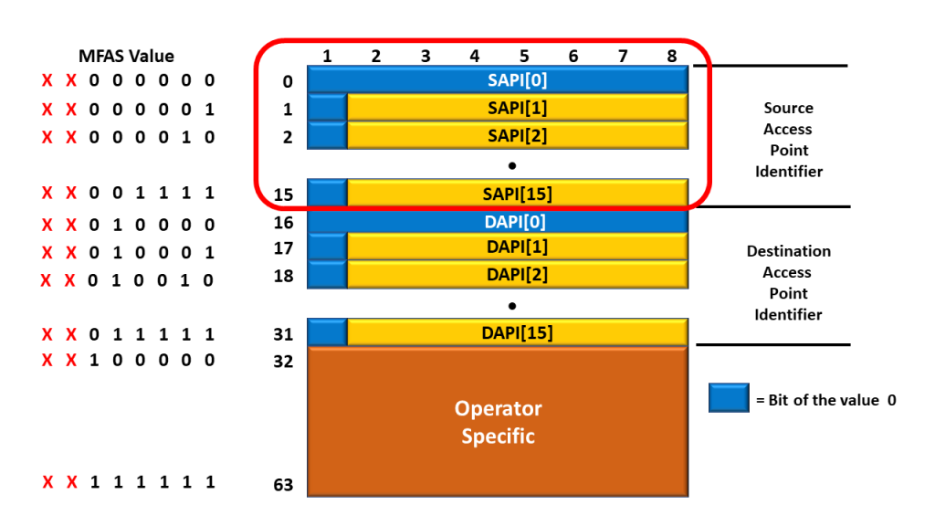
Figure 2, The 16-byte SAPI field.
Likewise, for the DAPI (Destination Access Point Identifier) field.
We always transmit the first byte of the DAPI field, DAPI[0] coincident whenever the 6 LSBs of MFAS are [0, 1, 0, 0, 0, 0].
I highlight the 16-byte DAPI field within the TTI Message in Figure 3.
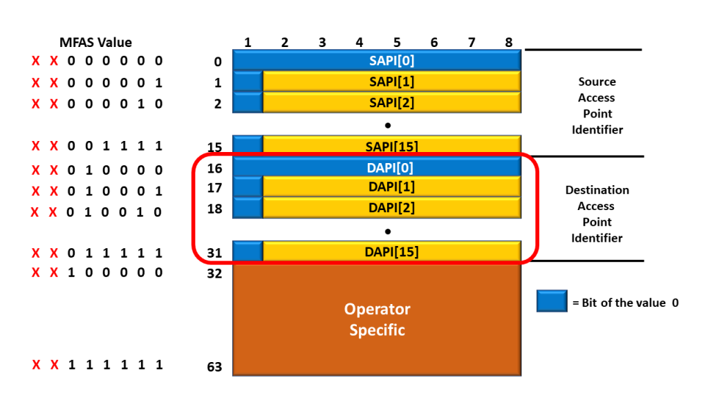
Figure 3, The 16-byte DAPI field.
Access Point Identifier (SAPI and DAPI) Features
Each API (or Access Point Identifier) must have the following features (and I’m quoting ITU-T G.709):
- Each API must be globally unique in its layer network.
- Where it may be expected that the access point may be required for path set-up across an inter-operator boundary, the access point identifier must be available to other network operators.
- The access point identifier should not change while the access point remains in existence.
- The access point identifier should identify the country and network operator responsible for routing to and from the access point.
- The set of all access point identifiers belonging to a single administrative layer network should form a single access point identification scheme.
- The scheme of access point identifiers for each administrative layer network can be independent of the scheme in any other administrative layer network.
The standards recommend that the ODUk, OTUk, and OTS each have the access point identification scheme based on a tree-link format to aid routing control search algorithms. The access point identifier should be globally unambiguous.
Additionally, according to Figures 1, 2, and 3, the network must set the first bit (within each byte of the SAPI and the DAPI) to “0”. Hence, we represent the SAPI and DAPI values with 15 7-bit characters.
What Kind of Data Do We Transport via the SAPI and DAPI Fields within the TTI Messages?
I earlier mentioned the following:
- Each TTI Message contains a 16-byte SAPI and 16-byte DAPI field
- However, the network set the first byte of each SAPI and DAPI field to an all-zeros pattern.
- In the remaining 15 bytes (of the SAPI and DAPI fields), the most significant bit-field is set to “0”.
- This means that the SAPI and DAPI fields carry 15 7-bit fields.
ITU-T G.709 states that “the access point identifier (SAPI, DAPI) shall consist of a three-character international segment (or sequence) and a twelve-character national segment.” I illustrate the basic structure for the Access Point Identifier (SAPI and DAPI) below in Figure 4.
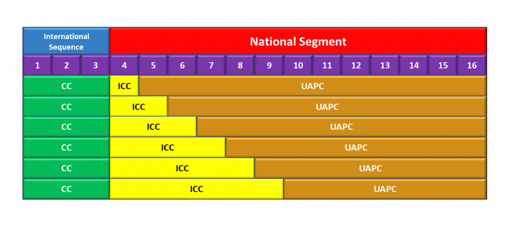
Figure 4, Access Identifier Structure (for both SAPI and DAPI)
The international segment (or international sequence) field consists of a three-character ISO 3166 geographic/political Country Code (G/PCC). The country code (CC) shall be based on the three-character uppercase alphabetic ISO 3166 country code (e.g., USA, FRA).
The national segment field consists of two subfields: the ITU carrier code (ICC) is followed by a unique access point code (UAPC).
The ITU carrier code is a code assigned to a network operator service provider, maintained by the ITU-T Telecommunication Standardization Bureau (TSB) as per ITU-T M.1400. This code shall consist of 1 to 6 left-justified characters, alphabetic, or leading alphabetic with trailing numeric.
The unique access point code shall be a matter for the organization to which the country code and ITU carrier code have been assigned, provided that uniqueness is guaranteed. This code shall consist of 6 to 11 characters, with trailing NUL, completing the 12-character national segment.
Clueless About OTN? We Can Help! Click on the Banner Below to Learn More!
Discounts Available for a Short Time!!

So What Does All This Mean for STE Equipment?
All of this means the following:
- Each piece of Section Terminating Equipment (STE) contains a unique 15-character (7-bit) Access Point Identifier value.
- In other words, no two STEs (in the world) can share the same 15-character Access Point Identifier value.
- The ITU and the nation (that the STE resides within) dictate the exact Access Point Identifier value (that we assign to a given STE).
- Whenever a given STE transmits a TTI message to another STE, it will use the SAPI value to identify itself (the Source STE). It will also use the DAPI value to identify the Destination STE (that it sends the TTI Message to).
We Also Deal with TTI Messages with PTE (Path Terminating Equipment) and TCMTE (Tandem Connection Terminating Equipment) – Do These Rules apply to the ODU Layer and the ODUT Layers as Well?
The answer is yes.
- Each piece of Path Terminating Equipment (PTE) contains a unique 15-character (7-bit) Access Point Identifier value.
- The ITU and the nation (that the PTE resides within) dictate the exact Access Point Identifier value (that we assign to a given PTE).
- Whenever a given PTE transmits a TTI message to another, it will use the SAPI value to identify itself (the Source PTE). It will also use the DAPI value to identify the Destination PTE (that it sends the TTI Message to).
Each of the four bullet points (above) applies to as many as 6 ODUT (or Tandem Connection Monitoring) Layers (within the TCMTE).
How About the Operator-Specific Portion of the TTI Message
We have no defined use for the Operator Specific Portion of the TTI Message for the time being. For now, we would reserve this 32-byte field for future use.
Which Byte-Fields Do We Use to Transport the TTI Message within an OTN Signal?
We transport TTI Messages within each of the following OTN Layers:
- OTU – Section Monitoring Overhead
- ODU – Path Monitoring Overhead, and
- As many as 6 Tandem Connection Monitoring Layers (TCM01 to TCM06)
Transporting TTI Messages at the OTU-Layer
At the OTU Layer, we will use the SM (Section Monitoring) field within each OTU frame to transport TTI Messages. I illustrate an OTU frame with the SM field highlighted in Figure 5.
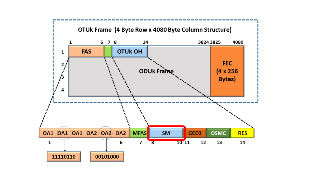
Figure 5, We Use the Section Monitoring (SM) field to transport the TTI Messages.
The SM field is a 3-byte field. In Figure 6, I zoom in and expand the SM field (to reveal the 3 bytes within the SM field). We transport the TTI Messages (within an OTU frame) via the TTI byte I show below in Figure 6.
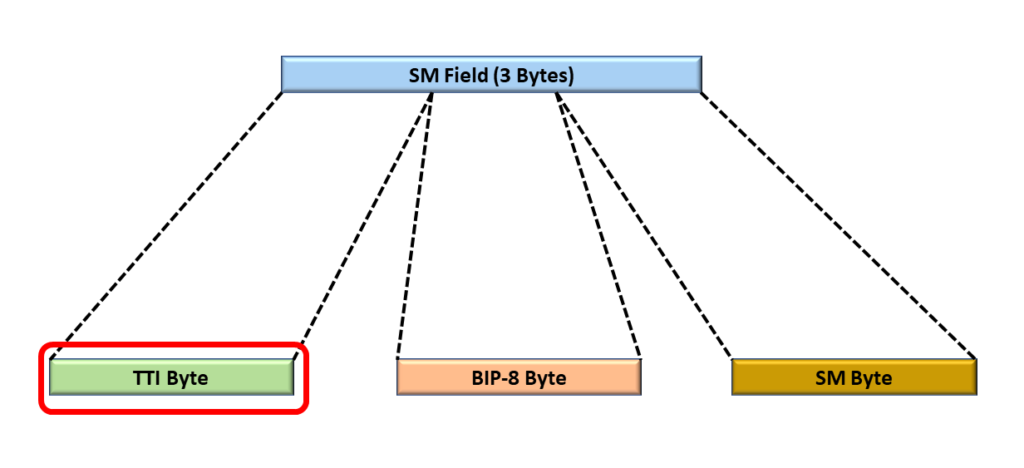
Figure 6, We Identify the TTI (Trail Trace Identifier) Byte within the SM Field – That We Use to Transport TTI Messages via an OTU signal.
Transporting TTI Messages at the ODU Layer
At the ODU Layer, we will use the PM (Path Monitoring) field within each ODU frame to transport TTI Messages. I illustrate an ODU frame with the PM field highlighted in Figure 7.
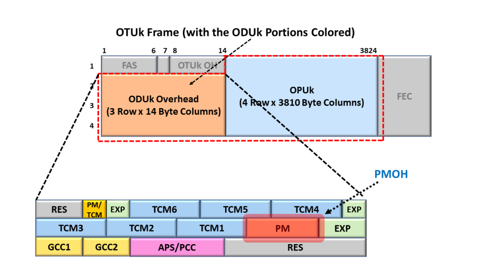
Figure 7, We Use the Path Monitoring (PM) field to transport the TTI Messages.
The PM field is also a 3-byte field. In Figure 8, I zoom in and expand the PM field (to reveal the 3 bytes within the PM field). We transport the TTI Messages (within an ODU signal) via the TTI byte that I show below in Figure 8.

Figure 8, We Identify the TTI (Trail Trace Identifier) Byte within the PM Field – That We Use to Transport TTI Messages via an ODU signal.
Transporting TTI Messages at (as many as) 6 ODUT Layers – for Tandem Connection Monitoring
At the ODUT Layers, we will use the SM (Section Monitoring) field within as many as six (6) TCMOH fields within each ODUT frame to transport TTI Messages. I illustrate an ODU/ODUT frame with the 6 TCMOH fields highlighted in Figure 9.
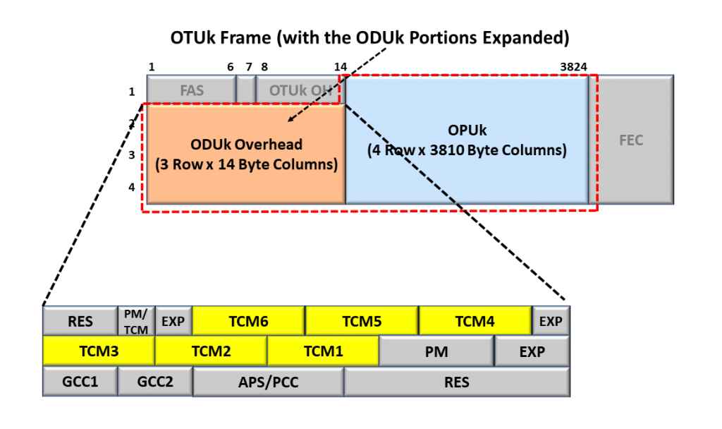
Figure 9, An ODU Frame with each of the 6 TCMOH Fields Highlighted
Each of the TCM fields is also a 3-byte field. In Figure 10, I zoom in and expand the TCM field (to reveal the 3 bytes within each TCM field). We transport the TTI Messages (within an ODUT signal) via the TTI byte that I show below in Figure 10.
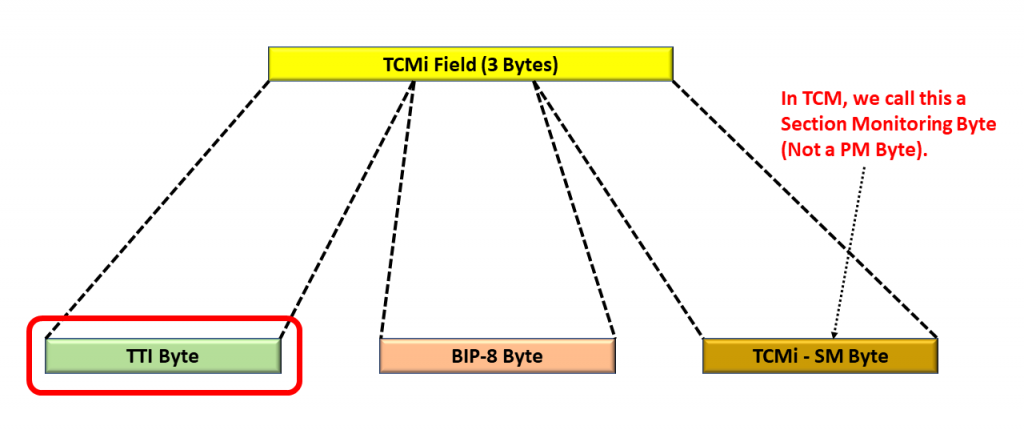
Figure 10, We Identify the TTI (Trail Trace Identifier) Byte within a given TCM Field – That We Use to Transport TTI Messages via an ODUT signal.
To be clear, we can transport as many as 8 TTI messages independently through an OTN signal at a given time.
- One TTI Message at the OTU Layer (via the TTI-byte-field within the SM byte)
- One TTI Message at the ODU Layer (via the TTI-byte-field within the PM byte), and
- As many as 6 TTI Messages at each (of 6 possible) ODUT/TCM Layers (via the TTI byte-field within the SM byte).
Please see the relevant post for more details on how we transport TTI Messages at a given OTN Network Layer.