What is the OTUk/ODUk_A_So Atomic Function?
We formally call the OTUk/ODUk_A_So Atomic Function the OTUk to ODUk Adaptation Source Function.
Introduction
The OTUk/ODUk_A_So function is any circuit that (1) accepts an ODUk signal and (2) adapts (or maps) it into an OTUk signal for transmission to the following Trail Termination Function.
NOTE: If we are working with a Fully-Compliant OTUk frame, then the OTUk/ODUk_A_So function will synchronously map each ODUk frame into the OTUk frame.
On the other hand, if we are working with a Functionally-Compliant OTUkV frame, this mapping might be asynchronous.
In this post, we will assume that we are working with a Fully-Compliant OTUk frame.
NOTE: We discuss the OTUk/ODUk_A_So function in detail in Lesson 9, within THE BEST DARN OTN TRAINING PRESENTATION…PERIOD!!!
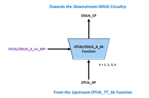
Figure 1 presents a simple illustration of the OTUk/ODUk_A_So function.

Figure 1, Simple Illustration of the OTUk/ODUk_A_So function
As the OTUk/ODUk_A_So function converts an ODUk signal into an OTUk signal, it will encapsulate each ODUk frame into an OTUk frame by adding the OTUk Overhead to the ODUk structure.
Please note that the OTUk/ODUk_A_So function will only insert default values for the SMOH (Section Monitoring Overhead) within the OTUk overhead.
Functional Block Diagram for the OTUk/ODUk_A_So Function
Figure 2 presents a Functional Block Diagram for the OTUk/ODUk_A_So function.

Figure 2, Functional Block Diagram for the OTUk/ODUk_A_So function
Interfaces within the OTUk/ODUk_A_So Function
Figure 2 shows that this function consists of three different interfaces.
- ODUk_CP – The ODUk Connection Point. The ODUk_CP is the interface where the ODUk-client supplies ODUk characteristic information (CI) to the OTUk/ODUk_A_So function input.
- OTUk_AP – The OTUk Access Point. There is where the OTUk/ODUk_A_So function outputs OTUk data, clock, frame, and multi-frame signals (for the outbound OTUk data-stream) to downstream circuitry (towards the OTUk_TT_So function).
- OTUk/ODUk_So_MP – The Function Management Point. This interface permits the function user to exercise control of the activity within the OTUk/ODUk_A_So function.
Figure 2 shows that the ODUk-client function (connected to the ODUk_CP Interface – of the OTUk/ODUk_A_So function) will supply the following signals to this function.
- CI_D – ODUk Data-Stream
- CI_CK – ODUk Clock Signal
- CI_FS – ODUk Frame Start Signal
- CI_MFS – ODUk Multiframe Start Signal
- CI_APS – ODUk APS Communication Channel
Clueless about OTN? We Can Help!!! Click on the Banner Below to Learn More!!!
Corporate Discounts Available!!

So What Does This Function Do?
The OTUk/ODUk_A_So function will perform the following operations on these signals.
Optionally Generates the ODUk-LCK Maintenance Signal
The function allows the user to configure the OTUk/ODUk_A_So function to generate the ODUk-LCK maintenance signal upon command internally.
The user can implement this command by setting the MI_AdminState input pin (at the Management Port) into the LOCKED State.
Whenever the user sets the MI_AdminState input into the LOCKED State and commands the OTUk/ODUk_A_So function to generate the ODUk-LCK maintenance signal, the timing, framing, and multi-framing for this ODUk-LCK signal will be based on the CI_CK, CI_FS and CI_MFS inputs (at the ODUk_CP Interface).
NOTE: In this case, the ODUk-LCK maintenance signal will replace the ODUk traffic carrying user/client data.
This function will, in turn, map this replacement signal into an OTUk data stream.
Please see the post on the ODUk-LCK maintenance signal for more details about the ODUk-LCK maintenance signal.
Allows User to Insert APS (Automatic Protection Switching) Commands into the APS Channel (within the ODUk-PMOH).
The OTUk/ODUk_A_So function permits the user to access the APS channel (within this ODUk signal) via some inputs (at both the OTUk/ODUk_A_So_MP and the ODUk_CP Interfaces).
More specifically, this function allows the user to enable or disable the APS Channel and configure this function to operate at a specific APS Level through the MI_APS_En and MI_APS_LVL inputs (via the OTUk/ODUk_A_So_MP Interface).
Additionally, this function permits the user to insert their own APS Commands into the APS/PCC Channel within the ODUk Overhead via the CI_APS input (at the ODUk_CP Interface).
NOTE: Please see the relevant post on the APS/PCC Channel to learn more about the APS Channel.
Generates OTUk Clock, FS (Frame Start), and MFS (Multi-Frame Start) Signals via the OTUk_AP Interface
The OTUk/ODUk_A_So function will synthesize the clock (AI_CK), frame start (AI_FS), and multi-frame start (AI_MFS) signals for the outbound OTUk signal via the OTUk_AP Interface.
The OTSiG/OTUk_A_So or OTSi/OTUk_A_So function (downstream) will use these signals to generate and insert the FAS and MFAS fields into the correct locations within the outbound OTUk data stream.
Generates the IAE (Input Alignment Error) Indicator for the downstream OTUk_TT_So function
The OTUk/ODUk_A_So function will generate the IAE (Input Alignment Error) indicator anytime it detects a frame-slip within the incoming ODUk signal (e.g., CI_FS) via the ODUk_CP Interface.
In other words, if this function detects the CI_FS signal pulsing TRUE during an unexpected clock cycle (CI_CK), then this function will drive the AI_IAE output pin HIGH.
Whenever the OTUk/ODUk_A_So function drives the AI_IAE output pin HIGH, it signals an Input Alignment Error Event. The OTUk/ODUk_A_So function will drive the AI_IAE output signal to the downstream OTUk_TT_So function.
The downstream OTUk_TT_So function will accept and perform another process with this AI_IAE output signal.
The OTUk/ODUk_A_So function will keep the AI_IAE output pin HIGH until the upstream (ODUk-circuitry) starts to assert the CI_FS input indicator during the correct (or expected) CI_CK period, once again.
Generate and Route the OTUk Data-Stream to downstream circuitry
This function will output a data stream via the AI_D output, which I will call a partial OTUk data stream.
This data stream will not contain the FAS, MFAS, or the FEC fields.
It will include the ODUk-portion of the OTUk frame and the default values for the various OTUk Overhead Fields (e.g., the Section Monitoring Overhead – SMOH).
We will then route this data stream to other circuitry (e.g., the OTUk_TT_So function) for further processing.
List of Input and Output Signals for the OTUk/ODUk_A_So Function
Table 1 presents a list and description for each OTUk/ODUk_A_So function input and output ports.
Table 1, List and Definition for each Input and Output Signal in the OTUk/ODUk_A_So function
| Signal Name | Type | Description |
| ODUk_CP Interface | | |
| CI_D | Input | ODUk Characteristic Information - Data Input:
The ODUk-client is expected to input the ODUk data via this input. This ODUk data will contain all portions of the ODUk frame. |
| CI_CK | Input | ODUk Characteristic Information - Clock Input:
This clock signal will sample all data that the ODUk-client supplies to the CI_D, CI_FS, CI_MFS and CI_APS inputs.
The OTUk/ODUk_A_So function will also use this clock signal as its timing source. |
| CI_FS | Input | ODUk Characteristic Information - Frame Start Input:
The ODUk-client equipment will drive this signal TRUE; coincident to whenever it is supplying the very first bit or byte (of a given OTUk frame) to the CI_D input.
The ODUk-client is expected to assert this signal once for each ODUk frame period.
The OTUk/ODUk_A_So function will also use this input signal to determine if it should declare the IAE condition, via the AI_IAE output pin. |
| CI_MFS | Input | ODUk Characteristic Information - Multiframe Start Input:
The system-side equipment will drive this signal TRUE coincident to whenever it is supplying the very first bit or byte (of a given ODUk/OTUk Superframe) to the CI_D input.
The ODUk-client is expected to assert this signal once for each OTUk/ODUk superframe period, or once every 256 ODUk frame periods. |
| CI_APS | Input | ODUk Characteristic Information - APS Channel Data:
The system-side equipment is expected to apply the APS Channel to this input.
The function user must set the MI_APS_En input to TRUE and must place a valid value (for APS Level) at the MI_APS_LVL input pins, or the OTUk/ODUk_A_So function will ignore the data at this input.
The OTUk/ODUk_A_So function will map this data into the APS/PCC channel within the ODUk data-stream.
Please see the blog post about the APS/PCC channel for more information. |
| OTUk_AP Interface | | |
| AI_D | Output | OTUk Adapted Information - OTUk Data Output:
The OTUk/ODUk_A_So function will take all of the data (that the ODUk-client applies to both the CI_D and CI_APS input pin) and will combine this data together to form a bare-bones OTUk data-stream.
NOTE: This OTUk data will contain the following fields.
- Default OTUk SMOH data,
- The contents of the APS/PCC channel and
- The rest of the OTUk frame.
This OTUk data-stream will not include the FAS, MFAS or FEC fields. Additionally, the downstream OTUk_TT_So function will compute and generate the correct values for the OTUk-SMOH. |
| AI_CK | Output | OTUk Adapted Information - Clock Output:
As the OTUk_AP Interface outputs data via the AI_D, AI_FS, AI_MFS and AI_IAE outputs; it will updata all of this data on one of the edges of this clock output signal. |
| AI_FS | Output | OTUk Adapted Information - Frame Start Output:
The OTUk_AP Interface will pulse this output signal HIGH whenever the OTUk_AP Interface outputs the very first bit (or byte) of a new OTUk frame, via the AI_D output.
The OTUk_AP Interface will pulse this output HIGH once for each outbound OTUk frame. |
| AI_MFS | Output | OTUk Adapted Information - Multiframe Start Output:
The OTUk_AP Interface will pulse this output signal HIGH whenever the OTUk_AP Interface outputs the very first bit (or byte) of a new OTUk superframe, via the AI_D output.
The OTUk_AP Interface will pulse this output HIGH once for each OTUk Superframe (or once each 256 OTUk frames). |
| AI_IAE | Output | OTUk Adapted Information - Input Alignment Error Output:
The OTUk_AP Interface will drive this output signal HIGH whenever the OTUk/ODUk_A_So function detects a frame slip within the ODUk_CP Interface.
More specifically, if the OTUk/ODUk_A_So determines that the upstream equipment has pulses the CI_FS input at an unexpected CI_CK period, then this function will drive this output HIGH.
This function will keep this output signal HIGH until the OTUk/ODUk_A_So function starts to receive pulses at the CI_FS during the "expected" CI_CK periods again.
Once the OTUk/ODUk_A_So function starts to receive pulses at the CI_FS input (during the "expected" CI_CK period) then it will drive this output pin LOW. |
| OTUk/ODUk_A_So_MP Interface | | |
| MI_AdminState | Input | Management Interface - AdminState Input:
This input pin permits the user to configure the OTUk/ODUk_A_So function to operate in either the LOCKED State or the NORMAL state.
If the user configures this function to operate in the NORMAL state, then it will map NORMAL ODUk traffic (e.g., ODUk traffic that is carrying client-data) into an OTUk frame as it passes through this function.
Conversely, if the user configures this function to operate in the LOCKED state, then the function will generate and map the ODUk-LCK Maintenance signal into the outbound OTUk data-stream. |
| MI_APS_En | Input | Management Interface - APS Channel Enable Input:
This input pin permits the user to either enable or disable the OTUk/ODUk_A_So function to/from accessing the APS/PCC channel within the ODUk overhead.
Setting this input HIGH permits the OTUk/ODUk_A_So function to access (and send APS messages via) the APS/PCC channel.
Setting this input LOW prevents the OTUk/ODUk_A_So function from accessing (and sending APS messages) via the APS/PCC channel. |
| MI_APS_LVL | Input | Management Interface - APS Level:
This input permits the user to specify the APS Level, that this OTUk/ODUk_A_So function can use when it accesses the APS/PCC channel.
NOTES:
1. This input is ignored if MI_APS_En = FALSE.
2. There are 8 possible valid inputs to this port.
Please see the blog post on the APS/PCC channel for more information about this topic. |
Has Inflation got You Down? Our Price Discount Can Help You Beat Inflation and Help You To Become an Expert on OTN!!! Click on the Banner Below to Learn More!!
Discounts Available for a Short Time!!

For More Information on OTN Posts in this Blog, click on the Image below.

OTN Related Topics within this Blog General Topics Consequent Equations - What are they and How can you use them? ...