
The Line Layer
The Line Layer is the second highest layer within the SONET Reference Model.
The purpose of the Line Layer is to support the transmission of data between the Source and Sink Terminal of a given STS-N signal.
Figure 1 presents an illustration of some STS-1 and STS-3 circuitry that helps to define the Line.

Figure 1, Definition of an STS-N Line
In Figure 1, I show that an STS-3 Line Signal begins and ends at the STS-1 to the STS-3 MUX/DeMUX block (which originates and terminates the STS-3 signal).
What is an LTE – Line Terminating Equipment
Any piece of equipment that manages the transmission and reception of an STS-N data stream, from the point that we create this signal to the point where we terminate this signal.
An LTE will manage the transmission and reception of STS-N data via the Line Overhead (LOH) bytes.
The LOH bytes reside in (and are a subset of) what we often refer to as the “Transport Overhead” (TOH) bytes. Figure 2 illustrates the Line Overhead Bytes within an STS-1 Signal.

Figure 2, Illustration of the Line Overhead Bytes within an STS-1 Signal.
All LTEs are also STEs
Therefore, all LTEs will manage the transmission and reception of STS-N data via both the “SOH” and “LOH” bytes.
We briefly define the SOH bytes (within an STS-1 frame) in another blog post.
Description of the Line Overhead (LOH) Bytes
H1 and H2 Pointer Bytes
Figure 3 highlights the location of the H1 and H2 bytes within the LOH.
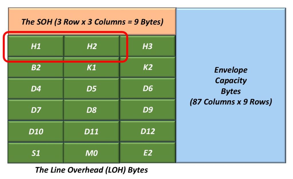
Figure 3, The Location of the H1 and H2 bytes within the LOH
The contents of the H1 and H2 bytes are used to indicate the offset between the location of these bytes and the first byte within the STS-1 Synchronous Payload Envelope (SPE).
An STS-1 Transmitter will compute a 10-bit pointer value and will insert this data into the H1 and H2 bytes within a given “outbound” STS-1 frame.
An STS-1 Receiver will use this 10-bit pointer to locate the SPE within the incoming STS-1 data stream.
I present a more detailed discussion of the H1 and H2 bytes in another blog post.
H3 Pointer Action Byte
Figure 4 highlights the location of the H3 byte within the LOH.
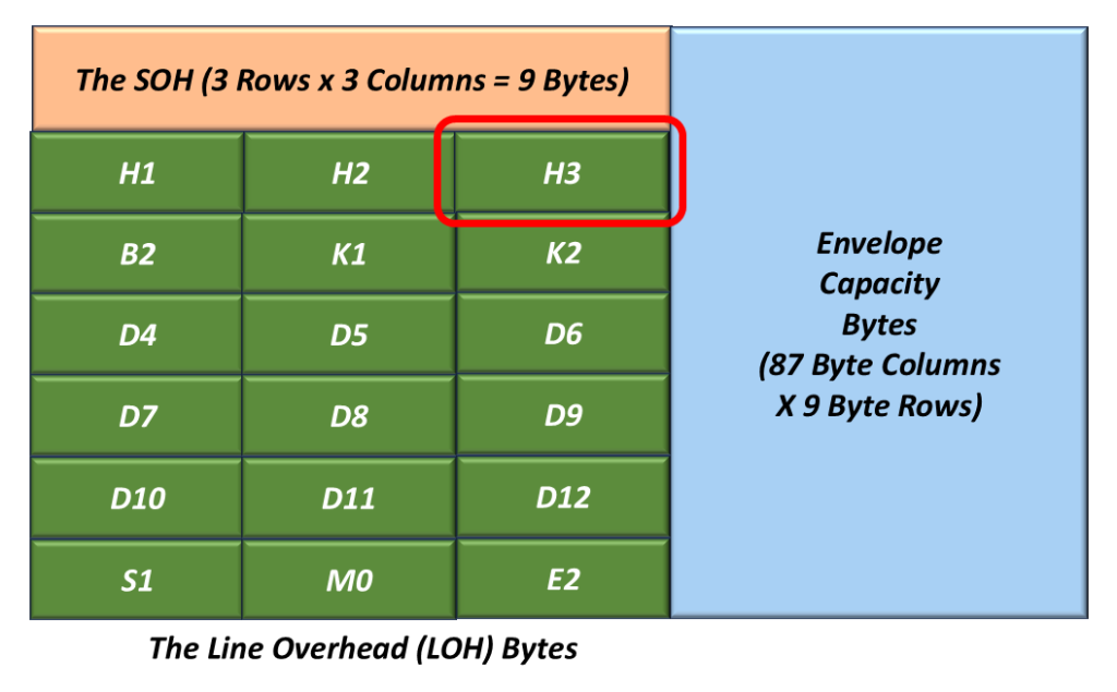
Figure 4, The Location of the H3 byte within the LOH.
We typically use the H3 byte for “Frequency” or “Pointer Justification” purposes.
I present a more detailed discussion of the H3 byte in another blog post.
The B2 Byte
Figure 5 presents the location of the B2 byte within the LOH.
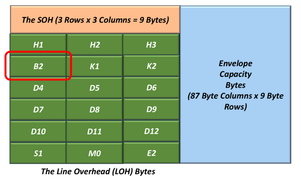
Figure 5, The Location of the B2 Byte within the LOH.
The Role of the Transmit STS-1 Terminal – B2 Byte
A Transmitting STS-1 Terminal will compute the contents of the B2 byte by performing a BIP-8 calculation over all bits within the LOH and the Envelope Capacity within a given “outbound” STS-1 frame (after scrambling).
This resulting byte value is inserted into the B2 Byte field (within the very next outbound STS-1 frame) before scrambling (of the current STS-1 frame).
The Role of the Receive STS-1 Terminal – B2 Byte
- As a Receiving STS-1 Terminal receives the LOH and the Envelope Capacity data (within a given STS-1 frame), it will compute its own BIP-8 value.
- Afterwards, the Receive STS-1 Terminal will compare the value of its “locally” computed BIP-8 value with the value residing within the B2 byte-field of the very next STS-1 frame.
- If the two values are the same, then the Receive STS-1 Terminal will “conclude” that it has received the LOH and Envelope Capacity data in an un-erred manner.
- If the two values are different, then the Receive STS-1 Terminal will “conclude” that it received the LOH and Envelope Capacity in an erred manner.
- We will discuss how SONET STEs should flag the occurrence of B2 byte errors in a future blog post.
NOTES:
- The B2 byte (in SONET) is analogous to the Section BIP within an OTU Frame.
- We will discuss how the Transmit STS-1 Terminal computes the B2 byte and how the Receive STS-1 Terminal verifies the B2 byte in another blog post.
The K1 and K2 (Automatic Protection Switching) Bytes
Figure 6 highlights the location of the K1 and K2 bytes within the LOH.
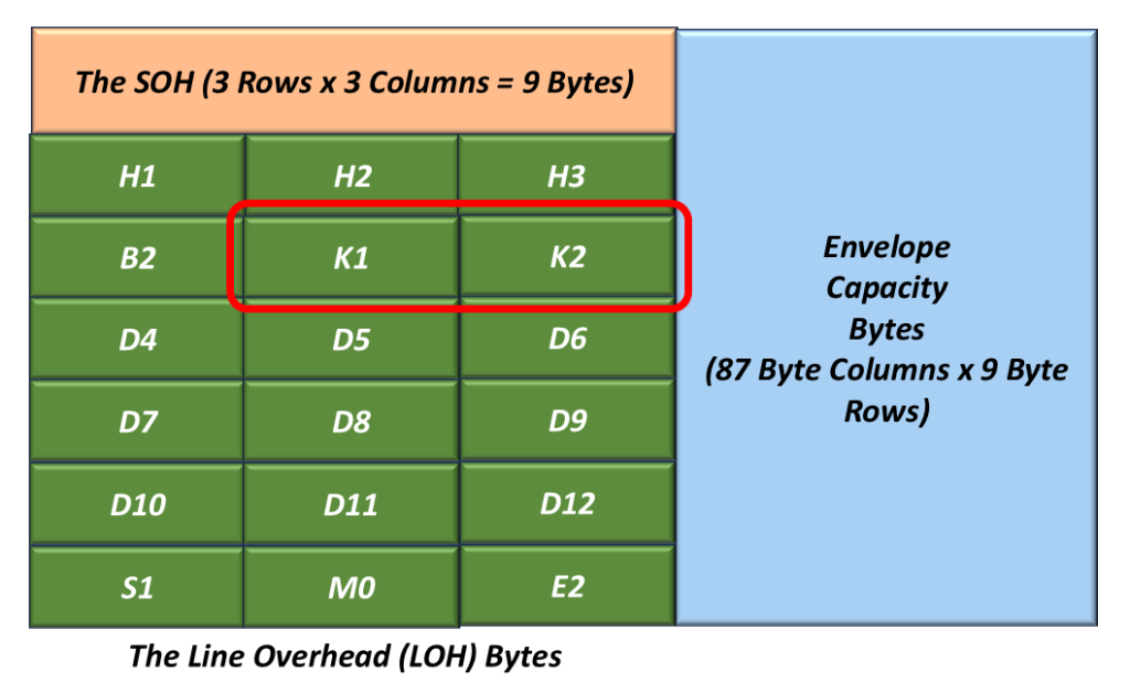
Figure 6, The Location of the K1 and K2 Bytes within the LOH.
The SONET Protocol uses the K1 and K2 bytes for the following purposes:
- To transport the APS signaling protocol (Used in BLSR and Linear APS schemes).
- A given LTE will use the K1 and K2 bytes to detect/clear the following defect conditions within a SONET signal.
- AIS-L (Line AIS) Defect
- RDI-L (Line – Remote Defect Inidicator).
We will discuss the APS Protocol in another blog post.
We will also discuss how the SONET Terminal transmits and declares the AIS-L and RDI-L defect conditions in another post.
The Line Data Communication Channel (D4 through D12) Bytes
Figure 7 highlights the location of the Line Data Communication Channel Bytes within the LOH

Figure 7, The Location of the Line DCC (Data Communication Channel) Bytes – D4 through D12 within the LOH
The D4 through D12 bytes are located in the first STS-1 of an STS-N and are considered as one 576kbps message-based channel for alarms, maintenance, control, monitoring and administering, and other communication needs.
This channel is available for internally generated, externally generated, and supplier-specific messages.
I will discuss what I mean by the expression: “the first STS-1 of an STS-N” in another blog post.
The S1 – Synchronization Status Byte
Figure 8 presents the location of the S1 Byte within the LOH.
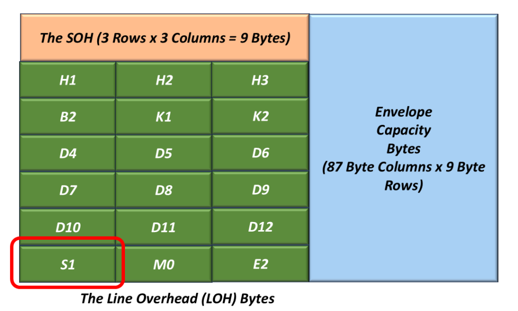
Figure 8, Illustration of the LOH with the S1 Byte Highlighted
We use this byte to transport the Synchronization Status Message (SSM).
I will discuss how we use the S1 byte in another blog post.
The M0 Byte – STS REI-L (Remote Error Indicator – Line)
Figure 9 presents the location of the M0 Byte within the LOH.
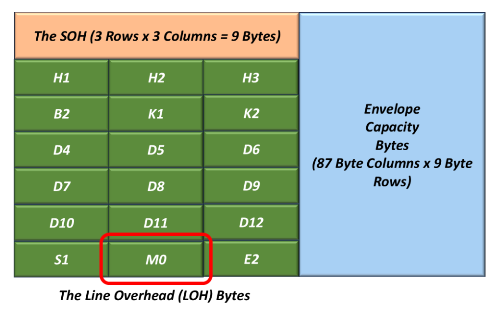
Figure 9, Location of the M0 Byte within the LOH.
The purpose of the M0 byte is to transmit the REI-L (Line – Remote Error Indicator) to a remote LTE.
REI-L conveys the error count detected by the LTE (within the B2 byte) back to its peer LTE.
We will discuss the REI-L indicator and how we use it in another blog post.
E2 Byte – Undefined
Figure 10 presents the location of the E2 byte within the LOH.
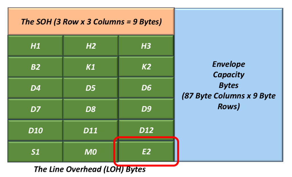
Figure 10, Location of the E2 Byte within the LOH.