Lesson 5/PT = 0x21/ODUflex – Mapping/Multiplexing n ODUflex Tributary Signals into an ODU3 Server Signal

This post describes how we map/multiplex some number of ODUflex tributary signals into an ODU3 server signal, using the PT = 0x21 Approach.

Mapping/Multiplexing Some Number of ODUflex Tributary Signals into an ODU3 Server Signal (PT = 0x21)

This blog post includes a video that shows how we map and multiplex some number of ODUflex Tributary Signals into an ODU3 Server Signal, using the PT = 0x21 Approach.

In particular, we discuss the following topics in this video.

  1. Subdividing the ODUflex signal into n separate 1.25 Gbps time-slots
  2. Using the GMP (Generic Mapping Procedure) to map the ODUflex tributary signal into its respective ODTU3.ts signal/frames.
  3. How to combine these ODTU3.ts signals (along with other signals – ODTU3.ts signals with other values for ts) into an ODU3 payload.
  4. Transporting the GMP Justification parameters from the Source PTE (where we map/multiplex these ODUflex tributary signals into an ODU3 server signal) to the Sink PTE (where we de-multiplex and de-map out the ODUflex tributary signals).
  5. A Review of the Multiplex Structure Identifiers (MSI) within this type of ODU3 server signal.

You can view this video below.

Continue reading “Lesson 5/PT = 0x21/ODUflex – Mapping/Multiplexing n ODUflex Tributary Signals into an ODU3 Server Signal”

Lesson 5/PT = 0x21/3 ODU2e – Mapping/Multiplexing 3 ODU2e Tributary Signals into an ODU3 Server Signal

This post describes how we map/multiplexing as many as 3 ODU2e tributary signals into an ODU3 server signal, using the PT = 0x21 Approach.

Mapping/Multiplexing 3 ODU2e Tributary Signals into an ODU3 Server Signal (PT = 0x21)

This blog post includes a video that shows how we map and multiplex as many as 3 ODU2e Tributary Signals into an ODU3 Server Signal, using the PT = 0x21 Approach.

In particular, we discuss the following topics in this video.

  1. Subdividing the ODU2e signal into nine (9) separate 1.25 Gbps time-slots.
  2. Using the GMP (Generic Mapping Procedure) to map the ODU2e tributary signal into their ODTU3.9 signal/frames.
  3. How to combine these ODTU3.9 signals (along with other signals, such as ODTU3.1 and ODTU13 signals) into an ODU3 payload.
  4. Transporting the GMP Justification parameters from the Source PTE (where we map/multiplex these ODU2e tributary signals into an ODU3 server signal) to the Sink PTE (where we de-multiplex and de-map out the ODU2e tributary signals).
  5. Multiplex Structure Identifiers within this type of ODU3 server signal.

You can view this video below.

Continue reading “Lesson 5/PT = 0x21/3 ODU2e – Mapping/Multiplexing 3 ODU2e Tributary Signals into an ODU3 Server Signal”

Lesson 5/PT = 0x21/32 ODU0 – Mapping/Multiplexing 32 ODU0 Tributary Signals into an ODU3 Server Signal

This post includes a video that first presents an introduction to the PT = 0x21 approach to Mapping/Multiplexing ODUj Tributary Signals into an ODUk Server Signal. This video also discusses how we map/multiplex as many as 32 ODU0 tributary signals into an ODU3 server signal

Introduction to PT = 0x21 and Mapping/Multiplexing 32 ODU0 Tributary Signals into an ODU3 Server Signal (PT = 0x21)

This blog post includes a video that:

  • Introduces the viewer to the PT = 0x21 Scheme for Mapping/Multiplexing Lower-Speed ODUj Tributary Signals into an ODUk Server Signal, and
  • Shows how we map and multiplex as many as 32 ODU0 Tributary Signals into an ODU3 Server Signal, using the PT = 0x21 Approach.

In this video, we discuss the following:

  • Using the GMP (Generic Mapping Procedure) to map each ODU0 tributary signal into their respective ODTU3.1 signal/frames
  • How to combine these ODTU3.1 signals and map them into an ODU3 payload
  • Transporting these GMP Justification parameters from the Source PTE (where we map/multiplex these ODU0 tributary signals into an ODU3 server signal) to the Sink PTE (where we de-multiplex and de-map out the ODU0 tributary signals)
  • A review of the Multiplex Structure Identifier (MSI) within this type of ODU3 signal

You can view this video below.

Continue reading “Lesson 5/PT = 0x21/32 ODU0 – Mapping/Multiplexing 32 ODU0 Tributary Signals into an ODU3 Server Signal”

OTN – Lesson 10 – Video 4M – ODUkP/ODUj-21_A_Sk Atomic Function

This post presents the 4th of the 6 Videos that covers training on the Peformance Monitoring of the ODUk Layer (for Multiplexed Applications). This post focuses on the Sink Direction ODU-Layer Atomic Functions.

OTN – Lesson 10 – Video 4M – Continuation with the ODUkP/ODUj-21_A_Sk Atomic Function

This blog post contains a video that continues our discussion of the ODUkP/ODUj-21_A_Sk Atomic Function.  Further, this video picks up (where we left off in Video 3M) where we were discussing the need to maintain synchronization with the OMFI byte-field, and

It proceeds to describe how the ODUkP/ODUj-21_A_Sk declares and clears the dLOOMFI defect condition as we walk through the dLOOMFI/In-Multi-Frame State Machine Diagram.  

Continue reading “OTN – Lesson 10 – Video 4M – ODUkP/ODUj-21_A_Sk Atomic Function”

Lesson 5 – PT = 0x21 Approach/ODU4 – Mapping/Multiplexing Lower-Speed ODUj Tributary Signals into an ODU4 Server Signal

This blog post provides an introduction to the PT = 0x21 Approach for Mapping/Multiplexing Lower-Speed ODUj Tributary Signals into an ODUk Server Signal. It also discusses the General Rules for Mapping/Multiplexing Lower-Speed ODUj Tributary Signals into an ODU4 Server Signal.

Lesson 5 – General Rules for Mapping/Multiplexing Lower-Speed ODUj Tributary Signals into an ODU4 Server Signal

Whenever you wish to map/multiplex Lower-Speed ODUj Tributary signals into an ODU4 Server Signal, things are a bit different from that if you were to map/multiplex these tributary signals into an ODU1, ODU2, or ODU3 server signal.  

For example, whenever we map/multiplex lower-speed ODUj tributary signals into an ODU4 server signal, we ALWAYS use GMP (Generic Mapping Procedure).  

This page includes a video that discusses the basic RULES for Mapping/Multiplexing Lower-Speed ODUj Tributary Signals into an OPU4/ODU4 Server Signal.  

Afterward, I present links to many videos that permit you to review the specific mapping/multiplexing cases you wish to learn about.   I list links to the following videos.

  • Mapping as Many as 80 ODU0 tributary signals into an ODU4 Server Signal
  • Mapping as Many as 40 ODU1 tributary signals  into an ODU4 Server Signal
  • Mapping as Many as 10 ODU2 or ODU2e tributary signals into an ODU4 Server Signal
  • Mapping as Many as 2 ODU3 tributary signals into ODU4 Server Signal
  • Mapping Some Number of ODUflex signals into an ODU4 Server Signal
  • A Summary of Everything We’ve Learned about Mapping/Multiplexing ODUj Tributaries into an ODU4 Server Signal.  

Continue reading “Lesson 5 – PT = 0x21 Approach/ODU4 – Mapping/Multiplexing Lower-Speed ODUj Tributary Signals into an ODU4 Server Signal”

Lesson 2 – OPU Framing

This blog post presents a training video on the OPU (or Optical Payload Unit) frames. This post also contains a written overview of OPU frames as well.

OTN Lesson 2 – OPU (Optical Payload Unit) Framing

An OPU (Optical Payload Unit) frame is that portion of an OTU (Optical Transport Unit) frame that carries and transports client data throughout the Optical Transport Network (OTN).

You can Check Out the Training Video on OPU Framing Below.

Click on the Link Below to See the ODU Training Video

Click on the Link Below to Return to the Main Lesson 2 Page.

The OPU frame is a subset of an ODU (Optical Data Unit) and an OTU (Optical Transport Unit) frame.

Where is the OPU Layer within the OTN Protocol Stack?

Figure 1 presents an illustration of the OTN Protocol Stack, with the OPU Layer Highlighted.

OTN Protocol Stack - OPU Layer Highlighted

Figure 1, Illustration of the OTN Protocol Stack, with the OPU Layer Highlighted

This figure shows that the OPU Layer is the closest layer to the Client Layer. We map the client data into OPU frames and transport them throughout the OTN.

The Basic Structure of the OPU Frame

I present an illustration of the Basic (or Generic) Structure of the OPU Frame below in Figure 2.

Generic OPUk Frame

Figure 2, Illustration of the Basic (or Generic) Structure of an OPU Frame

Each OPU frame is a 4 Row x 3810 byte-column structure. The OPU Frame consists of two basic types of fields.

  • The Payload Fields (which are the Pink-colored fields in Figure 2), and
  • The Overhead Fields (those non-Pink-colored fields on the left-hand side of the figure).

Each OPU frame contains 8 overhead bytes. And all OPU rates (except for the OPU4 frame) include 15,232 payload bytes. OPU4 frames have 15,200 payload bytes, as I show later in this post.

We use the Payload Fields to transport the client data and the Overhead fields for management purposes.

What Do the OPU Overhead Fields Manage?

In general, the OPU Overhead Fields (that I show in Figure 2) manage the following tasks.

  • They manage the mapping of client data into the OPU payload, and
  • These fields also (in turn) manage the de-mapping of client data from the OPU payload.
    • The JC1 – JC6, NJO, and PJO bytes support this effort.
  • They identify (to the OTN) the type of client signal that we are transporting via this particular OPUk signal.
    • The PSI byte supports this role.
  • And finally, they support mapping Lower-Speed ODUj Tributary signals into an OPU4 frame (in particular).
    • The OMFI byte supports this role.

What are some of the Various Types of OPU Frames

Throughout this training, we will be working with the following four types of OPU frames.

  • The BMP (Bit Synchronous Mapping Procedure) frame.
  • The AMP (Asynchronous Mapping Procedure) Applications
  • The GMP (Generic Mapping Procedure) Applications – up to OPU3 Rates
  • The GMP (Generic Mapping Procedure) Applications – for the OPU4 Rate

Let’s Discuss Each of these Types of OPU Frames below.

OPU Frames for BMP Applications

Figure 3 presents an illustration of an OPU Frame that supports BMP Mapping.

OPUk Frame for BMP Mapping Applications

Figure 3, Illustration of an OPU Frame – supporting BMP Mapping

This is by far the simplest OPU frame.

In this particular OPU frame, the JC1 through JC3 and the NJO bytes serve no real purpose other than to occupy space. Additionally, the PJO byte will always transport client data for BMP Mapping applications.

The PSI (Payload Structure Identifier) byte will repeatedly transmit the PSI Message. We will discuss the PSI Message later in this blog post.

Click Here to learn more about the Bit Synchronous Mapping Procedure (BMP) in Lesson 4.

OPU Frames for AMP Applications

Figure 4 illustrates an OPU frame that supports AMP Mapping Applications.

AMP Discussion - Basic Figure - Introduction of OPUk OH

Figure 4, Illustration of an OPU Frame – supporting AMP Mapping Applications

The OPU Frame in Figure 4 looks (and is) very similar to that for Figure 3. However, in the case of Figure 4, the JC1 through JC3, NJO, and PJO bytes are all active and play a significant role in AMP Mapping (or De-Mapping).

Please Click Here to learn more about AMP Mapping and these overhead fields in Lesson 4.

OPU Frames for GMP Applications – up to OPU3

Figure 5 presents an illustration of an OPU Frame that supports GMP Mapping. In this frame, we are looking at a figure that supports OPU rates from OPU0 up to OPU3.

OPU0 through OPU3 - GMP Applications

Figure 5, Illustration of an OPU Frame – supporting GMP Mapping Applications (OPU0, OPU1, OPU2, OPU3, and OPUflex).

As you can see, the OPU Overhead for this frame looks VERY different from that of Figures 3 and 4. AMP and BMP Mapping are closely related to each other. However, GMP is a VERY different mapping procedure from AMP or BMP.

Hence, GMP Mapping will require using 6 Justification Control fields (JC1 through JC6). Additionally, GMP does not use the NJO or PJO fields.

Finally, this brings us to the next (and final) type of OPU Frame.

OPU Frames for GMP Applications – OPU4 Applications

Figure 6 presents an illustration of an OPU Frame that also supports GMP Mapping applications. However, this particular figure is only applicable to the OPU4 Rate.

OPU Overhead - GMP Mapping - JC1 through JC6 Break down at the Bit-Level

Figure 6, Illustration of an OPU Frame – supporting GMP Mapping Applications (OPU4 ONLY)

The OPU Frame in Figure 6 looks very similar to that in Figure 5, with just two differences.

  • The OPU4 Frame has an OFMI byte-field in the OPU Overhead in Row 4, and
  • The OPU4 Frame has a total of 32-byte area reserved for Fixed Stuffing.

Both OPU Frames in Figures 5 and 6 have six (6) sets of Justification Control Bytes (JC1 through JC6). These Justification Control fields are required to support GMP Mapping.

How is the OPU4 Frame different from the other OPU Frames?

Each OPU frame I show in Figures 3, 4, and 5 has 15,232 bytes within their OPU Payload.

However, because the OPU4 frame has this 32-byte Fixed Stuff area (at the back-end of this frame), it only has 15,200 bytes within its OPU Payload.

I show a different illustration of the OPU4 frame, in which the OMFI is more visible, below in Figure 7.

OPU4 Frame for Lower-Speed ODUj applications

Figure 7, Another Illustration of the OPU4 Frame

Click Here to learn more about GMP Mapping in Lesson 4.

The OMFI (Optical Multi-Frame Identifier) byte field only exists in OPU4 Frames. Additionally, we only use the OMFI field when supporting Multiplexed Applications. We will never use the OMFI field if we are just (for example) mapping a 100GBASE-R client signal into an OPU4 payload.

For example, we will use the OMFI field if we are mapping 80 ODU0 signals into an OPU4/ODU4 server signal.

Click HERE to learn more about Multiplexed Applications (e.g., Mapping Lower-Speed ODUj Tributary Signals into a Higher-Speed ODUk Server signal) in Lesson 5.

The PSI Byte and the Payload Structure Identifier Message

Let’s talk about the PSI Byte-field.

In Figure 8, I illustrate our Generic OPU Frame with the PSI Byte-field Highlighted.

Generic OPU Frame with PSI Byte Highlighted

Figure 8, Illustration of the Generic OPU Frame, with the PSI Byte-field Highlighted.

This figure shows that the PSI byte is located in Row 4, Byte-Column 15, within the OPU frame.

The purpose of the PSI byte is to transport the PSI Message repeatedly.

What is the PSI Message?

The PSI (or Payload Structure Identifier) Message is a 256-byte message that identifies the kind of traffic we are transporting via this particular OPU data stream.

ITU-T G.709 defines two different types of PSI Messages.

  • The Non-OTN Client/Non-Multiplexed Structure PSI Message and
  • The Multiplexed Structure – PSI Message

Figure 9 presents an illustration of an OPU Frame, with the PSI Byte Highlighted, along with a breakout of the Non-OTN Client/Non-Multiplexed Structure PSI Message.

OPU Frame with PSI Byte-Field highlighted and a Breakout of the Non-OTN Client/Non-Multiplexed PSI Message

Figure 9, Illustration of the OPU Frame, with the PSI Byte-field highlighted and a breakout of the Non-OTN Client/Non-Multiplexed Structure PSI Message.

Likewise, Figure 10 presents an illustration of an OPU Frame, with the PSI Byte Highlighted, along with a breakout of the Multiplexed Structure PSI Message.

OPU Frame with PSI Byte-Field Highlighted and a Breakout of the Multiplexed Structure PSI Message

Figure 10, Illustration of the OPU Frame, with the PSI Byte-field highlighted and a breakout of the Multiplexed Structure PSI Message.

What is the Non-OTN Client/Non-Multiplexed Structure PSI Message?

The Non-OTN Client/Non-Multiplexed Structure PSI Message is one variation of a PSI Message. This message is 256 bytes in length (just like its Multiplexed Structure counterpart).

We use this type of PSI Message when working with an OPU frame that is transporting a Single Non-OTN Client Signal (such as 1000BASE-X or 100GBASE-R).

The easiest way to tell if you are working with the Non-OTN Client/Non-Multiplexed PSI Message is if you see the CSF (Client Signal Fail) Bit-field within PSI byte 2.

What is the Multiplexed Structure PSI Message?

The Multiplexed Structure PSI Message is the other variant of a PSI Message.

We use this type of PSI Message when working with an OPU Frame transporting numerous Lower-Speed ODUj Tributary Signals.

The easiest way to tell if you are working with the Multiplexed Structure PSI Message is to see if you do NOT see the CSF (Client Signal Fail) Bit-field within PSI Byte 2.

How Do We Transport the PSI Message?

Since an OPU frame only contains a single PSI Byte, each PSI Message (whether it is the Non-OTN Client/Non-Multiplexed or the Multiplexed-Structure type) is 256 bytes; we have to transport each PSI Message over a stream of 256 consecutive OPU frames.

The Source PTE will continuously transmit the relevant PSI Message over and over.

Again, this PSI Message aims to inform the OTN of the type of client data we are transporting within this particular OPU data stream.

What is the PT (or Payload Type) Byte?

If you take a close look at the PSI Messages within both figures 9 and 10, then you notice that the very first byte within each of these PSI Messages is the PT (or the Payload Type) byte.

The Payload Type byte is key to helping us identify the type of traffic that we are transporting via this OPU data stream.

Table 1 lists the many standard values for PT and the corresponding traffic we are transporting within our OPU data stream.

Table 1, Listing of the Many ITU-T G.709 Standard Values of PT (Payload Type) and the Corresponding Client Signal(s) we are transporting within our OPU data stream.

Payload Type Value (Hex)Interpretation (Client Data Type)
01Experimental Mapping (Note 3)
02Asynchronous CBR Mapping, see Clause 17.2
03Bit-Synchronous CBR Mapping, See Clause 17.2
04Not Available (Note 2)
05GFP Mapping, See clause 17.4
06Not Available (Note 2)
07PCS Codeword Transparent Ethernet Mapping:
1000BASE-X into OPU0, see Clause 17.7.1 and 17.7.1.1
40GBASE-R into OPU3, see Clauses 17.7.4 and 17.7.4.1
100GBASE-R into OPU4, see Clauses 17.7.5 and 17.7.5.1
08FC-1200 into OPU2e mapping, see Clause 17.8.2
09GFP Mapping into Extended OPU2 Payload, see Clause 17.4.1 (Note 5)
0ASTM-1 Mapping into OPU0, see Clause 17.7.1
0BSTM-4 Mapping into OPU0, see Clause 17.7.1
0CFC-100 Mapping into OPU0, see Clause 17.7.1
0DFC-200 Mapping into OPU1, see Clause 17.7.2
0EFC-400 Mapping into OPUflex, see Clause 17.9
0FFC-800 Mapping into OPUflex, see Clause 17.9
10Bit stream with Octet timing mapping, see Clause 17.6.1
11Bit stream without octet timing mapping, see Clause 17.6.2
12IB SDR mapping into OPUflex, see clause 17.9
13IB DDR mapping into OPUflex, see clause 17.9
14IB QDR mapping into OPUflex, see Clause 17.9
15SDI mapping into OPU0, see Clause 17.7.1
16(I.485/1.001) Gbit/s SDI mapping into OPU1, see Clause 17.7.2
171.485 Gbit/s SDK mapping into OPU1, see Clause 17.7.2
18(2.970/1.001) Gbit/s SDI mapping into OPUflex, see clause 17.9
192.970 Gbit/s SDI mapping into OPUflex, see Clause 17.9
1ASBCON/ESCON mapping into OPU0, see clause 17.7.1
1BDVB_ASI mapping into OPU0, see clause 17.7.1
1CFC-1600 mapping into OPUflex, see Clause 17.9
1DFlexE Client mapping into OPUflex, see Clause 17.11
1EFlexE aware (partial rate) mapping into OPUflex, see Clause 17.12
1FFC-3200 Mapping into OPUflex, see Clause 17.9
20ODU Multiplex Structure supporting ODTUjk only, see Clause 19 (AMP only)
21ODU Multiplex Structure supporting ODTUk.ts or ODTUk.ts and ODTUjk, see Clause (GMP capable) (Note 6)
22ODU Multiplex Structure supporting ODTUCn.ts, see Clause 20 (GMP capable)
3025GBASE-R mapping into OPUflex, see Clause 17.13
31200GBASE-R mapping into OPUflex, see Clause 17.13
32400GBASE-R Mapping into OPUflex, see Clause 17.13
55Not Available (Note 2)
66Not Available (Note 2)
80 - 80FReserved Codes for Proprietary Use (Note 4)
FDNULL Test Signal Mapping, see Clause 17.5.1
FEPRBS Test Signal Mapping, see Clause 17.5.2
FFNot Available (Note 2)

NOTES from Table 1

  1. There are 198 spare codes left for future international standardization. Refer to Annex A of ITU-T G.806 for the procedure to obtain one of these codes for a new Payload Type.
  2. These values are excluded from the set of available code points. These bit patterns are present in ODUk maintenance signals or were used to represent client types that are no longer supported.
  3. The value “01” is only used for experimental activities in cases where a mapping code is not defined in this table. Refer to Annex A of ITU-T G.806 for more information on the use of this code.
  4. These 16 code values will not be subject to further standardization. Refer to Annex A of ITU-T G.806 for more information on the use of these codes.
  5. Supplement 43 (2008) to the ITU-T G-series of Recommendations indicated that this mapping was recommended using PT = 0x87.
  6. Equipment supporting ODTUk.ts for OPU2 or OPU3 must be backward compatible with equipment that supports only the ODTUjk. ODTUk.ts capable equipment transmitting PT = 0x21 which receive PT = 0x20 from the far-end shall revert to PT = 0x20 and operate in ODTUjk only mode. Refer to ITU-T G.798 for the specification.

As you can see from Table 1, if we receive an OPU4 signal in which the Payload Type (PT) = 0x07, then this means that this OPU4 signal is transporting a 100GBASE-R client signal. This is one example of how the PSI Message (which contains the PT byte) will inform us of the type of client signal(s) that are transporting via this OPU signal.

We will discuss OPU traffic, in which PT = 0x20 and 0x21 extensively in Lesson 5.

What is the CSF (Client Signal Fail) Bit-field?

As client circuitry (such as an Ethernet MAC) maps its traffic into an OTN signal (such as an OPU4 data-stream), it is expected to monitor the quality of the client signal it provides to the OPU Mapper.

If this client circuitry determines that there is a problem with the data (that it is providing to the OPU Mapper), then it is expected to assert the CSF (Client Signal Fail) bit-field.

The CSF bit-field will travel throughout the OTN (via the PSI Message, within the OPU data stream). This bit-field aims to alert the client circuitry (at the remote PTE) that the underlying client signal is corrupted or defective. In other words, CSF is a caution signal.

It’s like the Biohazard Sign I show in the Figure below.

CSF is like the Bioharzard Sign

Figure 11, A Warning Sign – Similar (in the role) to the CSF (Client Signal Fail) Bit-field.

You Can Also Check Out the OPU Training Video Below.

Click on the Link Below to See the ODU Training Video

Click on the Link Below to Return to the Main Lesson 2 Page.

For More Information/Resources about Lesson 2, Click on the Items Below.

The Forum

The Forum Page

The Best Darn OTN Training ... Period - Forum This page serves as a place-holder for the Forum. The Forum ...
Mistakes and Corrections to OTN Lesson 2 - OPU, ODU and OTU Framing

OTN – Lesson 2 – Mistakes/Corrections

OTN Lesson 2 - OPU, ODU and OTU Frame Training - Mistakes/Corrections This page identifies any mistakes and corrections to ...

Lesson 4 – Mapping a Non-OTN Client Signal into an OPU Signal using GMP

This post presents both the Training Video and Introductory Material for using the Generic Mapping Procedure (GMP) to map Non-OTN client data into an OPU data-stream.

OTN Lesson 4 – Mapping a Non-OTN Client Signal into an OPU Frame using the Generic Mapping Procedure (GMP)

This post includes a video that describes the GMP (Generic Mapping) Procedure – for mapping a Non-OTN client signal into an OTN signal (OPU frame).  

This video also describes how we use the various JC (Justification Control) fields within the OPU overhead to manage the mapping of Non-OTN client data into an OPU frame.  

Additionally, this video describes how we use these overhead fields to manage the de-mapping of this Non-OTN client data from an OPU frame.  

NOTE:  The roles of the JC fields are very different for GMP than for AMP and BMP.  

Continue reading “Lesson 4 – Mapping a Non-OTN Client Signal into an OPU Signal using GMP”

What is an ODTU4.1 Structure?

This post defines the ODTU4.1 (Optical Tributary Data Unit 4.1). This post also describes how we use the ODTU4.1 structure/frame whenever we are mapping/multiplexing ODU0 signals into an OPU4 signal.


What is the ODTU4.1 Frame/Structure?  And When do We use it?

Introduction

The term, ODTU4.1, is an acronym for Optical Data Tributary Unit 4.1.

A Mapper circuit will use this structure whenever mapping and multiplexing anywhere between 1 and 80 ODU0 tributary signals into an OPU4/ODU4 server signal.

We will discuss the following topics within this blog post.

  • What does the term ODTU4.1 mean?
  • A description/definition of the ODTU4.1 frame/structure.
  • How do we use the ODTU4.1 structure when mapping/multiplexing multiple lower-speed ODU0 tributary signals into an OPU4 server signal?
    • What is the timing/frequency relationship between each ODTU4.1 signal, and
    • What is the timing/frequency relationship between each ODTU4.1 signal and the outbound OPU4 frame data?

What is the meaning of the term ODTU4.1?

The numeral 4 (within the expression ODTU4.1) reflects that we use this structure to map data into an OPU4/ODU4 server signal.

The numeral 1 (again, within the expression ODTU4.1) reflects that this structure transports a single ODU0 signal (which contains only 1 (one) 1.25Gbps-unit  of bandwidth).

Therefore, the ODTU4.1 structure only transports 1 (one) 1.25Gbps-unit (or tributary-slot) of bandwidth as we map/multiplex this data into an OPU4/ODU4 server signal.

NOTE:  I have extensively discussed how we map 80 ODU0 tributary signals into an ODU4 server signal within Lesson 5/ODU4 of THE BEST DARN OTN TRAINING PRESENTATION…PERIOD!!!

There are other similar structures, such as the ODTU4.2, ODTU4.8, ODTU4.31, and ODTU4.ts frames, that we will use to map an ODU1 (2 time-slots), ODU2/2e (8 time-slots), ODU3 (31 time-slots) and ODUflex (ts time-slots) into an OPU4 signal, respectively.

We will discuss each of these structures in other posts.

When do we use the ODTU4.1 structure?

We use these structures when mapping and multiplexing from 1 to 80 lower-speed ODU0 tributary signals into an OPU4/ODU4 server signal.

ITU-T G.709 states that whenever we map/multiplex some ODU0s into an OPU4/ODU4 signal, then we need to do this by executing the following four-step process.

  • Convert each ODU0 signal into an Extended ODU0 signal.
  • GMP map each ODU0 signal into its ODTU4.1 structure/signal, and
  • Byte-Wise Multiplex as many as 80 ODTU4.1 signals together and then
  • Load this data into the OPU4 Payload area.

ITU-T G.709 presents a series of figures on mapping/multiplex lower-speed ODUj tributary signals into a higher-speed OPUk server signal (e.g., k > j).

The standard presents the following figure on how to map/multiplex ODU0 signals into an OPU4.

ITU-T G.709 using ODTU4.1 to map ODU0s into an OPU4

Figure 1, Illustration of the ITU-T G.709 Drawing on how to Map/Multiplex up to 80 ODU0s signals into an OPU4 signal.  

I (more or less) copied Figure 1 straight out of ITU-T G.709.

I added some additional text to explain this figure and ITU-T G.709’s instructions.

Figure 1 states that we must first map a single “Extended ODU0 signal” into a single ODTU4.1 signal using GMP (Generic Mapping Procedure).

What Do We Mean by an Extended ODU0 Signal?

Before we can begin the process of mapping/multiplexing any ODU0 tributary signals into an OPU4/ODU4 server signal, we must first convert each of these ODU0 signals into an Extended ODU0 signal.

This means we need to take an ODU0 frame and then “extend it” by attaching the FAS and MFAS fields to this frame, as shown below in Figure 2.

Extended ODUk Framing Format

Figure 2, Illustration of the Extended ODU0 Framing Format

We attach the FAS and MFAS fields to each of these ODU0 frames so that the Sink PTE circuitry (at the remote end of the fiber link) can locate the boundaries of ODU0 frames as it de-maps this data from the ODTU4.1 structures.

Please see the OTU Post for more information on the FAS and MFAS fields.

Please also note that (as we include the FAS and MFAS fields within the ODU0), we fill in the rest of the OTUk Overhead to an all-zeroes pattern, and we don’t append the FEC to the back-end of the ODU0 frame.

Mapping the Extended ODU0 signals into the ODTU4.1 Signal/Structure

Once we have converted each of the ODU0 signals into Extended ODU0 signals, we will proceed to GMP map this data into the ODTU4.1 signal/structure.

After performing this mapping step, we will (from here on) be working with ODTU4.1 signals (instead of ODU0 signals) as we load this data into an OPU4/ODU4 frame structure and transport it across an optical link.

These ODU0s will remain embedded within this ODTU4.1 data stream until some “ODTU4.1 to ODU0 De-Mapper” circuit de-maps/extracts the ODU0 signals from the ODTU4.1 signals.

If we are mapping/multiplexing 80 ODU0 signals into an OPU4 signal, then we will map 80 ODU0 signals into each of their own 80 ODTU4.1 signals in parallel.

And we will then have 80 separate ODTU4.1 signals to process and manipulate.

Figure 4 (further down in this post) illustrates some “Mapping circuitry” that maps 80 ODU0 signals into 80 ODTU4.1 signals in parallel.

Byte-Wise Multiplexing the ODTU4.1 Data into the ODTUG4 Structure

Next, Figure 1 states that we must byte-wise multiplex each of the 80 ODTU4.1 signals into a single ODTUG4 data stream.

And finally, we should then map (or insert) this ODTUG4 data stream into the OPU4/ODU4 server payload.

What does the ODTU4.1 Structure Look Like?

Figure 3 presents an illustration of the ODTU4.1 Framing Format.

ODTU4.1 Frame Format

Figure 3, Illustration of the ODTU4.1 Frame Format

This figure shows that the ODTU4.1 Frame consists of two different sections.

  • The ODTU4.1 payload area and
  • The ODTU4.1 overhead area

Figure 3 also shows that the ODTU4.1 payload is a 160 Row x 95 Byte Column structure.  This figure also shows that the ODTU4.1 frame comprises 6 bytes of overhead.

Please note that 160 Rows x 95 Byte Columns = 15,200 Bytes.

This means that the payload portion of each ODTU4.1 frame will carry 15,200 bytes (the exact number of payload bytes each OPU4 frame takes).

What kind of data resides within the ODTU4.1 Payload?

In short, the ODTU4.1 Payload will contain the contents of its respective Extended ODU0 signal.

Whenever we are GMP mapping an Extended ODU0 signal into an ODTU4.1 signal, we will load the entire Extended ODU0 data stream (e.g., ODU0 overhead, FAS field, and payload data) into the ODTU4.1 payload.

We will load this data into the ODTU4.1 payload in the standard transmission order.

What kind of data resides within the ODTU4.1 Overhead?

When the Mapper circuitry GMP maps the Extended ODU0 tributary signal into the ODTU4.1 structure, it will compute and generate some GMP parameters (for this particular mapping operation).

The Mapper circuitry will compute these GMP parameters based upon the exact bit rates of the Extended ODU0 signal and that on the ODTU4.1 (Server) signal.

The Mapper circuitry will then load this GMP mapping data into the JC1 through JC6 fields (within the ODTU4.1 overhead), just as a GMP mapper would for any client signal.

This set of JC1 through JC6 fields serves the same roles as the JC1 through JC6 fields (within an OPUk structure) whenever we use GMP mapping.

How do we transport the ODTU4.1 Overhead and Payload data across the Optical Link (within an OTN)?

Please see the OMFI Post for details.

Are all the ODTU4.1 signals both frame and byte-synchronous with each other whenever we map this data into the OPU4 payload?

In short, the answer is “Yes.”

The ODTU4.1 frames and signals must have the following timing/synchronization characteristics.

  • Each of the 80 ODTU4.1 signals must be bit-synchronous with each other.
  • These ODTU4.1 signals must also be bit-synchronous with the outbound OPU4/ODU4 data stream.
  • Each of the 80 ODTU4.1 signals must be frame-synchronous with each other, and
  • All 80 ODTU4.1 signals must be frame synchronous with the 80 OPU4 Frame Superframe they will eventually be multiplexed into.

We will discuss these characteristics (of the ODTU4.1 signals) below.

BUT FIRST – What about the timing and requirements of the ODU0 tributary signals?

Each ODU0 tributary signal (that we are mapping into an OPU4/ODU4 server signal) can be utterly asynchronous to each other.

Additionally, the only absolute timing requirement for the ODU0 signals is that they have to comply with the Frequency Tolerance requirements per ITU-T G.709.

There is also no requirement that these 80 ODU0 tributary signals be frame-aligned with each other either.

However, once the ODU0 signals are each GMP mapped into their ODTU4.1 signal, then each of the ODTU4.1 signals MUST be both byte- and frame-synchronous to each other.

Each of these ODTU4.1 signals must also be bit-synchronous with the outbound OPU4/ODU4 server signal.

Additionally, each of these ODTU4.1 frames must be aligned with the 80 OPU4 frame Superframe (that they will eventually be a part of).

GMP mapping addresses the timing differences between each of the individual ODU0 tributary signals as they transition from the “ODU0 tributary signal time domains” to the “ODTU4.1/OPU4 Time Domain”.

All of this means that the ODU0 to OPU4 Mapper Circuit must ensure that “Byte 1” (the very first payload byte) within each of the 80 ODTU4.1 frames are all being applied to the “ODTU4.1 Byte MUX” simultaneously.

Let’s focus on these points in greater detail.

ODTU4.1 Signals being Bit-Synchronous with each other

Figure 4 illustrates an ODU0 tributary signal to OPU4 Mapper circuit.

This figure presents 80 sets of “ODU0 Frame Extender/ODU0 to ODTU4.1 Mapper” blocks.

Each block is responsible for GMP mapping its ODU0 signal into an ODTU4.1 Data Signal.

ODU0 to OPU4 Mapper Circuit

Figure 4, Illustration of an ODU0 tributary signal to OPU4 Mapper Circuit

Figure 4 also shows that a single clock source (e.g., ODTU4.1 and OPU4 Clock Source) will function as the timing source for each of the 80 ODU0 Frame Extender/ODU0 to ODTU4.1 Mapper blocks.

This means that each of the resulting ODTU4.1 signals will be generated based on and synchronized with a common clock source (e.g., the ODTU4.1 and OPU4 Clock Source, in this case).

The OPU4 Output signal will also use the ODTU4.1 and OPU4 Clock Source as its timing source.

ODTU4.1 Signals are Byte-Aligned with Each Other

Figure 5 illustrates an abbreviated byte stream for each of the 80 ODTU4.1 payload signals.

80 ODTU4.1 Byte Data Streams

Figure 5, Illustration of the Byte Streams for each of the 80 ODTU4.1 Signals (output from the ODU0 Frame Extender/ODU0 to ODTU4.1 Mapper block in Figure 4).

This figure shows that each ODU0 Frame Extenders/ODU0 to ODTU4.1 Mapper circuit must simultaneously generate and transmit the first payload byte of their ODTU4.1 frame.

Likewise, each ODU0 Frame Extender/ODU0 to ODTU4.1 Mapper circuits must all generate and transmit the very second payload byte of their ODTU4.1 frame simultaneously, and so on.

All 80 of these byte streams will then be routed to downstream circuitry, which will byte-multiplex and map this data into the OPU4 payload, as shown below in Figure 6.

Byte Wise Multiplexing 80 ODTU4.1 Signals into the OPU4 Payload

Figure 6, Simple Illustration of Circuitry Byte-Wise Multiplexing Each (of 80) ODTU4.1 Signals into an OPU4 Payload.  

ODTU4.1 Signals MUST be Frame Aligned to the 80 OPU4 Frame Superframe

In the OMFI post, we mentioned that we would ultimately map and multiplex each of the ODTU4.1 signals into an 80 OPU4 Frame Superframe.

Figure 7 illustrates an 80 OPU4 frame Superframe we created by byte-wise multiplexing these 80 ODTU4.1 data streams together.

Full OPU4 Superframe

Figure 7, Illustration of an 80 OPU4 frame Superframe.

Looking at Row 1, Byte-Column 17 within OPU4 Frame # 1, you will see that we have designated this byte-field as “1-1“.

This designation means that this byte originated from ODTU4.1 Signal # 1 and is the very first byte (e.g., byte # 1) within that particular ODTU4.1 frame.

Likewise, we designated the next byte-field (to the right) as “2-1“.

This means that this byte originated from ODTU4.1 Signal # 2 and that it is the very first byte within that particular ODTU4.1 frame, and so on.

Figure 6 also shows that the very first payload byte (within the 80 OPU4 frame Superframe) is the very first payload byte (within an ODTU4.1 frame) that originates from ODTU4.1 Signal # 1 (e.g., byte-field “1-1“).

This figure also shows that the next 79 bytes (within this OPU4 frame) are the very first bytes (within each of their ODTU4.1 frames) originating from ODTU4.1 Signal # 2 through ODTU4.1 # 80.

We have designated the next 79 bytes as “2-1“, “3-1“, and so on, all the way to “80-1“.

This figure reinforces the fact that each of the ODTU4.1 streams must also be frame-aligned with each outbound 80 OPU4 frame Superframe.

To better appreciate these concepts, I strongly recommend you check out this portion of Lesson 5 within THE BEST DARN OTN TRAINING..PERIOD course.  

Has Inflation got You Down? Our Price Discounts Can Help You Fight Inflation and Help You Become an Expert on OTN!! Click on the Banner Below to Learn More!!!

Discounts Available for a Short Time!!!

For More Information on OTN Posts in this Blog, click on the Image below.

OTN Related Blog

OTN Related Topics within this Blog

OTN Related Topics within this Blog General Topics Consequent Equations - What are they and How can you use them? ...

What is the OMFI Field?

This post defines the acronym OMFI (OPU Multi-Frame Indicator). It also describes when and how we use the OMFI field in OTN (Optical Transport Network) applications.

What is the OMFI (OPU Multi-Frame Indicator) Field?

Introduction

OMFI is an acronym for “OPU Multi-Frame Indicator.”

We use the OMFI field when mapping/multiplexing multiple lower-speed ODUj tributary signals into an ODU4 server signal (where j ranges from 0 through 3 and can include flex or 2e).

Whenever we are mapping/multiplexing these lower-speed ODUj tributary signals into an OPU4 server signal, we will do so on an 80 OPU4 frame Superframe basis.

As we map and multiplex these lower-speed ODUj tributary signals into an OPU4 signal, we will create as many as 80 sets of GMP Mapping Parameter for each Superframe.

At the Source PTE (Path Terminating Equipment), the ODUj to OPU4 Mapper Circuit will insert each of these 80 GMP Mapping Parameters into the Overhead Fields of the 80 consecutive OPU4 frames within each Superframe.

The payload portions of each of these OPU4 frames will contain multiplexed ODTU4.ts data (e.g., ODTU4.1, ODTU4.2, ODTU4.8, ODTU4.31, or ODTU4.ts data-streams).

The Source PTE will transmit these OPU4 frames to the Sink PTE (at the other end of the path).

At the Sink PTE, the OPU4 to ODUj De-Mapper circuit will need to know which set of GMP Parameter data pertains to which ODTU4.ts data-stream to properly de-map out these ODUj tributary signals from these ODTU4.ts signals, within the incoming OPU4 signal.

The de-mapper will use the OMFI field (within each OPU4 frame) to figure this out.

We will explain this concept in greater detail later on in this blog.

Where is the OMFI field located?

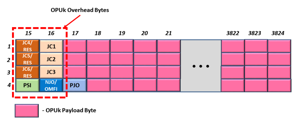
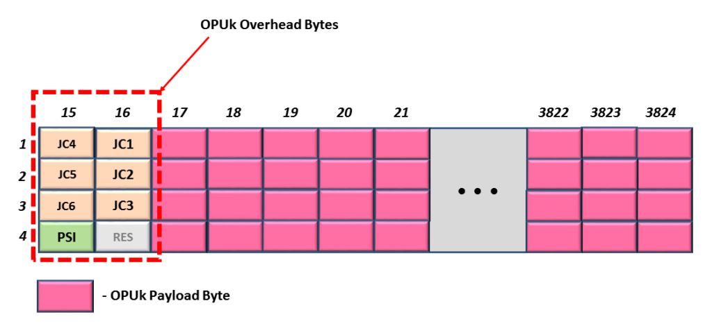
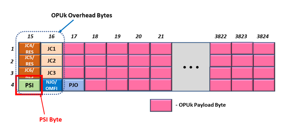
If we are dealing with an OPU4 frame, the OMFI field will reside within the OPU4 Overhead in Row # 4 and Column Byte # 16.

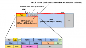
Figure 1 shows a drawing of an OPU4 frame in which we highlight the location of the OMFI field.

OMFI Location
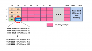
Figure 1, Location of the OMFI field within the OPU4 Frame

The OMFI field does not exist in OPUk frames for any other rates.  The OMFI field only exists within the OPU4 frame.

In other words, OPUflex, OPU0, OPU1, OPU2, OPU2e, and OPU3 frames will NOT have an OMFI field.

When would we use the OMFI field?

We will only use the OMFI field if mapping/multiplexing some lower-speed ODUj tributary signals into an OPU4 server signal.

In other words, we would use the OMFI field if we wish to perform any of the following mapping/multiplexing operations:

  • 80 ODU0 tributary signals into an OPU4
  • 40 ODU1 tributary signals into an OPU4
  • 10 ODU2 (or ODU2e) tributary signals into an OPU4
  • 2 ODU3 tributary signals into an OPU4
  • Various combinations of rates/number of ODUflex tributary signals into an OPU4 server signal

Further, we can also use the OMFI field if we are mapping/mapping multiple combinations of rates of ODUflex signals along with the appropriate number of other ODUj tributary signals (where j can be 0, 1, 2/2e, or 3) into an OPU4 server signal.

NOTE:  We do NOT use the OMFI field if we map some non-OTN client signals (such as 100GbE/100GBASE-R) into an OPU4 signal.

So What does the OMFI field do?

The OMFI field is a byte-wide counter that counts from 0 to 79 and then overflows back to 0 repeatedly.

More specifically, a piece of OTN Network Equipment (e.g., the Source PTE) will (at some point) transmit an OPU4 frame with the OMFI field set to the value “0x00”.

When the Source PTE transmits the next OPU4 frame, it will set its OMFI byte-field to 0x01.   The Source PTE will increment the value that it writes into the OMFI byte-field within each OPU4 frame it generates and transmits.  

Eventually, the Source PTE will transmit an OPU4 frame with the OMFI field set to the value 0x4F (which is the number 79 in decimal format).

Afterward, when the Source PTE transmits the next OPU4 frame, it will set the OMFI field back to 0x00, and it will continue to send another set of 80 consecutive OPU4 frames in this manner, repeatedly.

This means that the OTN network can (and does) use the OMFI field to group 80 consecutive OPU4 frames into an OPU4 Superframe.

We will discuss these OPU4 Superframes later on in this post.

Clueless about OTN? We Can Help!!! Click on the Banner Below to Learn More!!!

Corporate Discounts Available!!!

Why can’t we use the MFAS field for OPU4 Applications?

This is a good question.

The MFAS field (like the OMFI field) is a byte-wide counter.  The behavior and function of these two bytes are very similar.

NOTE:  Please see the OTUk Post for more information about the MFAS field.

The Source STE increments the value within the MFAS byte as it transmits each new OTUk frame.

However, the OMFI byte-field only counts from 0 to 79, and then it overflows back to 0 and then repeats the process.

The MFAS byte counts from 0 to 255, overflows back to 0 and then repeats the process indefinitely.

The MFAS field is convenient for grouping 256 consecutive OTUk/ODUk/OPUk frames into a 256-frame Superframe.

It is also suitable for grouping 4, 8, 16, and 32 consecutive OPUk frames in smaller Superframes. 

NOTE:  We use the MFAS byte when mapping/multiplexing lower-speed ODUj tributary signals into ODU1, ODU2, or ODU3 server signals.  

In short, the MFAS is great for grouping OPUk frames into Superframes with sizes of 2n consecutive OPUk frames (e.g., 22 = 4, 23 = 8, 24 = 16, 25 = 32, and so on).

However, no integer value for n (within the expression 2n) will give you a value of 80.

Thus, if I want to group 80 ODU4 frames into an ODU4 Superframe, the MFAS byte is useless for that purpose.

We need a different byte for this role.  This is why we have the OMFI byte field.

Would we use the OMFI field for the AMP (Asynchronous Mapping Procedure)?

In a word, “No.”

When mapping client signals into an ODU4 server signal, we will ONLY use the GMP (Generic Mapping Procedure).

We never use AMP to map client signals into an OPU4 payload.  This is NOT allowed per ITU-T G.709.

NOTE:  This statement is true, whether we are mapping non-OTN client data (such as 100GBASE-R) or lower-speed ODUj tributary signals into an OPU4 signal.

To be clear, we can use AMP to map client signals into OPU1, OPU2, and OPU3 server signals but not into an OPU4 server signal.

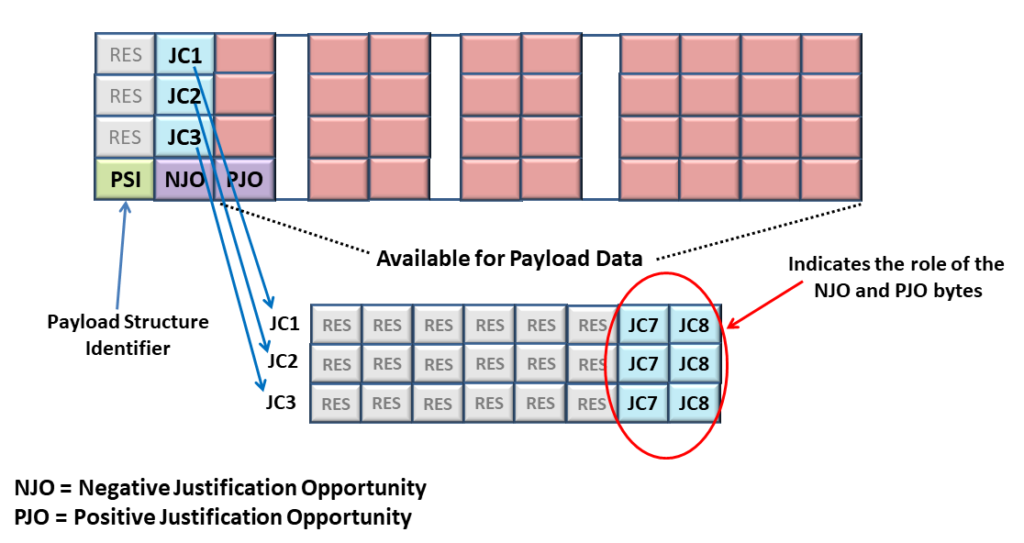
This is a good trick question, however.

This is a trick question because if we were using AMP to map client data into an OPUk frame, then the NJO (Negative Justification Opportunity) byte would occupy the same byte position that the OMFI field occupies for OPU4 applications.

NOTE:  Please see the AMP (Asynchronous Mapping Procedure) post for more information on the NJO byte.

How do we use the OMFI field in a system application?

Let’s assume we wish to map and multiplex 80 ODU0 tributary signals into an OPU4 server signal.

If we want to do this, ITU-T G.709 states that we should perform this mapping/multiplexing in a five-step process.

  • Convert each ODU0 signal into an Extended ODU0 signal.
  • Use GMP to map each of the 80 ODU0 signals into their ODTU4.1 structure/signal.  This step will create 80 ODTU4.1 signals.
    • As we perform this task, we will create 80 sets of GMP Mapping parameters that we will load into the Overhead Portion of 80 sets of ODTU4.1 frames.  
  • Byte interleaves all 80 of the payload portion of these ODTU4.1 signals together into a single data stream.
  • Load this byte-interleaved ODTU4.1 payload data into the OPU4 payload within each outbound OPU4 frame.
  • Load the GMP mapping parameters (within the ODTU4.1 Overhead) into the OPU4 overhead.  

Please see the Extended ODUj Post for more details on the Extended ODU0 signal.

What is an ODTU4.1 Frame/Signal?  

The standards define the ODTU4.1 as Optical Data Tributary Unit (for an OPU4/ODU4 server signal) with 1 (one) Time-Slot.

For this post, I will state that the ODTU4.1 structure/signal is an intermediate frame/signal (defined in ITU-T G.709). 

We only use this frame/signal whenever mapping/multiplexing ODU0 tributary signals into an OPU4 signal.

We present a more thorough description of the ODTU4.1 structure in another post.

Figure 2 shows a drawing of a Mapper Circuit that performs this two-step Mapping/Multiplexing Process.

ODU0 to OPU4 Mapper Circuit

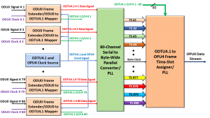
Figure 2, Illustration of an 80 ODU0 Signal to OPU4 Mapper Circuit

Whenever we GMP map a given ODU0 signal into an ODTU4.1 structure, the Mapper circuit will compute the resulting GMP parameters for this single mapping operation.

What’s the Deal with the Number 80?

Since we individually map each of the 80 ODU0 tributary signals into their ODTU4.1 structure, and since each of the 80 ODU0 signals CAN be asynchronous to the remaining 79 ODU0 signals, there will be 80 unique sets of GMP mapping parameters within this OPU4 signal.

The ODU0 to OPU4 Mapper circuit will need to insert each of these 80 sets of GMP parameters into the OPU4 data stream to provide the OPU4 to ODU0 De-Mapper circuit (at the remote Sink PTE) with the GMP Justification Control information that it needs to be able to properly de-map out each of the ODU0 tributary signals from their ODTU4.1 signal.

Has Inflation got You Down? Our Price Discounts Can Help You Fight Inflation and Help You Become an Expert at OTN!!! Click on the Banner Below to Learn More!!!

Discounts Available for a Short Time!!!

So, where does the Mapper Circuit insert the GMP parameters (for all 80 ODU0s) into the OPU4 Frame?

I mentioned earlier that when mapping lower-speed ODUj tributary signals into an OPU4 signal, we execute this procedure by creating an 80 OPU4 frame Superframe.

In other words, as we map and multiplex these 80 ODU0 signals into the OPU4 signal, we will also create these 80 OPU4 frame Superframes.

In the OPU Post, I stated that each OPUk frame consists of an OPUk Payload and OPUk Overhead.

Thus, an 80 OPU4 frame Superframe will contain 80 sets of OPU4 payload and will also include 80 sets of OPU4 overhead.

Please note that each of these OPU4 Superframes contains 80 frames and we are trying to map 80 ODU0s into an OPU4 is NOT a coincidence.

This was all done by design.

ITU-T G.709 states that an ODU0 to OPU4 Mapper circuit should insert the GMP parameters (that we obtained when we GMP mapped ODU0 # 1 into its ODTU4.1 frame/signal) into the JC1 through JC6 bytes within the Overhead of OPU4 Frame # 1 (within the 80 OPU4 Frame Superframe).

Likewise, the standard also states that the Mapper should insert the GMP parameters (we obtained when we mapped ODU0 # 2 into its ODTU4.1 frame/signal) into the JC1 through JC6 bytes within the Overhead of OPU4 Frame # 2.

This process should continue to OPU4 Frame # 80.

At this point, the ODU0 to OPU4 Mapper circuit has completed its transmission of an 80 OPU4 Frame Superframe, and it should start transmitting a new Superframe by sending OPU4 Frame # 1 again (and so on).

But How Do We Know Which OPU4 Frame is OPU4 Frame # 1, # 2, and so on?

The short answer is the contents of the OMFI byte of each of these OPU4 frames.

Whenever the OMFI byte (within a given OPU4 frame) is set to “0x00”, we can state that this particular OPU4 Frame is the first frame in the 80-frame Superframe.

Hence, we can designate this frame as OPU4 Frame # 1.

Likewise, whenever the OMFI byte (within a given OPU4 frame) is set to “0x01”, we can state that this particular OPU4 frame is the second frame in the 80-frame Superframe.

Thus, we can designate this frame as OPU4 Frame # 2, and so on.

We Use the OMFI Byte to Identify Each of these 80 OPU4 frames.

Therefore, if the Sink PTE (at the remote end) receives an OPU4 frame, in which the OMFI byte is set to “0x00”, then we know the following things about the overhead data within that frame.  We understand that the data (within the JC1 through JC6 bytes) will contain the GMP parameter data we obtained when the Source PTE mapped ODU0 # 1 into its ODTU4.1 frame/signal.

Likewise, if the Sink PTE receives an OPU4 frame, in which the OMFI byte is set to “0x01”, we know the following about the overhead data within this frame.  We understand that the data (within the JC1 through JC6 bytes) will contain the GMP parameter data we obtained when the Source PTE mapped ODU0 # 2 into its ODTU4.1 frame/signal.

And so on, for the remaining 78 frames within this OPU4 frame Superframe.  

Figure 3 presents an abbreviated drawing of an 80 OPU4 Frame Superframe.

This figure also shows some helpful information about the contents of the Overhead data within each of the OPU4 frames. 

More specifically, this drawing also identifies which ODU0 to ODTU4.1 frame GMP mapping operation these overhead fields pertain to within each OPU4 frame.

80 OPU4 Frame Superframe

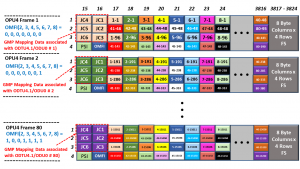
Figure 3, Illustration of an 80 OPU4 Frame Superframe

For example, for OPU4 Frame 1, some red text states the following:  “GMP Mapping Data associated with ODTU4.1/ODU0 # 1″. 

This text means that the six Justification Control bytes (e.g., the JC1 through JC6 byte – in the Pink Fields) contain the GMP mapping parameters that the Source PTE generated when it GMP mapped ODU0 # 1 into ODT4.1 signal # 1.    

This is handy information for the Sink PTE.  

So what does the De-Mapper Circuit do?

As the De-Mapper circuit (within the remote Sink PTE) receives and processes these OPU4 frames, it will need to execute the following two-step procedure to properly de-map and recover these ODU0 tributary signals from this incoming OPU4 data stream.

  • Byte de-interleaves the OPU4 payload data into 80 parallel streams of these ODTU4.1 signals.
  • Use GMP to de-map each ODU0 signal from their ODTU4.1 signal (e.g., de-map 80 ODU0 signals out of 80 ODTU4.1 signals)

I show an illustration of an OPU4 to 80 Channel ODU0 De-Mapper circuit below in Figure 4.

OPU4 to ODU0 De-Mapper Circuit

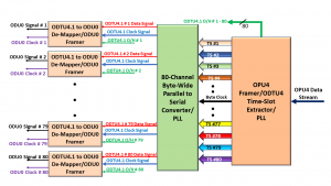
Figure 4, Drawing of an OPU4 to 80 Channel ODU0 De-Mapper Circuit

De-Mapping the ODU0 Signal from Each ODTU4.1 Signal

However, for the de-mapper circuit (within the Sink PTE) to do this successfully, it will need to have the correct GMP mapping parameters that the Source PTE created at the remote end. 

In other words, for the Sink PTE to de-map out ODU0 # 1 from ODTU4.1 signal # 1, it will need to have the same GMP mapping parameters that the Source PTE (at the remote end) generated when it mapped ODU0 # 1 into ODTU4.1 signal # 1, in the first place.  

Likewise, for the Sink PTE to de-map out ODU0 # 2 from ODTU4.1 signal # 2, it will need to have the same GMP mapping parameters that the Source PTE (again, at the remote end) generated when it mapped ODU0 # 2 into ODTU4.2 signal # 2.  

The Sink PTE will receive 80 sets of GMP mapping parameters within each 80 Frame OPU4 Superframe.  

How does the Sink PTE know which (of the 80) GMP mapping parameters to use if we wish to de-map out ODU0 # 1 from ODTU4.1 signal # 1?  

Answer:  It needs to use the overhead data within the OPU4 frame, in which the OMFI byte is set to 0x00.

Thus, the de-mapper circuit must rely on the OMFI value to keep this information straight.

In other words, the Sink PTE will use the OMFI byte to properly marry up each of the 80 GMP mapping parameters (within the incoming OPU4 data stream) with 80 ODTU4.1 data streams.  

Hence, using the OMFI byte, the Sink PTE will be able to correctly de-map out all 80 ODU0 signals from each of their ODTU4.1 signals that we extract from the incoming OPU4 data stream.  

Does ITU-T G.798 Define any Defects that Pertain to the OMFI field?

Yes, ITU-T G.798 does define the dLOOMFI (Loss of OMFI Synchronization) defect for applications in which we are mapping and multiplexing lower-speed ODUj signals into an OPU4/ODU4 signal.

I discuss how ODU-Layer circuitry will declare and clear the dLOOMFI defect condition within Lesson 10 of THE BEST DARN OTN TRAINING PRESENTATION…PERIOD!!!

Summary and Other Related Postings

This post describes the OMFI field (within the OPUk frame) and how we use it whenever we are mapping and multiplexing 80 ODU0 signals into an OPU4/ODU4 signal.  We also have similar postings (on the OMFI field) for the following cases.

Clueless About OTN? We Can Help!! Click on the Banner Below to Learn More!!!

Discounts Available for a Short Time!!!

For More Information on OTN Posts in this Blog, click on the Image below.

OTN Related Blog

OTN Related Topics within this Blog

OTN Related Topics within this Blog General Topics Consequent Equations - What are they and How can you use them? ...

What are some OTN Mapping Procedures?

This post briefly lists and describes the various mapping procedures that have defined for OTN applications and specified in ITU-T G.709.


What Mapping Procedures can we use to Map a Non-OTN Client Signal into an OTN Signal?

This post briefly reviews each standard procedure for mapping non-OTN client signals into an OTN (Optical Transport Network) signal.

Other posts discuss these mapping procedures in greater detail.  

Introduction

As the name suggests, OTN (Optical Transport Network) is a transport technology.  The purpose of the OTN is to transport user (or client) data from Point A to Point B.

All this is analogous to a train system that transports passengers from one train station to another.  In this case, the OTN is the “train,” and the client data are the passengers.

The client data can be a wide range of possible signals (or data types). 

For example, it could be 1GbE (1000BASE-X), 8Gbps Fibre Channel (FC-800), 100GbE (100GBASE-R), SONET/SDH signal, or many other possible client signals.  

We can transport each type of client signal (and more) from one location to another via the OTN.

Note that as we discuss the term mapping (in this and other posts on this website), we are NOT talking about the type of map shown in the figure below.

Mapping Client Signals into OPUk/ODUk/OTUk Frames

Whenever we map a client signal into an OTN signal, we map this client signal into the OPUk portion of an OTUk frame.

Additionally, whenever we map a non-OTN client signal into the OPUk portion of an OTUk frame, we will map this client signal into the entire OPUk payload.

NOTE:  We do discuss OPUk and OTUk frames in other postings.

ITU-T G.709 recommends three mapping schemes we can use when mapping a (non-OTN) client data into (or de-mapping client data from) an OPUk.

(*) – Requires Membership of THE BEST DARN OTN TRAINING PRESENTATION TRAINING….PERIOD!!

Each of these mapping procedures will use its form of rate-adaptation (e.g., adapting the client signal rate to that of the OTN signal).

As I mentioned earlier, I discuss each of these mapping procedures in greater detail – in other postings on this blog.

Let’s quickly review each of these mapping procedures below.

BMP – Bit Synchronous Mapping Procedure

  • Requires that the following equation is true:

Client_Data_Bit_Rate = OPU_Payload_Carrying_Bit_Rate + some Fixed Stuffing

  • This equation means that the OPU Payload data clock signal should be phase-locked to the Client data clock signal.
  • BMP offers the best jitter performance for client signals that are de-mapped from OTN.
    • BMP does not impose any variable byte-stuffing that you can have in both AMP (e.g., the justification events) and GMP.   This fact gives BMP slightly better de-mapping jitter performance than AMP and GMP.  

New Comprehensive OTN Training…Available Now. Click on the Banner Below to Learn More!!!

Discounts Available for a Short Time!!!

AMP – Asynchronous Mapping Procedure

  • AMP does not require that the timing between the Client_Data_Clock and the OPU_Payload_Data_Clock be synchronized (as is necessary for BMP).
  • However, to use AMP, the System Design must ensure that the frequencies of the Client_Data_Clock (of the Non-OTN Client Signal) and the OPU_Payload_Data_Clock signals must be within ±65ppm of each other.
    • In other words, the Client data rate can be slightly slower or faster than the OPUk Payload Carrying data rate.
    • AMP is the only recommended mapping procedure that permits us to map a client signal with a slightly faster nominal bit-rate than the OPUk payload, provided that we do not violate the above-mentioned 65ppm requirement.
  • The OTN terminal accommodates these timing differences by performing negative or positive-justification actions on the Non-OTN client data (at the Byte level)  as it loads the client data into the OPUk Payload.  We are inserting stuff-bytes into or removing stuff bytes from the OPUk payload through these justification actions.  This procedure is somewhat similar to executing Pointer Adjustments in SONET/SDH.
  • De-mapping Jitter Performance for AMP is not as good as that for BMP.  The client data incurs 8 UIp-p of (pre-clock smoothing/jitter attenuation) jitter with each justification (negative or positive stuffing) event.

GMP – Generic Mapping Procedure

  • Requires that the Client bit-rate be less than or equal to the OPUk_Payload bit-rate.
    • In other words, the Client bit rate CANNOT be higher than the OPUk Payload bit rate.
  • GMP does not mandate any synchronization or frequency offset requirements.
    • The bit rate of the Non-OTN client signal can be WAY OFF from that of the OPUk Payload to use GMP.  
    • For example, ITU-T G.709 recommends using GMP to map an STM-1/STS-1 signal (155.52 Mbps) into an OPUO server signal (1.238934310 Gbps).  
  • One of the goals of GMP is to evenly distribute the Payload and Stuff Bytes throughout the OPUk payload to enhance de-mapping jitter performance.
  • I cover GMP mapping in detail in Lesson 4, within THE BEST DARN OTN TRAINING PRESENTATION…PERIOD!!

When to use BMP, AMP, and GMP – per ITU-T G.709

ITU-T G.709 recommends the following mapping procedures for various Client signal types and OTN rates (see Tables 1 through 4 below)

Table 1, ITU-T G.709 Recommended Mapping Recommendations for SDH signals.

Mapping Procedure for SDH (Synchronous Digital Hierarchy) Signals

Table 2, ITU-T G.709 Recommended Mapping Recommendations for Ethernet Signals

Mapping Procedure for Gigabit Ethernet Signals, 1000BASE-X, 10GBASE-R, 40GBASE-R, 100GBASE-R

Table 3, ITU-T G.709 Recommended Mapping Recommendations for Fibre Channel Signals

Mapping Procedure for Fibre Channel Signals

Table 4, ITU-T G.709, Recommended Mapping Recommendations for Misc Signals.

Mapping Procedures for GPON, InfiniBand Signals

Summary

Table 5 summarizes the timing requirements (between the Client Clock Signal and that for the OPUk/ODU clock) that the System Design must comply with before using any of these Mapping Procedures.

Table 5, Mapping Procedure Timing Requirements

Timing Requirements for BMP, AMP and GMP

Has Inflation got You Down? Our Price Discounts Can Help You Fight Inflation and Help You Become an Expert of OTN!! Click on the Banner Below to Learn More!!

Temporary Discount Available Now

For More Information on OTN Posts in this Blog, click on the image below.

OTN Related Blog

OTN Related Topics within this Blog

OTN Related Topics within this Blog General Topics Consequent Equations - What are they and How can you use them? ...