What is an STE for OTN Applications?

This post defines and describes both a Section and Section Terminating Equipment for OTN applications. This post also defines the term: OTUk-SMOH (Section Monitoring Overhead).


What is Section Terminating Equipment (STE) for OTN Applications?

Whenever we discuss the OTN Digital Layers (e.g., the OPUk, ODUk, and OTUk layers), we can group Networking Circuits and Equipment into one of two broad categories.

I will be using these terms throughout various OTN-related posts within this blog.  So, we must have a strong understanding of these terms.

I have devoted this blog post to STE (Section Terminating Equipment).

I have devoted another post to PTE (Path Terminating Equipment).

NOTE:  I discuss STEs and PTEs extensively in Lesson 3 within THE BEST DARN OTN TRAINING PRESENTATION….PERIOD!!!  I also discuss the differences between STEs and PTEs as well.  

What is a Section?

Before we define the term Section Terminating Equipment (or STE), we must first define the word Section as it pertains to an Optical Transport Network (OTN).

For OTN applications, a Section is a single optical link (or span) between two adjacent pieces of networking equipment.

NOTE:  For lower speed applications, one can realize a Section via a Copper Medium (such as CAT5 or CAT6 Cable).

Figure 1 presents a simple illustration of an Optical Transport Network with some boxes labeled PTE and others labeled STE.

Difference between Section Termination Equipment and Path Terminating Equipment

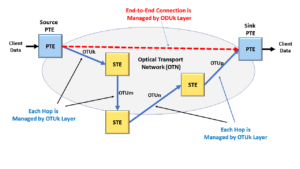
Figure 1 illustrates STE (Section Terminating Equipment) and PTE (Path Terminating Equipment).  Note:  Figure 1 shows a total of five (5) different boxes.  

Two of these boxes are labeled PTE, and three of these boxes are labeled STE.

However, in reality, all 5 of these boxes are STEs.

From a system standpoint, many PTEs are STEs.  However, not all STEs are PTEs.

We can also define a Section as any optical connections connecting these boxes (in Figure 1).

Now, we will define the term Section Terminating Equipment.

What is an STE (Section Terminating Equipment)?

For OTN applications, the basic definition of a Section Terminating Equipment is any equipment that (1) transmits data into or receives data from the Section and (2) also monitors and manages the data transmission over this Section (e.g., the optical fiber link that exists between the Near-End and the adjacent Far-End Network Equipment).

For OTN applications, the OTUk Layer is the protocol layer responsible for managing and monitoring the transmission/reception of data across a Section.

More specifically, an OTN Source (or Transmitting) STE is any equipment that performs ALL the following functions.

The Source STE Operation In the Transmit Direction

  • It will accept data from upstream circuitry (typically in the form of ODUk frames).
  • It electrically preconditions all data (that it is about to transmit to the remote Sink STE via an optical connection) by computing and attaching the OTUk (or OTUkV) overhead to this data stream.  This data will typically (but not always) include the FEC.
  • Once the Source STE has finished preconditioning this data, it will convert this electrical data into the optical format and transmit it over optical fiber to the remote Sink STE.

Sink STE Operation In the Receive Direction

The Sink (Receiving) STE performs all of the following operations.

  • It receives data (from a remote Source STE) in the optical format.
  • The Sink STE then converts this optical data into the electrical format, where it can check and process these newly received OTUk/OTUkV frames.
    As the Sink STE checks and processes this data, it will check for the following items.


  • It will then pass this data to the downstream circuitry as an ODUk data stream (for further processing at the ODUk-layer).

Therefore, if we were to combine our simple definition of the word Section with the description of a Section Terminating Equipment, we can say the following.

Summarizing our Definitions of Section and STE

An STE begins at the point where the Network Equipment (or the Source STE) will precondition and process electrical data in preparation for transmission over an Optical link.

Afterward, the Source STE will convert this signal into the Optical Format, transmitting this optical signal to the remote Sink (or Receiving) STE.

A Section ends (or is terminated) at the point where the Sink STE (that receives this optical signal) converts it back into the electrical format, processes this data, and sends it to downstream equipment.

How the STE Operates in the Optical Transport Network (OTN)

A Source STE will manage and monitor the transmission of this data (across a Section) by encapsulating this data into OTUk/OTUkV frames.

This Source STE will encapsulate this (ODUk) data by generating and inserting some overhead data (that we call the OTUk-SMOH [Section Monitoring Overhead]) into these OTUk/OTUkV frames.

NOTE:  In some of my other posts, I refer to this Source (or Transmitting) STE as the OTUk/ODUk_A_SoOTUk_TT_So, and OTSi/OTUk_A_S0 or OTSiG/OTUk_A_So atomic functions.

The Sink (or Receiving) STE will use this OTUk-SMOH to manage data reception across the Section.

NOTE:  In my other posts, I also refer to this Sink (or Receiving) STE as the OTUk/ODUk_A_Sk, OTUk_TT_Sk, and OTSi/OTUk_A_Sk or OTSiG/OTUk_A_Sk atomic functions.

The STE STE will manage the reception of data across the Section by using this OTUk-SMOH to check for data transmission errors and service-affecting defects.

What is the OTUk-SMOH (Section Monitoring Overhead)?

But when we say “OTUk-SMOH,” what exactly do we mean?

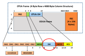
Figure 2 illustrates the OTUk Overhead data (within an OTUk frame) that the Section Terminating Equipment will process and terminate as it manages data transmission across a Section.

This figure also highlights a particular field (regarding Section Monitoring).  This figure highlights the Section Monitoring field.

OTUk Framing Format - Identifying Section Monitoring field

Figure 2, Illustration of an OTUk Frame with the OTUk SMOH Fields highlighted

I highlight the SM (or Section Monitoring) field because the actual OTUk-SMOH (that the Sink STE will use to check for the presence of defects or errors) resides within the Section Monitoring (or SM) field (within the OTUk Overhead).

In Figure 3, I focus on the Section Monitoring field and illustrate the byte format of this 3-byte field.

OTU - SM (Section Monitoring) Field, TTI Byte, BIP-8 Byte, SM Byte

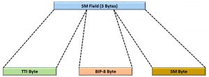
Figure 3, Illustration of the Byte-Format of the Section Monitoring field.

Figure 3 shows that the Section Monitoring field contains the following three byte-fields.

  • The BIP-8 Byte
  • The TTI Byte and
  • The Section Monitoring (or SM) Byte

In Figure 4, I further focus on the SM Byte and show the bit format of that particular byte field.

OTU Frame - Section Monitoring Byte Format - Optical Transport Networks

Figure 4, Bit-Format of the SM (Section Monitoring) Byte – within the Section Monitoring field

If you have seen the OTUk Frame post, Figures 2 through 4 should look familiar.

All of the overheads fields that the Sink STE will need to check for OTUk-related defects and errors (not including FEC) reside within the SM field.

Hence, the OTUk-SMOH is the Section Monitoring field within the OTUk Overhead.

NOTE:  For “nuts and bolts” details on the Source and Sink STEs handling and processing the OTUk-SMOH, check out the posts on the following Atomic Functions.

Now let’s proceed to show an example of STE and its Section.

AN EXAMPLE OF AN STE AND ITS SECTION

Figure 5 illustrates an STE and Section within a typical OTN network connection.

Section Termination Equipment - End-to-End Connection

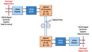
Figure 5, Illustration of the STE and Section (from End to End) in a Typical OTN System

Finally, Figure 5 shows that the Section and STE begin (and end) before and after the OTUk Framer Block.

Please note that the STE also includes the OTUk Framer blocks in this Figure.

The OTUk Framer Blocks (and, in some cases, the OTUk Transceiver Blocks) are responsible for generating and inserting the OTUk-SMOH into the outbound OTUk data stream.

These same functional blocks are also responsible for processing and terminating the OTUk-SMOH within the incoming OTUk data stream.

Throughout numerous blog posts, we discuss the generation and processing of the OTUk-SMOH in detail.

Examples of STE

The following is a list of examples of the various types of OTN STE that are being deployed into the network infrastructure today.

  • Any 3R type of repeater.
  • Any network element that takes electrical data and maps it into an OTUk signal for transport to another terminal over an optical (or copper) connection (e.g., equipment that transmits data through sub-marine links, etc.).
  • CFP Optical Modules that also contains the DSP Transceiver.
  • Line Cards that include CFP2/CFP4 Optical Modules and OTN Framers.

Has Inflation got You Down? Our Price Discounts Can Help You Beat Inflation and Help You Become an Expert on OTN!! Click on the Banner Below to Learn More!!!

Discounts Available for a Short Time!!

For More Information on OTN Posts in this Blog, click on the Image below.

OTN Related Blog

OTN Related Topics within this Blog

OTN Related Topics within this Blog General Topics Consequent Equations - What are they and How can you use them? ...

What is OTUk-BIP-8 or SM-BIP-8?

This post describes the OTUk-BIP-8 (or Section Monitoring BIP-8) value for OTN applications. This post also describes how Networking Equipment both computes and transports this data over a fiber optic connection, as well as how Networking Equipment checks and identifies data transmission errors through the SM-BIP-8 parameter.


What is the OTUk-BIP-8 or Section Monitor (SM-BIP-8) Parameter, and How Do We Compute and Verify it?

This post will define and describe the SM-BIP-8 (Section Monitoring – Bit Interleaved Parity – 8 bit) parameter.

  • In particular, we will describe how the OTN uses this parameter to perform error detection at the OTUk layer.
  • Secondly, we will describe how a Transmitting OTUk Network Element (or a Source Section Terminating Equipment) computes and inserts the SM-BIP-8 Value into the OTUk data stream.
  • Third, we will describe how a Receiving OTUk Network Element (or a Sink Section Terminating Equipment) computes and verifies the SM-BIP-8 Value to check for data transmission errors.
  • Finally, we will discuss the results that a Receiving OTUk Network Element will come up with whenever it does compute and verify the SM-BIP-8 byte value.

NOTES: 

  1. From this point on, I will refer to the Transmitting OTUk Network Element as the Source STE (or Section Terminating Equipment).  I will also refer to the Receiving OTUk Network Element as the Sink STE.
  2. We discuss the SM-BIP-8 field extensively in Lesson 9 within THE BEST DARN OTN TRAINING PRESENTATION…PERIOD!!!

Introduction

For OTN applications, the OTUk layer supports Error Detection and Correction through two means.

  • FEC – Forward Error Correction and
  • BIP-8 – Bit Interleaved Parity – 8 bits

FEC is an Error Detection and Error-Correction scheme discussed in another post.

BIP-8 is purely an error-detection scheme.  It does not support any error correction capabilities.

The OTUk, ODUk, and Tandem Connection Monitoring layers use the BIP-8 error detection scheme.

In this post, we will discuss (what we call) the SM-BIP-8 (Section Monitoring – Bit Interleaved Parity – 8 bits) scheme for the OTUk layer.

NOTE:  We refer to this error detection scheme as SM-BIP-8  (Section Monitoring – Bit Interleaved Parity – 8 bits) because this is the detection scheme that OTN Equipment would employ over a Section via STE (or Section Terminating Equipment).

Please see the post on Section Terminating Equipment for more information on this.

In another post, we discuss the PM-BIP-8 (Path Monitoring – Bit Interleaved Parity – 8 bits) scheme for the ODUk layer.

NOTE:  In this post, we will interchangeably use the terms BIP-8, OTUk-BIP-8, and SM-BIP-8.

So How does the OTN use the SM-BIP-8 scheme?

In every connection between any two adjacent pieces of Networking Equipment, there is an entity that transmits data (e.g., the Source STE), and there is also an entity that receives that data (e.g., the Sink STE).

In most cases, two adjacent pieces of Networking Equipment will also be communicating with each other in a bi-directional manner.

This means that every piece of Network Equipment will transmit and receive data.  This also means that every piece of Network Equipment will contain both a Source STE and a Sink STE.

For OTN application, any time a Source STE transports data to another Network Element via optical fiber or a copper medium, it must encapsulate this data into a series of back-to-back OTUk frames.

Please see the post on OTUk frames to learn more about the OTUk frame structure.

Brief Overview – How the Source STE creates and transports the SM-BIP-8 Byte Value

As the Source STE encapsulates its outbound (client and ODUk) data into a series of OTUk frames, it will perform various functions.

  • It will compute and append the FEC field to the back-end of each outbound OTUk frame.
  • It will compute and insert the SMOH (Section Monitoring Overhead) into each outbound OTUk frame.  In particular, the Source STE will
    • Insert the Trail Trace Message bytes into the TTI byte-field
    • Set the BDI (Backward Defect Indicator) and IAE (Input Alignment Error) bit-fields to the appropriate values (depending upon Network Conditions)
    • Set the BEI/BIAE nibble-field to the appropriate Value (depending upon Network Conditions).

Finally, the Source STE will compute an SM-BIP-8 value for each outbound OTUk frame.

Whenever the Source STE computes the SM-BIP-8 byte value, it will do so by performing a specific type of parity calculation over much of the data within the OTUk frame.

Afterward, the Source STE will insert this SM-BIP-8 byte value into the SMOH (Section Monitoring Overhead) within each outbound OTUk frame.

The Source STE will transport this data (e.g., the OTUk frame data and the SM-BIP-8 Value) over optical fiber to the remote Sink STE.

Brief Overview – How the Sink STE Receives and Processes the SM-BIP-8 byte Values

The Sink STE will accept and process this continuous stream of incoming OTUk frames that it is receiving from the remote Source STE.

As it processes this OTUk data stream, it will verify the SM-BIP-8 byte value within each OTUk frame it receives from the (Remote) Source STE.

The Sink STE verifies this data to check for any transmission errors that might have occurred as these OTUk frames travel from the (Remote) Source STE to the (Near-End) Sink STE.

As the Sink STE verifies this data, it will perform the same parity calculations on the data within the OTUk frames as the (remote) Source STE.

Afterward, the Sink STE will compare its “Locally-Computed” SM-BIP-8 byte value with that computed by the (remote) Source STE.

If the two values for the SM-BIP-8 byte match, then we can state that the Sink STE received the corresponding OTUk frame error-free.

On the other hand, if the two values for SM-BIP-8 do not match, then we know that the Sink STE has detected at least a one-bit error within this particular OTUk frame.

The Details – How does the Source STE generate the SM-BIP-8 Value?

Now that we have the Brief Introductory material out of the way, let’s discuss this in greater detail.

In this section, we will describe the following:

  • Exactly how the Source STE computes the SM-BIP-8 byte value, and
  • How it inserts this SM-BIP-8 byte into the OTUk data-stream, as it transmits this data to the remote Sink STE.  

The Source STE and Introduction to the OTUk_TT_So Atomic Function

ITU-T G.798 refers to the Source STE, which is responsible for (among other things) computing and inserting the SM-BIP-8 Value into the OTUk SMOH as the OTUk_TT_So (OTUk Trail Termination Source) atomic function.

Please see the post on the OTUk_TT_So function to learn more about this atomic function.

NOTE:  We will use the terms Source STE and the OTUk_TT_So function interchangeably throughout this post.

How do we perform a BIP-8 (Bit Interleaved Parity – 8 Bit) Calculation?

The OTUk_TT_So function will compute the SM-BIP-8 Value (for a given OTUk frame) over the data that resides within the OPU portion of that outgoing OTUk frame (e.g., byte-columns 15 through 3824).

Figure 1 presents an illustration that identifies that portion of the OTUk frame that the OTUk_TT_So function will use to perform the BIP-8 Calculations.

Section Monitoring BIP-8 Calculation Region
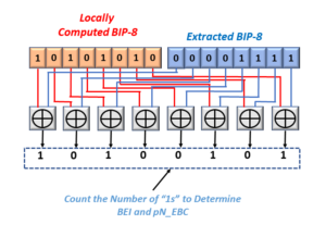
Figure 1, Illustration of that portion of the OTUk frame, which the OTUk_TT_So function will use for the Section Monitoring BIP-8 Calculation  

NOTE:  The OTUk_TT_So function will also include the OPU Overhead within these BIP-8 calculations.

This also means that the OTUk_TT_So function will compute the BIP-8 Value (4 x 3,810 =) 15,240 bytes within each outbound OTUk frame.

The OTUk_TT_So function will compute the BIP-8 Value over this 15,240-byte structure by effectively stacking all 15,240 bytes in a single byte-wide column, similar to what we show below in Figure 2.

Section Monitoring - OTUk BIP-8 Calculation Procedure

Figure 2, Illustration of How the OTUk_TT_So function computes the BIP-8 Value

Figure 2 shows that the OTUk_TT_So function has (effectively) created a 15,240 row by an 8-bit column data structure.

The OTUk_TT_So function will then parse through each of the 8-bit columns within this data structure and compute the EVEN parity value for each of these bit-columns (over 15,240 bits).

Since there are 8-bit columns, the OTUk_TT_So function will compute eight individual EVEN parity bits (one for each bit-column).

This resulting set of the 8 EVEN parity bits is the SM-BIP-8 byte value for this particular OTUk frame.

This procedure describes how we perform a BIP-8 calculation over a block of data (such as the OPUk-portion of an OTUk frame).

How does one Source STE transport the SM-BIP-8 to another Network Element?

The OTUk_TT_So function will then take this BIP-8 byte value and insert it into the SM-BIP-8 byte field within the Section Monitoring field of the outbound OTUk frame, two frame periods later, as we show below in Figure 3.

Section Monitoring BIP-8 Calculation and Insertion Region

Figure 3, Illustration of How the OTUk_TT_So function inserts the SM-BIP-8 byte values into the OTUk data-stream  

The OTUk_TT_So function adds this 2-frame delay to give the Sink STE (at the remote terminal) enough time to compute and verify the SM-BIP-8 byte value (at its end).

Figures 4 and 5 together present the exact location of the SM-BIP-8 byte-field within each outbound OTUk frame.

Figure 4 illustrates the OTUk frame format, with the Section Monitoring (SM) field highlighted.

Location of Section Monitoring Field within OTUk Frame

Figure 4, Illustration of the OTUk Frame with the Section Monitoring (SM) field highlighted

And Figure 5 presents an illustration of the Section Monitoring (SM) field with the SM-BIP-8 byte-field highlighted.

Location of BIP-8 Byte within Section Monitoring Field

Figure 5, Illustration of the Section Monitoring (SM) field, with the BIP-8 byte-field highlighted

The OTUk_TT_So function will transmit this OTUk data stream (along with the locally-computed SM-BIP-8 byte value) to the remote terminal equipment.

We will discuss below how the Remote Sink STE receives and processes these OTUk frames and their SM-BIP-8 values.

New Comprehensive OTN Training…Available Now. Click on the Banner Below to Learn More!!!

Discounts Available for a Short Time!!!

What does the Sink STE do with the SM-BIP-8 Value?

The Sink STE performs the exact opposite role, as does the Source STE.

The Sink STE and Introduction to the OTUk_TT_Sk atomic function

ITU-T G.798 refers to the entity that (among other things) computes and verifies the SM-BIP-8 byte values (for each OTUk frame) as the OTUk_TT_Sk (OTUk Trail Termination Sink) atomic function.

Please see the post on the OTUk_TT_Sk function to learn more about this atomic function.

NOTE:  We will use the terms Sink STE and OTUk_TT_Sk function interchangeably throughout the remainder of this post.

I stated earlier that the OTUk_TT_Sk function has the exact opposite role, as does the OTUk_TT_So function.

The OTUk_TT_Sk function verifies the SM-BIP-8 byte value for each OTUk frame it receives from the remote Source STE (OTUk_TT_So Function).

Once again, the purpose of having the OTUk_TT_Sk function check and verify the SM-BIP-8 byte values is to check for the occurrence of bit errors within the OTUk data stream as it travels from the OTUk_TT_So function (within the Source STE), across optical fiber, to the OTUk_TT_Sk function (within the Sink STE).

Figure 6 presents a simple illustration of an OTUk_TT_So function transporting this OTUk data stream to the OTUk_TT_Sk function at the remote terminal.

OTUk_TT_So to OTUk_TT_Sk unidirection connection

Figure 6, Illustration of the OTUk_TT_So function transporting an OTUk data-stream to the OTUk_TT_Sk function (at the remote terminal)

For your reference,  the circuitry (that I show above) in Figure 6 is functionally equivalent to the Network Element connections I show below in Figure 7.

Basic Network Element WEST connected to Network Element EAST bidirectionally over Fiber Optic connection

Figure 7, Illustration of the Equivalent Circuitry (in Figure 6), expressed at the Network Element Layer.  

We will describe how the OTUk_TT_Sk function computes and verifies the SM-BIP-8 byte value within each incoming OTUk frame.

The OTUk_TT_Sk function computes and verifies these SM-BIP-8 byte values by executing the following two steps to process each OTUk frame it receives.  

  • Step 1 – The OTUk_TT_Sk function will locally compute its SM-BIP-8 byte value for an incoming OTUk frame, and 
  • Step 2 – The OTUk_TT_Sk function will then compare its locally-computed BIP-8 byte value with that which the OTUk_TT_So function (at the Remote STE) inserted into the SM-BIP-8 byte field within the incoming OTUk data-stream.

We will discuss each of these steps below.

STEP 1 – The OTUk_TT_Sk function will locally compute Its sm-BIP-8 byte value for an incoming OTUk frame. 

The OTUk_TT_Sk function will locally compute its SM-BIP-8 byte value for an incoming OTUk frame by performing the same procedure that the OTUk_TT_So function did at the remote terminal (Source STE).

The OTUk_TT_Sk function will take the 15,240 bytes of data (that resides within the OPU portion of the OTUk frame), and it will (effectively) stack this data into a 15,240-row x 8-bit column structure.

Figure 8 (once again) presents a simple illustration of an OTUk frame, with the OPU portion (e.g., that portion of the OTUk frame that we use to compute the BIP-8 Value) highlighted.

Section Monitoring BIP-8 Calculation Region

Figure 8, A Simple Illustration of the OTUk Frame, with the OPU-Portion of the Frame, Highlighted.

And if we were to look at this data differently, Figure 9 presents an illustration of the 15,240 Row by 8-bit column structure that the OTUk_TT_Sk function effectively creates from the OPU portion of each incoming OTUk frame.

Section Monitoring - OTUk BIP-8 Calculation Procedure

Figure 9, Illustration of How the OTUk_TT_Sk Computes the SM-BIP-8 byte value for each incoming OTUk frame

The OTUk_TT_Sk function will then parse through each 8-bit column (shown above in Figure 9) individually and compute the EVEN parity of the contents within each bit-column.

Note that it will perform parity calculations over 15,240 bits of data.

Once the OTUk_TT_Sk function has completed this process over each of the eight bit-columns, it will have an 8-bit expression.

This 8-bit expression is (once again) the SM-BIP-8 byte value for this particular OTUk frame.

After the OTUk_TT_Sk function computes its version of the SM-BIP-8 byte value, it needs to perform STEP 2 (of this BIP-8 Verification Process).

STEP 2 – The OTUk_TT_Sk function will compare its Locally-Computed BIP-8 Value with that inserted into the BIP-8 field (by the OTUk_TT_So function at the remote STE).

Once the OTUk_TT_Sk function reads in the contents of an OTUk frame and locally computes its SM-BIP-8 byte value (for that OTUk frame), it then needs to obtain the Value of the remotely-computed SM-BIP-8 byte-field.

If you recall, earlier in this post, I mentioned that the OTUk_TT_So function (at the remote terminal) would compute the SM-BIP-8 byte value for a given OTUk frame, and then it will insert this BIP-8 Value into the SM-BIP-8 byte-field, two OTUk frames later.

I show this relationship between the OTUk frame (that the OTUk_TT_So function computed the SM-BIP-8 byte value for) and its placement within the OTUk data stream above in Figure 3.

Therefore, the OTUk_TT_Sk function will find this remotely-computed SM-BIP-8 byte value for a given OTUk frame, two (2) OTUk frames later, within the SM-BIP-8 byte-field position.

Once the OTUk_TT_Sk function has obtained these two versions of the SM-BIP-8 byte values, it will then need to compare those two values with each other.

If the two BIP-8 byte-values are equal, then this means that this particular OTUk frame incurred no bit errors during transmission over the optical fiber.

On the other hand, if these two BIP-8 byte values are NOT the same, this particular OTUk frame DID incur bit errors during transmission over optical fiber to the Sink STE. 

In this case, the OTUk_TT_Sk function must determine how many bits (between these two versions of the SM-BIP-8 byte values) are different from each other.

Stated differently, the OTUk_TT_Sk function compares its locally computed SM-BIP-8 byte value and that it reads in from the SM-BIP-8 byte-field within the incoming OTUk data-stream and will perform a bit-by-bit XOR operation with each of these byte values.

The OTUk_TT_Sk function must then count the number of “1s” that occurs during that bit-wise XOR calculation (for each incoming OTUk frame).

The OTUk_TT_Sk function will come up with any one of the following nine (9) possible results.

  • 0 bits in Error – Error-Free Transmission
  • 1 bit in Error
  • 2 bits in Error
  • 3 bits in Error
  • 4 bits in Error
  • 5 bits in Error
  • 6 bits in Error
  • 7 bits in Error
  • 8 (or all) bits in Error

Figure 10 presents a simple illustration of the Bit-Wise XOR Operation that the OTUk_TT_Sk function performs with both the locally-computed and remotely-computed SM-BIP-8 byte values.

BIP-8 Verification Procedure - Bitwise XOR

Figure 10, Illustration of the Bit-Wise XOR Process for Verifying and Comparing the Locally-Computed SM-BIP-8 Byte Value with the Extracted (Remotely Computed) SM-BIP-8 Byte value for a given OTUk frame

The OTUk_TT_Sk function will then need to use the results of these BIP-8 comparisons for the following purposes.

  • To send out the results of these comparisons to the remote terminal in the form of the SM-BEI (Section Monitor – Backward Error Indicator) Value.  Please see the post on SM-BEI to learn more about this topic.
  • It will use these results to determine if the OTUk_TT_Sk function should declare or clear the dDEG (Signal Degrade) defect condition.  (*)
  • To use for Performance Monitoring Purposes (e.g., to compute the pN_EBC parameter in this case).  Please see the post on the pN_EBC  (Near-Error Block Count) Performance Monitor parameter to learn more about this topic.

Will the OTN Network Element ever declare any defects due to excessive SM-BIP-8 errors?

Yes, if the Sink STE were to detect a large number of SM-BIP-8 byte errors over a long period (e.g., typically on the order of seconds), then the Sink STE (or OTUk_TT_Sk Function) can declare the dDEG (Signal Degrade) defect condition.

I describe how the OTUk_TT_Sk atomic function declares and clears the OTUk-dDEG (Signal Degrade) defect condition within Lesson 9 of THE BEST DARN OTN TRAINING PRESENTATION…PERIOD!!

Summary

This post describes the SM-BIP-8 (Section Monitoring – Bit Interleaved Parity – 8 bit) parameter.

At a high level, we have described how the OTN uses this parameter to perform error detection at the OTUk layer.

We have also specifically described how a Source STE computes and inserts the SM-BIP-8 byte value into the OTUk data stream.

We have also described how a Sink STE computes and verifies the SM-BIP-8 byte value (within each incoming OTUk frame) to check for the occurrence of data transmission errors.

Finally, we have identified the results that a Sink STE will come up with whenever it does compute and verify the SM-BIP-8 byte value.  We also mentioned that the Sink STE would use these results to:

Has Inflation got You Down? Our Price Discounts Can Help You Beat Inflation and Become an Expert on OTN!! Click on the Banner Below to Learn More!!!

Discounts Available for a Short Time!!

For More Information on OTN Posts in this Blog, click on the Image below.

OTN Related Blog

OTN Related Topics within this Blog

OTN Related Topics within this Blog General Topics Consequent Equations - What are they and How can you use them? ...