
What is the OSI Reference Model?
The communications/networking industry has defined many standards using a Reference Model.
A Reference Model is an abstract way of looking at the problems of defining and designing a Communications Network.
A Reference Model will divide the design of a Communications Network into many Layers.
For example, many people will use the OSI Reference Model to separate a Communications Network’s design into seven (7) layers.
The OSI (Open Systems Interconnection) Reference Model is defined by the ISO (International Standards Organization).
Figure 1 presents an illustration of the OSI Reference Model.
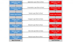
Figure 1, Illustration of the OSI Reference Model
This figure shows that the OSI Reference Model consists of the following layers (when starting from the lowest layer and going to the highest layer):
- The Physical Layer
- The Data Link Layer
- The Network Layer
- The Transport Layer
- The Session Layer
- The Presentation Layer and
- The Application Layer
You can click on each layer name to learn more details about each layer.
Figure 1 shows that the Physical Layer is the lowest-level Layer in the OSI Reference Model, the Data Link Layer is the next (up) from the Physical Layer, and so on.
The Application Layer is the highest in the OSI Reference Model.
Figure 1 also shows two data communication terminals communicating with each other.
This figure illustrates seven (7) blocks or processes within each terminal that support each of these layers’ roles.
There are three basic ideas behind the design and implementation of these layers.
- Independence – The design of one layer should be independent of each of the remaining layers’ design.
- Service – A given layer’s responsibility is to service the next layer above it.
- Supports peer-to-peer Communication – A layer must support peer-to-peer communication between the Layer Controller (or Process) at the Source Terminal and that at the Destination Terminal.
We will discuss each of these concepts below:
Independence
Independence means that the system designer should design each layer to be independent of the other layers’ designs.
For example, the System Designer can choose to use Copper Media (e.g., Coaxial Cable, Twisted-Pair), Optical Fiber (e.g., Multi-Mode Fiber or Single-Mode Fiber), or go wireless.
The designer’s choice for the physical media should not affect the Data Link Layer layer’s design or any of the remaining five (5) higher layers.
In other words, the user should choose one physical media or another, and the design of the Data Link Layer (along with the remaining layers above the Data Link Layer) is not affected by this selection.
Thus, later on, if the user decides to replace the copper media with optical fiber, this engineering change will undoubtedly affect the design of the Physical Layer.
However, this change should not affect the Data Link Layer (or the five higher layers). All these layers should still function similarly, whether using copper, optical fiber, or wireless media.
NOTE: The various reference model standards will each specify a standard interface between these layers.
This standard interface permits a given layer to communicate with the next layer up or below.
For example, the Network and Transport layers have standard interfaces that allow data/information to flow between these two Layers.
Yet reference model standards do not specify how the user realizes the design of a given layer.
Service
The Physical Layer aims to provide a communications service for the Data Link Layer (the next higher layer).
The Data Link Layer (at the source terminal) provides its data to the Physical Layer. The Physical Layer then takes this data and transports it to the destination terminal over the chosen media.
The Physical Layer (at the destination terminal) then receives this data and presents it to the Data Link Layer (also at the destination terminal).
Likewise, the purpose of the Data Link Layer is to provide a communication/error-detection service for the Networking Layer (e.g., the next higher layer), and so on, all the way up to the Application Layer.
We discuss the concept of service in greater detail in “The OSI Reference Model at Work – A Macro View.”
Supports peer-to-peer Communication
Figure 1 illustrates a simple Communications Network consisting of two terminals.
We’ve labeled one of these terminals as the “West Terminal” and the other as the “East Terminal.”
This figure also shows that each terminal contains processes supporting the controller function for these seven (7) layers.
Some of these processes are implemented via hardware design, and some of these other processes are implemented via software code.
For example, the Physical Layer (at each of the terminals) will contain transmitting circuitry (e.g., some circuitry that transmits data from the “Source Terminal” to the “Destination Terminal” over the selected medium).
Likewise, the Physical Layer (at each terminal) will contain receiving circuitry (e.g., some circuitry that receives data from the remote/Source terminal).
This circuitry has been designed to receive data that has traveled over some distance (over the medium of choice) and compensate for any distortion/impairments that the data signal will experience within the media.
We can refer to this particular data transmission as “peer-to-peer” communication between the Physical Layer processes in each terminal.
There is also a similar peer-to-peer communication link between the Data Link Layer processes at each terminal, the Network Layer, and so on (as indicated by the dashed lines between each layer process in both terminals).
We discuss the concept of “peer-to-peer communication” in greater detail in “The OSI Reference Model at Work – A Macro View.”
Other Communication Standards have their Reference Models as well.
- TCP/IP – Transport Control Protocol/Internet Protocol
- SONET
- SDH
- OTN
- PCI Express
You can click on these links to learn more about these Reference Models.
Clueless about OTN? We Can Help!! Click on the Banner Below to Learn More!!!
Discounts Available for a Short Time!!!
