What is the Physical Layer – within the OSI Reference Model?
The Physical Layer is the lowest-level layer within the OSI Reference Reference Model.
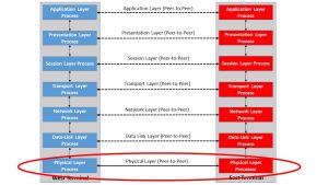
Figure 1 illustrates the OSI Reference Model, with the Physical Layer circled.

Figure 1, Illustration of the OSI Reference Model – with the Physical Layer circled
In short, a Physical Layer design focuses on transmitting a continuous data stream from one terminal to an adjacent terminal.
As far as the Physical Layer is concerned, this data will be in the form of electrical signal pulses and optical or RF symbols – depending upon whether the communication media is copper, optical fiber, or wireless/RF.
Additionally, Physical Layer designs/processes do not pay attention to framing or packet delineation.
The Higher-Layer processes will handle framing and packets. The Physical Layer processes will consider this stream of pulses to be just an unframed raw stream of bits.
Some Terminology
Throughout this blog, we will refer to the entity (e.g., the Transmitter and Receiver) that handles the Physical Layer functions (or processes) as the Physical Layer Controller.
A transceiver is a typical example of a Physical Layer Controller.
Purpose
The purpose of the Physical Layer Controller is to provide a communications service for the local Data Link Layer Controller.
A Physical Layer controller (at a transmitting terminal) will accept data from the local Data Link Layer Controller.
The Physical Layer controller will transmit this data over some medium (e.g., copper, optical fiber, or wireless communication) to a similar Physical Layer Controller at the adjacent receiving terminal.
The Physical Layer Controller (at the receiving terminal) will then provide this received/recovered data to its local Data Link Controller for further processing.
We often refer to this communication between the two Physical Layer controllers as “peer-to-peer communication” between two Physical Layer controllers.
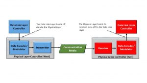
Figure 2 presents a closer look at the physical layer controllers’ role in the transport of data.

Figure 2, A Simple Illustration of the role that the Physical Layer controller plays in the transport of data across a media
Whenever a Physical Layer Controller (at a transmitting terminal) accepts data from the local Data Link Layer controller, it will encode it into some line code or modulation format suitable for the communication media.
Afterward, the Physical Layer controller will transmit this data over the communication media.
The Physical Layer controller (at the receiving terminal) will receive and recover this data from the media.
Additionally, the Physical Layer controller will decode this data (from the line-code or modulation format) back into its original data stream.
The Physical Layer controller will then pass this data to the Data Link Layer controller for further processing.
NOTES:
- Figure 2 is a simple illustration and does not include all possible circuitry within a Physical Layer controller (or Transceiver).
- Please see the post on the Data Link Layer for further insight into how the Data Link Layer handles this data.
Physical Layer Types in various types of Communication Media
The Physical Layer is designed to transport data from a transmitting terminal to a receiving terminal.
The Physical Layer can be designed to transport data over any of the following types of media.
- Copper Medium
- Twisted-Pair
- Coaxial Cable
- Microstrips or Striplines on a High-Speed Backplane
- Optical Fiber
- Multi-Mode Fiber
- Single-Mode Fiber
- Wireless/RF
- Microwave
- Cellular
- Satellite Communication
Physical Layer Design Considerations for Copper Media
For copper media, the Physical Layer will be concerned with the following design parameters
- Line-Code (e.g., Manchester, B3ZS, 64B/66B coding, various forms of scrambling, etc.).
- Voltage Levels of the signal (being transmitted)
- What kind of signal/pulse should a Physical Layer controller generate and transmit to send a bit/symbol with the value of “0”?
- The kind of signal/pulse should a Physical Layer controller generate and transmit to send a bit/symbol with the value of “1”.
- The minimum voltage level the Receiving Physical Layer controller will correctly interpret a given bit (or symbol) as being a “1”?
- What is the maximum voltage level for the Receiving Physical Layer controller to correctly interpret a given bit (or symbol) as being a “0”?
- Impairments in copper media
- Frequency-dependent loss and phase distortion of symbols.
- Reflections
- Crosstalk Noise
- EMI (Electromagnetic Interference).
- What is the maximum length of copper media that we can support?
Physical Layer Design Considerations for Optical Fiber
For an optical fiber, the Physical Layer will be concerned with the following design parameters
- What kind of symbol are we using to transmit a bit with the value of “0”?
- What kind of symbol are we using to transmit a bit with the value of “1”?
- Modulation scheme (e.g., QPSK, 16QAM, PAM4, etc.)
- What wavelength (or set of wavelengths will we use for communication)?
- Will we transport data over single or multiple wavelengths (e.g., Wave-Division Multiplexing)?
- Impairments in Optical Fiber
- Chromatic Dispersion
- Modal Dispersion (for Multi-Mode Fiber only)
- Polarization Mode Dispersion
- What is the maximum length of optical fiber that we can support?
Physical Layer Design Considerations for all Media
The Physical Layer will be concerned with the following design parameters, regardless of the communication media.
- Are we transporting multiple bits via each symbol (e.g., for PAM4, 16QAM, QPSK, etc.)?
- Bit-Timing (Bit Width) or Symbol-Timing (Symbol Width)
- Jitter/Wander Requirements
- Maximum allowable jitter within a transmitted signal
- Maximum jitter tolerance capability of a receiving terminal
- Minimum permissible SNR (Signal-to-Noise Ratio)
- The maximum permitted BER (Bit-Error Rate)
- Error Detection or Error Detection and Correction
- Are we using Forward Error Correction (FEC)?
- We are ensuring a Sufficient number of transitions (in the signal waveform) to permit a CDR (Clock and Data Recovery) PLL (at the receiving terminal) to acquire and maintain lock with the incoming signal.
- Mechanical Issues (such as connector types)
- Whether the communication is Simplex, Half-Duplex, or Full-Duplex Mode.
The Physical Layer in other Standards
Many of the other Reference Models (e.g., OTN, SONET, SDH, and PCIe) also have a Physical Layer.
Other postings will discuss the Physical Layer for each of these Reference Models.
You can access the posting for the Physical Layers of each of these Reference Models by clicking on the links below:
- OTN
- SONET
- SDH
- PCIe

