Introduction
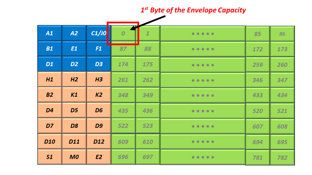
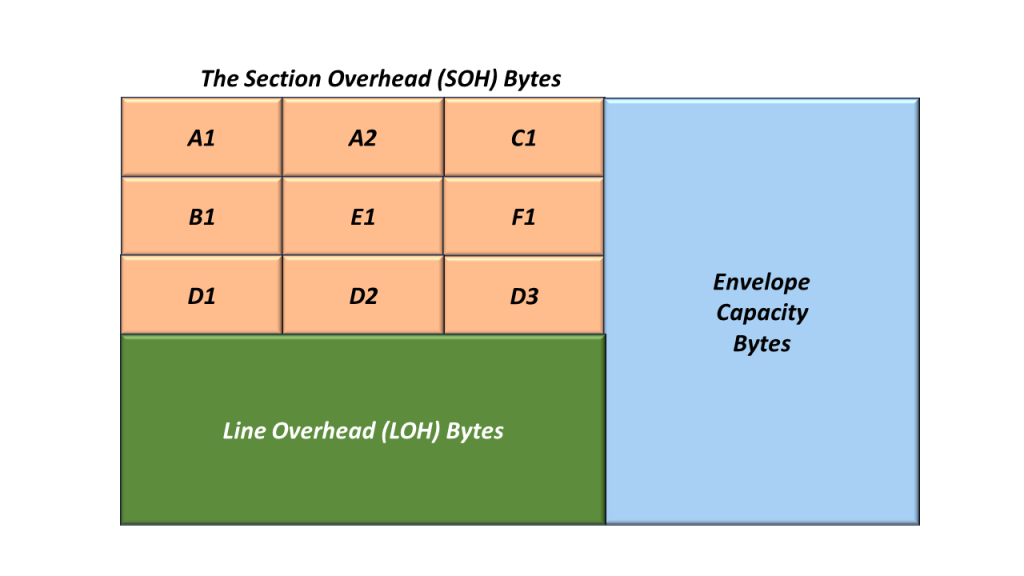
An STS-1 Network Element relies on the A1 and A2 bytes within the Section Overhead (SOH) to acquire and maintain STS-1 Frame Synchronization.
Figure 1 illustrates the Section Overhead bytes with the A1 and A2 bytes highlighted.
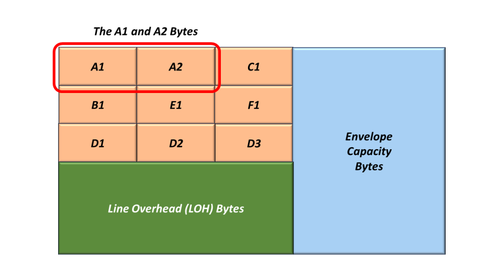
Figure 1, Illustration of the SOH with the A1 and A2 bytes highlighted.
Whenever an STS-1 Transmitter (or STE) generates and transmits an STS-1 frame, it will always set the A1 and A2 bytes to the following values:
- A1 = 0xF6
- A2 = 0x28
I show an additional drawing of SOH, with the values for A1 and A2 filled in.
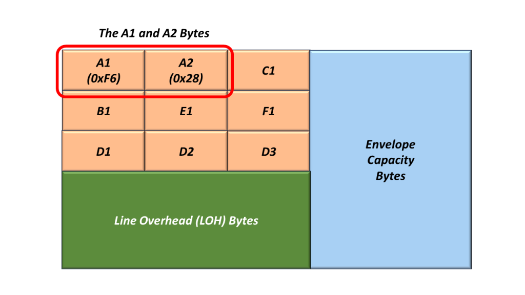
Figure 2, Illustration of the SOH with the A1 and A2 bytes set to their actual values.
Receive STS-1 Framer Tries to Acquire STS-1 Frame Synchronization
The Receive STS-1 Framer (at the remote end of the network – receiving this STS-1 signal) will search for and locate the A1 and A2 bytes (within its incoming STS-1 data stream). As the Receive STS-1 Framer receives this signal, it will attempt to acquire and maintain STS-1 Frame Synchronization with this incoming STS-1 data stream.
A given STE (receiving this STS-1 signal) will declare and clear either of the following defect conditions based on its ability to receive the A1 and A2 bytes.
- dSEF – Severely Erred Frame Defect
- dLOF – Loss of Frame Defect
The SEF/LOF Defect Declaration/Clearance State Machine
The decision to declare and clear the dSEF and/or dLOF Defects is best understood by reviewing the SEF/LOF Defect Declaration/Clearance State Machine Diagram. I show this diagram below in Figure 3.
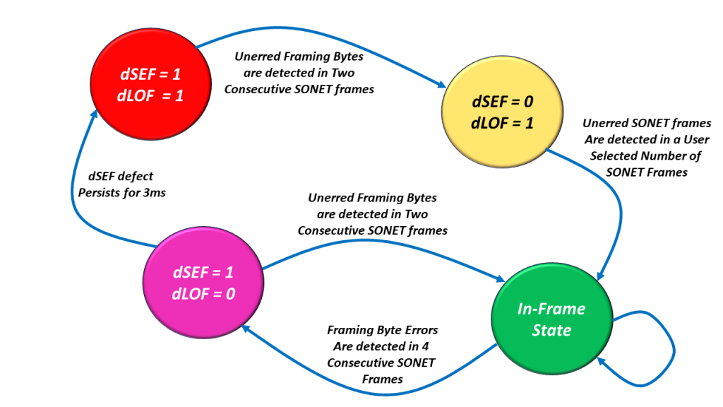
Figure 3, Illustration of the SEF/LOF Declaration/Clearance State Machine Diagram.
You can see that the SEF/LOF Declaration/Clearance State Machine Diagram contains the following four states.
- The In-Frame (or SEF = 0/LOF = 0) State (the Most Desirable State to Operate in).
- The SEF = 1/LOF = 0 State (Declaring the SEF – Severely Erred Frame defect condition).
- The SEF = 1/LOF = 1 State (SONET Framer has not located the A1 and A2 bytes at all), and
- The SEF = 0/LOF = 1 State (The SONET Framer has cleared the SEF defect and is now trying to clear the LOF defect condition).
Let’s Take a Walk through the SEF/LOF Declaration/Clearance State Machine Diagram
Let’s start at the “SEF = 1/LOF = 1” state.
The dSEF = 1/dLOF = 1 State
I show a drawing of the SEF/LOF Declaration/Clearance State Machine Diagram with the SEF = 1/LOF = 1 state highlighted in Figure 4.
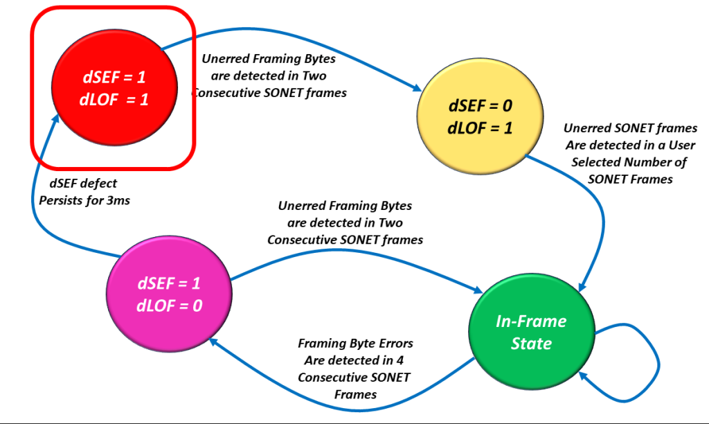
Figure 4, Illustration of the SEF/LOF Declaration/Clearance State Machine Diagram – with the SEF = 1/LOF = 1 state highlighted.
We hope the Receive STS-1 Framer is rarely operating in this state.
Let’s assume (and hope) that the Receive STS-1 Framer only operates in this state upon system power-up. Shortly after power-up, the Receive STS-1 Framer will operate in this state as it receives an STS-1 Data Stream.
As it receives this STS-1 Data Stream, it will parse this incoming data stream and search for the A1 and A2 bytes.
Once it locates (what it believes) are the A1 and A2 bytes (e.g., a string with the value 0xF628), it will note this location and search again exactly 810 bytes (e.g., one STS-1 frame period) later.
At this later period, if it determines that the framing pattern (e.g., 0xF628) is NOT present, then the Receive STS-1 Framer will assume that it was momentarily fooled by data bytes mimicking the A1 and A2 bytes.
On the other hand, if the Receive STS-1 Framer detects the framing alignment pattern again (exactly 810 bytes after finding it the first time), then it will believe that it is on to something and transition into the dSEF = 0/dLOF = 1 state.
NOTE: In this case, the Framer will transition into the dSEF = 0/dLOF = 1 state after the Framer has correctly detected the A1 and A2 bytes in two consecutive STS-1 frames.
The dSEF = 0/dLOF = 1 State
I show a drawing of the SEF/LOF Declaration/Clearance State Machine Diagram with the dSEF = 0/dLOF = 1 state highlighted in Figure 5.
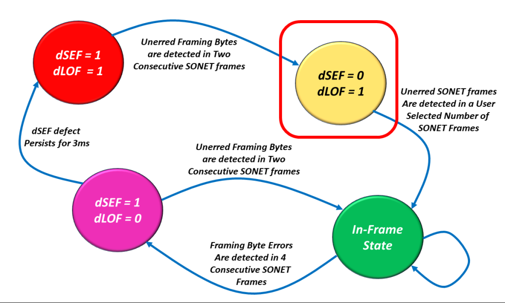
Figure 5, Illustration of the SEF/LOF Declaration/Clearance State Machine Diagram – with the dSEF = 0/dLOF = 1 state highlighted.
Once in this state, the Receive STS-1 Framer block will clear the dSEF (Severely Erred Frame) alarm. It will also continue to check the incoming A1 and A2 bytes for the Framing Pattern.
Telcordia GR-253-CORE states that “the SONET NE shall terminate a LOF defect 1ms to 3ms after terminating the SEF defect on the incoming SONET signal if the SEF defect is not (re) detected before the LOF defect is terminated.”
This is why we labeled the transition (from the dSEF = 0/dLOF = 1 State to the In-Frame State) as “Unerred SONET Frames Are Detected in a User Number of SONET Frames“.
The user can select the criteria for clearing the dLOF defect to be either 1 ms or 3 ms when operating in the dSEF = 0 condition, provided that the dSEF condition is not re-declared during that period.
Either way, if the SONET NE can meet these requirements, it will transition into the In-Frame State.
The In-Frame State
I show a drawing of the dSEF/dLOF Declaration/Clearance State Machine Diagram with the In-Frame state highlighted in Figure 6.
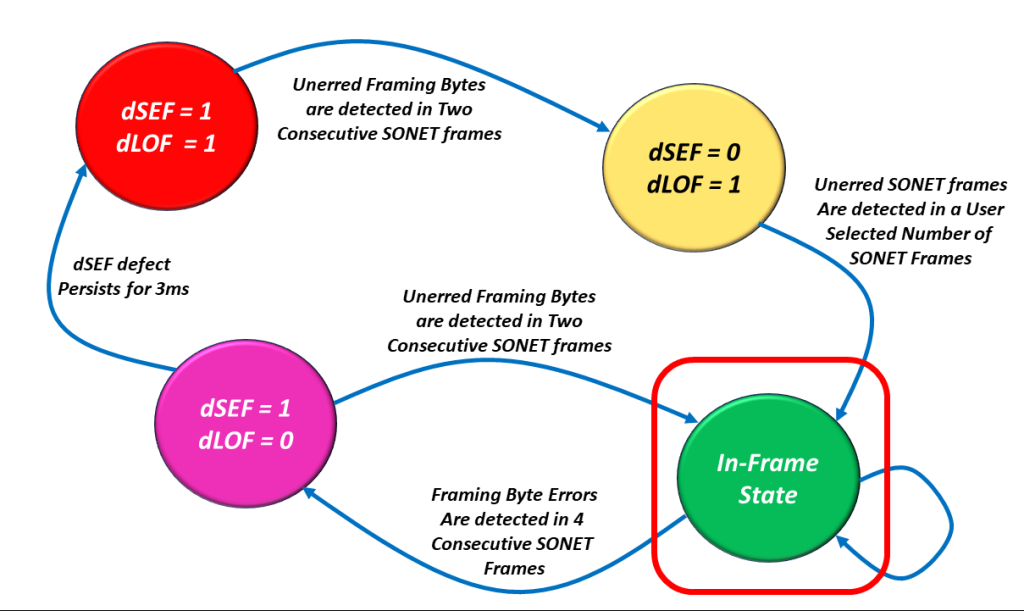
Figure 6, Illustration of the dSEF/dLOF Declaration/Clearance State Machine Diagram – with the In-Frame State Highlighted.
We hope that the Receive STS-1 Framer will operate in this state for most of its lifetime.
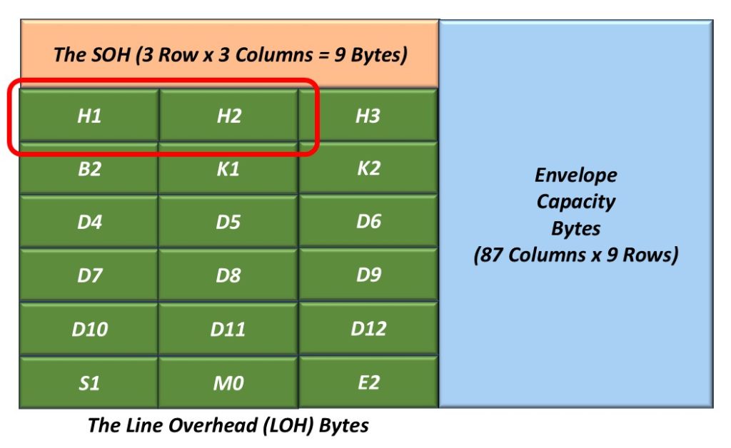
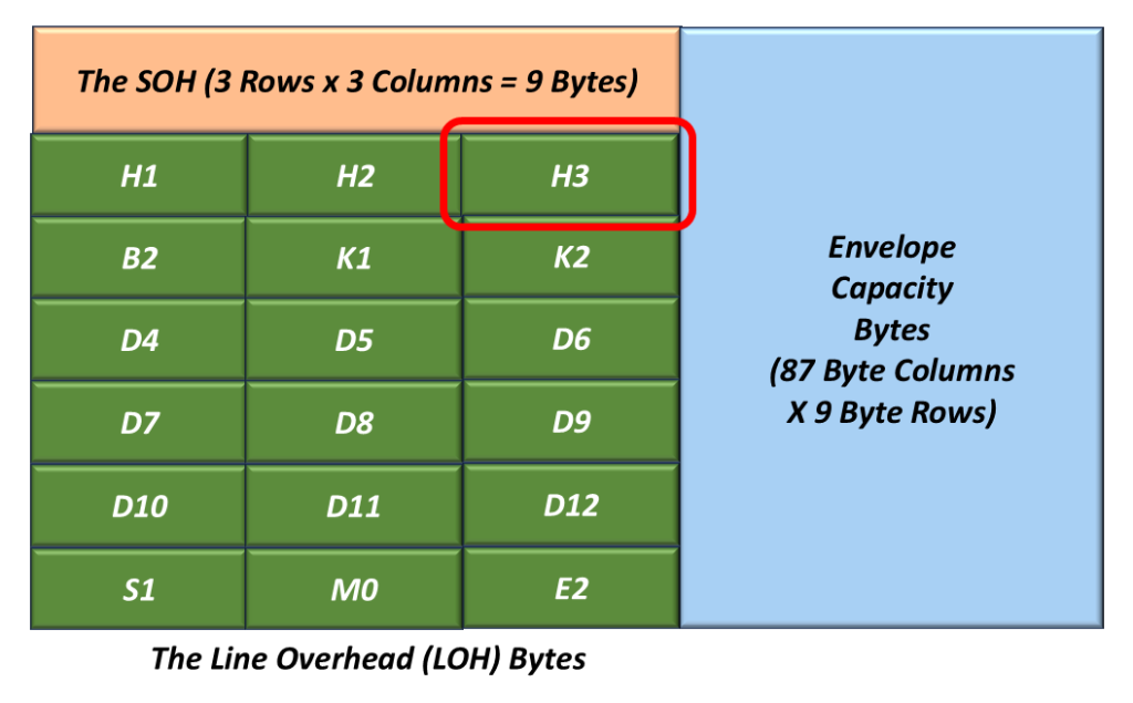
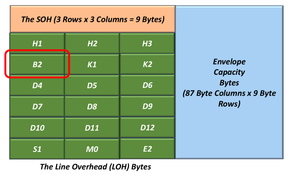
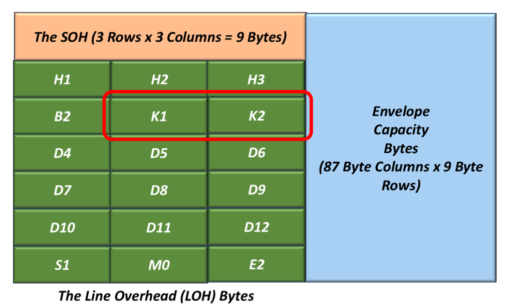
When the Receiver STS-1 Framer circuitry is operating in this state, the SONET NE can now do its other processing of STS-1 frames (checking for B1 bytes errors, using the H1 and H2 bytes to search for the SPE, etc.).
All of these things are possible whenever the Receiver STS-1 Framer is operating in this state. None of these things are possible if the Receiver STS-1 Framer is not operating in this state.
Is it possible for Bad Things to Happen such that We Have to Leave this State?
Yes, all good things can and sometimes do come to an end.
In other words, it is possible for bad things to happen that will cause the Receive STS-1 Framer to leave the In-Frame state.
If the Receive Framer were to detect FA1/FA2 errors within 4 consecutive STS-1 Frame, then it would declare the dSEF defect condition and transition into the dSEF = 1/dLOF = 0 state.
The dSEF = 1/dLOF = 0 State
I show a drawing of the dSEF/dLOF Declaration/Clearance State Machine Diagram with the dSEF = 1/dLOF = 0 state highlighted in Figure 7.
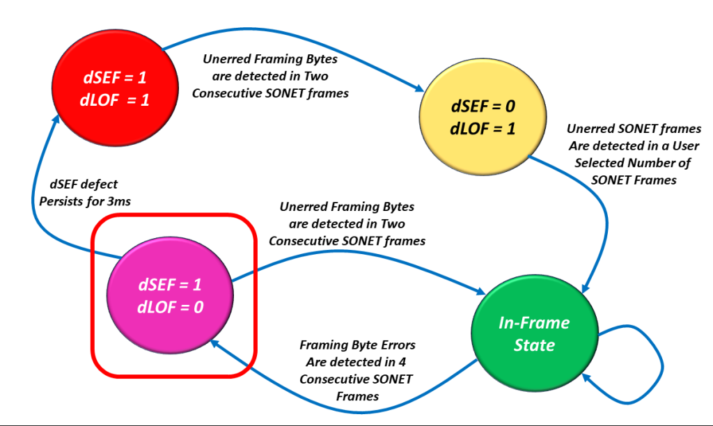
Figure 8, Illustration of the SEF/LOF Declaration/Clearance State Machine Diagram – with the SEF = 1/LOF = 0 State Highlighted.
If the Receive STS-1 Framer transitions into this state, then one of two things can happen from here.
The Good Option
The burst of errors could go away, and the Receive STS-1 Framer block could (then) detect two consecutive STS-1 Framers with NO FA1/FA2 byte errors.
If this occurs, the Receive STS-1 Framer block will clear the dSEF defect and transition back to the In-Frame state, also known as the Good State. Once again, I show a drawing of the dSEF/dLOF Declaration/Clearance State Machine Diagram with the In-Frame state highlighted in Figure 9.

Figure 9, Illustration of the dSEF/dLOF Declaration/Clearance State Machine Diagram – with the dSEF = 0/dLOF = 0 State Highlighted.
And there is the Bad Option.
The Bad Option
The burst of errors persists, and the Receive STS-1 Framer continues to operate continuously in the dSEF Condition for 3 ms. When this occurs, then the Receive STS-1 Framer will declare the dLOF defect, and we will transition back into the dSEF = 1/dLOF = 1 state.
In What States will the Receive STS-1 Framer declare the dLOF Defect Condition?
The Receive STS-1 Framer block will declare the dLOF defect condition whenever it is operating in the following two states:
- dSEF = 1/dLOF = 1
- dSEF = 0/dLOF = 1
In short, whenever dLOF = 1, then the Receive STS-1 Framer block declares the dLOF (Loss of Frame) defect condition.
In What States is the Receive STS-1 Framer NOT declaring the dLOF Defect Condition
The Receive STS-1 Framer block will clear the dLOF defect condition whenever it is operating in the following two states:
- In-Frame
- dSEF = 1/dLOF = 0
In short, whenever dLOF = 0, then the Receive STS-1 Framer clears the dLOF defect condition.
In Figure 10, I illustrate the SEF/LOF Declaration/Clearance State Machine Diagram, with two states immersed in green shade and the other two in red shade.
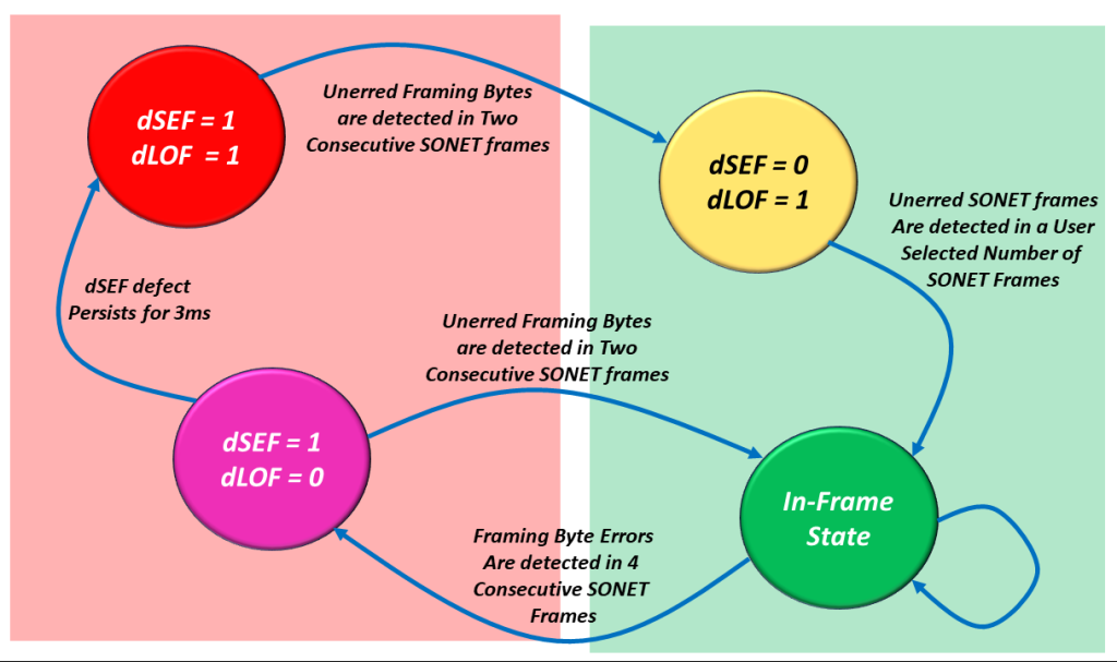
Figure 10, Illustration of the SEF/LOF Declaration/Clearance Machine Diagram – In which states will the Receive STS-1 Frramer declare or clear the dLOF defect condition.
The two states immersed in the Green Shade are those states in which the Receive STS-1 Framer will clear the dLOF defect condition.
On the other hand, the states immersed in the Red Shade are those states in which the Receive STS-1 Framer will declare the dLOF defect condition.
This concludes our introduction to the SEF/LOF Declaration/Clearance State Machine.

