This blog post presents a training video on the OPU (or Optical Payload Unit) frames. This post also contains a written overview of OPU frames as well.
OTN Lesson 2 – OPU (Optical Payload Unit) Framing
An OPU (Optical Payload Unit) frame is that portion of an OTU (Optical Transport Unit) frame that carries and transports client data throughout the Optical Transport Network (OTN).
You can Check Out the Training Video on OPU Framing Below.
The OPU frame is a subset of an ODU (Optical Data Unit) and an OTU (Optical Transport Unit) frame.
Where is the OPU Layer within the OTN Protocol Stack?
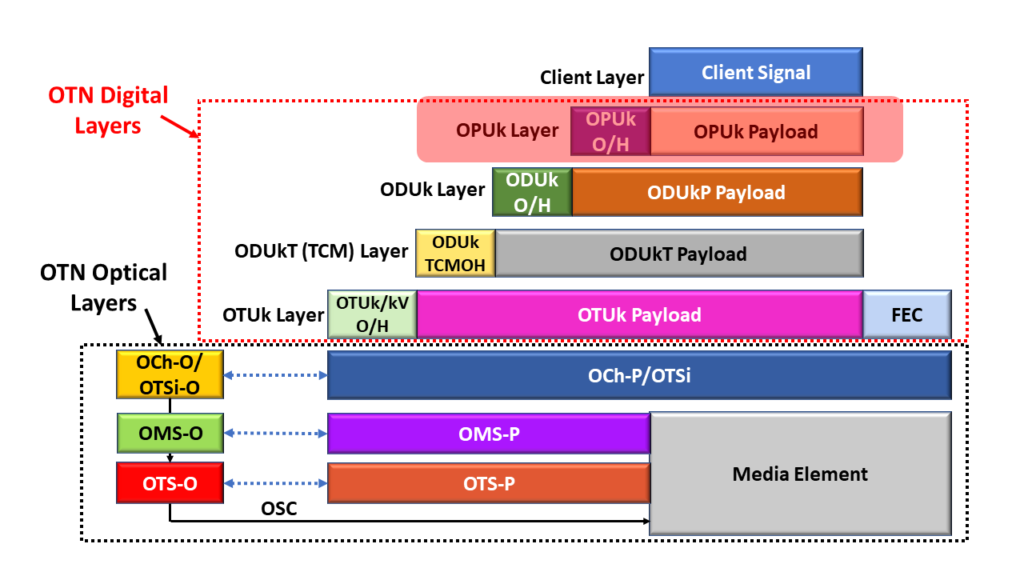
Figure 1 presents an illustration of the OTN Protocol Stack, with the OPU Layer Highlighted.
Figure 1, Illustration of the OTN Protocol Stack, with the OPU Layer Highlighted
This figure shows that the OPU Layer is the closest layer to the Client Layer. We map the client data into OPU frames and transport them throughout the OTN.
The Basic Structure of the OPU Frame
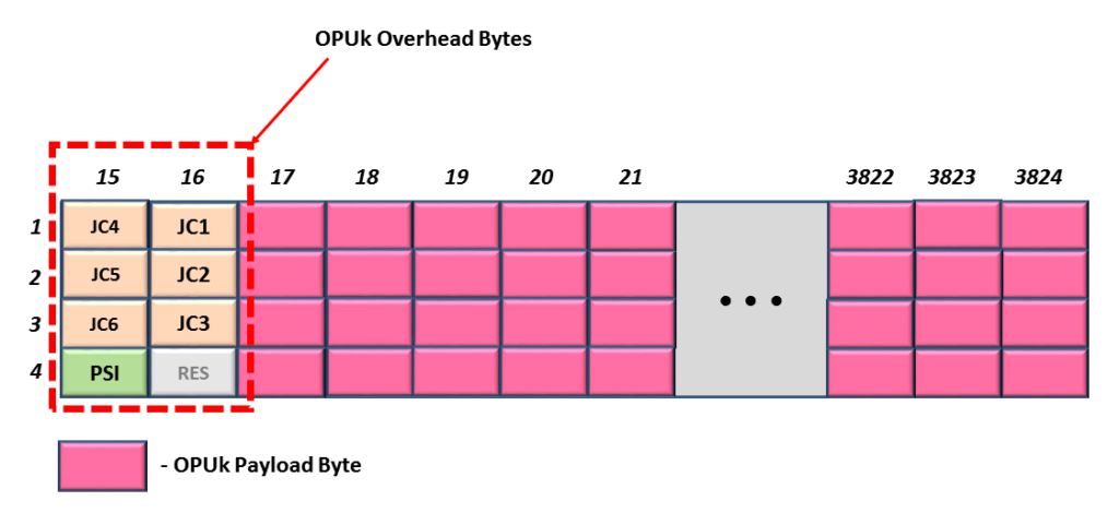
I present an illustration of the Basic (or Generic) Structure of the OPU Frame below in Figure 2.
Figure 2, Illustration of the Basic (or Generic) Structure of an OPU Frame
Each OPU frame is a 4 Row x 3810 byte-column structure. The OPU Frame consists of two basic types of fields.
The Payload Fields (which are the Pink-colored fields in Figure 2), and
The Overhead Fields (those non-Pink-colored fields on the left-hand side of the figure).
Each OPU frame contains 8 overhead bytes. And all OPU rates (except for the OPU4 frame) include 15,232 payload bytes. OPU4 frames have 15,200 payload bytes, as I show later in this post.
We use the Payload Fields to transport the client data and the Overhead fields for management purposes.
What Do the OPU Overhead Fields Manage?
In general, the OPU Overhead Fields (that I show in Figure 2) manage the following tasks.
They manage the mapping of client data into the OPU payload, and
These fields also (in turn) manage the de-mapping of client data from the OPU payload.
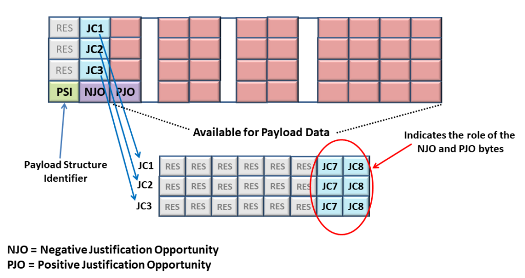
The JC1 – JC6, NJO, and PJO bytes support this effort.
They identify (to the OTN) the type of client signal that we are transporting via this particular OPUk signal.
The PSI byte supports this role.
And finally, they support mapping Lower-Speed ODUj Tributary signals into an OPU4 frame (in particular).
The OMFI byte supports this role.
What are some of the Various Types of OPU Frames
Throughout this training, we will be working with the following four types of OPU frames.
The BMP (Bit Synchronous Mapping Procedure) frame.
The AMP (Asynchronous Mapping Procedure) Applications
The GMP (Generic Mapping Procedure) Applications – up to OPU3 Rates
The GMP (Generic Mapping Procedure) Applications – for the OPU4 Rate
Let’s Discuss Each of these Types of OPU Frames below.
OPU Frames for BMP Applications
Figure 3 presents an illustration of an OPU Frame that supports BMP Mapping.
Figure 3, Illustration of an OPU Frame – supporting BMP Mapping
This is by far the simplest OPU frame.
In this particular OPU frame, the JC1 through JC3 and the NJO bytes serve no real purpose other than to occupy space. Additionally, the PJO byte will always transport client data for BMP Mapping applications.
The PSI (Payload Structure Identifier) byte will repeatedly transmit the PSI Message. We will discuss the PSI Message later in this blog post.
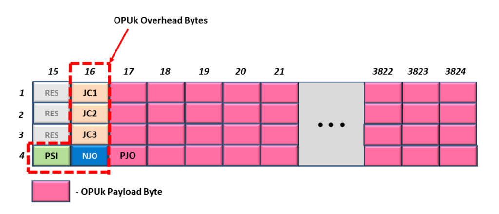
Figure 4 illustrates an OPU frame that supports AMP Mapping Applications.
Figure 4, Illustration of an OPU Frame – supporting AMP Mapping Applications
The OPU Frame in Figure 4 looks (and is) very similar to that for Figure 3. However, in the case of Figure 4, the JC1 through JC3, NJO, and PJO bytes are all active and play a significant role in AMP Mapping (or De-Mapping).
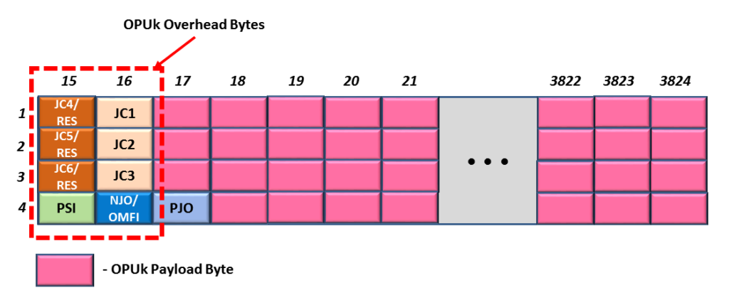
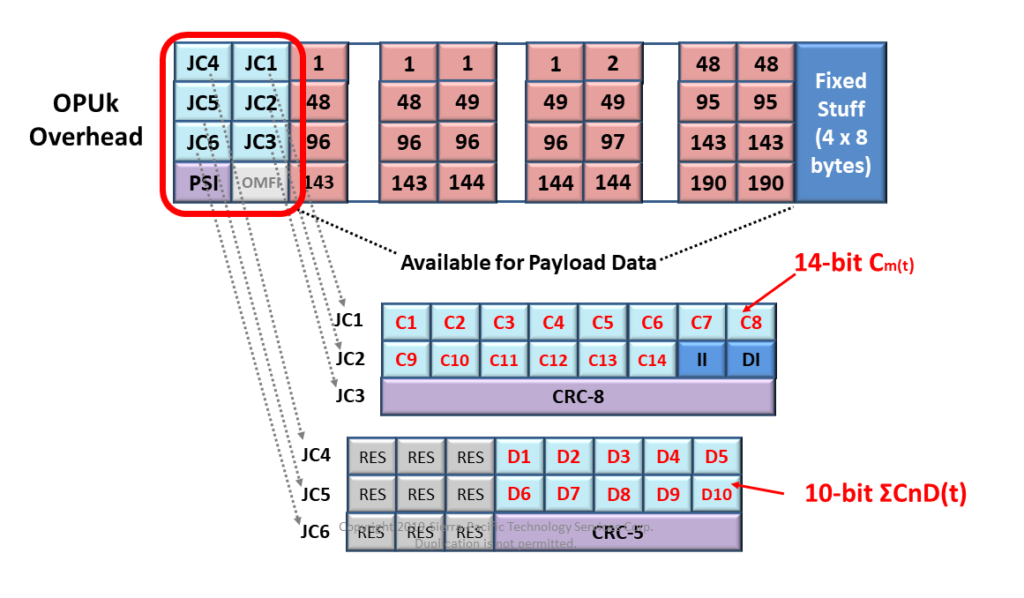
Figure 5 presents an illustration of an OPU Frame that supports GMP Mapping. In this frame, we are looking at a figure that supports OPU rates from OPU0 up to OPU3.
Figure 5, Illustration of an OPU Frame – supporting GMP Mapping Applications (OPU0, OPU1, OPU2, OPU3, and OPUflex).
As you can see, the OPU Overhead for this frame looks VERY different from that of Figures 3 and 4. AMP and BMP Mapping are closely related to each other. However, GMP is a VERY different mapping procedure from AMP or BMP.
Hence, GMP Mapping will require using 6 Justification Control fields (JC1 through JC6). Additionally, GMP does not use the NJO or PJO fields.
Finally, this brings us to the next (and final) type of OPU Frame.
OPU Frames for GMP Applications – OPU4 Applications
Figure 6 presents an illustration of an OPU Frame that also supports GMP Mapping applications. However, this particular figure is only applicable to the OPU4 Rate.
Figure 6, Illustration of an OPU Frame – supporting GMP Mapping Applications (OPU4 ONLY)
The OPU Frame in Figure 6 looks very similar to that in Figure 5, with just two differences.
The OPU4 Frame has an OFMI byte-field in the OPU Overhead in Row 4, and
The OPU4 Frame has a total of 32-byte area reserved for Fixed Stuffing.
Both OPU Frames in Figures 5 and 6 have six (6) sets of Justification Control Bytes (JC1 through JC6). These Justification Control fields are required to support GMP Mapping.
How is the OPU4 Frame different from the other OPU Frames?
Each OPU frame I show in Figures 3, 4, and 5 has 15,232 bytes within their OPU Payload.
However, because the OPU4 frame has this 32-byte Fixed Stuff area (at the back-end of this frame), it only has 15,200 bytes within its OPU Payload.
I show a different illustration of the OPU4 frame, in which the OMFI is more visible, below in Figure 7.
The OMFI (Optical Multi-Frame Identifier) byte field only exists in OPU4 Frames. Additionally, we only use the OMFI field when supporting Multiplexed Applications. We will never use the OMFI field if we are just (for example) mapping a 100GBASE-R client signal into an OPU4 payload.
For example, we will use the OMFI field if we are mapping 80 ODU0 signals into an OPU4/ODU4 server signal.
Click HERE to learn more about Multiplexed Applications (e.g., Mapping Lower-Speed ODUj Tributary Signals into a Higher-Speed ODUk Server signal) in Lesson 5.
The PSI Byte and the Payload Structure Identifier Message
Let’s talk about the PSI Byte-field.
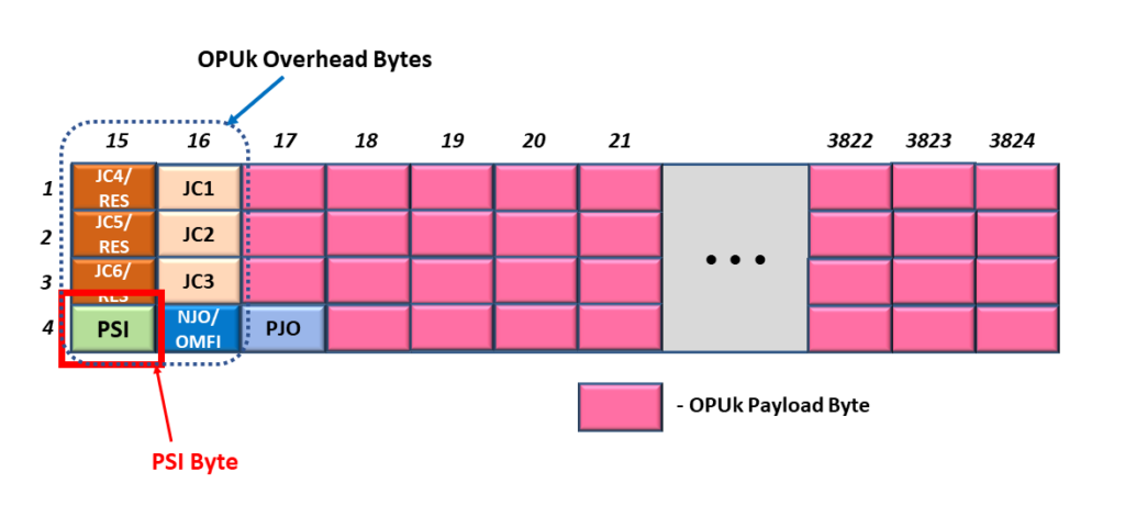
In Figure 8, I illustrate our Generic OPU Frame with the PSI Byte-field Highlighted.
Figure 8, Illustration of the Generic OPU Frame, with the PSI Byte-field Highlighted.
This figure shows that the PSI byte is located in Row 4, Byte-Column 15, within the OPU frame.
The purpose of the PSI byte is to transport the PSI Message repeatedly.
What is the PSI Message?
The PSI (or Payload Structure Identifier) Message is a 256-byte message that identifies the kind of traffic we are transporting via this particular OPU data stream.
ITU-T G.709 defines two different types of PSI Messages.
The Non-OTN Client/Non-Multiplexed Structure PSI Message and
The Multiplexed Structure – PSI Message
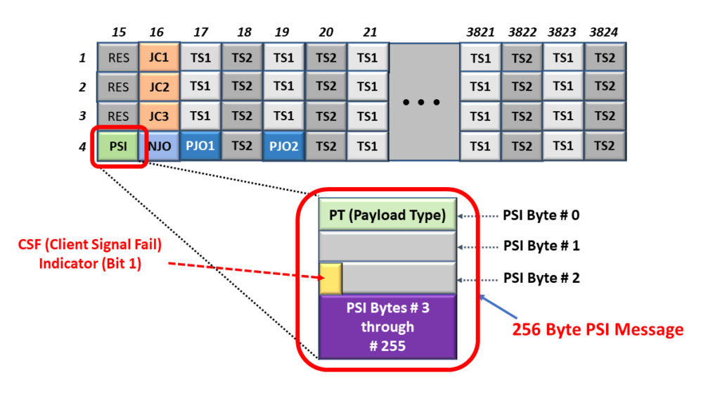
Figure 9 presents an illustration of an OPU Frame, with the PSI Byte Highlighted, along with a breakout of the Non-OTN Client/Non-Multiplexed Structure PSI Message.
Figure 9, Illustration of the OPU Frame, with the PSI Byte-field highlighted and a breakout of the Non-OTN Client/Non-Multiplexed Structure PSI Message.
Likewise, Figure 10 presents an illustration of an OPU Frame, with the PSI Byte Highlighted, along with a breakout of the Multiplexed Structure PSI Message.
Figure 10, Illustration of the OPU Frame, with the PSI Byte-field highlighted and a breakout of the Multiplexed Structure PSI Message.
What is the Non-OTN Client/Non-Multiplexed Structure PSI Message?
The Non-OTN Client/Non-Multiplexed Structure PSI Message is one variation of a PSI Message. This message is 256 bytes in length (just like its Multiplexed Structure counterpart).
We use this type of PSI Message when working with an OPU frame that is transporting a Single Non-OTN Client Signal (such as 1000BASE-X or 100GBASE-R).
The easiest way to tell if you are working with the Non-OTN Client/Non-Multiplexed PSI Message is if you see the CSF (Client Signal Fail) Bit-field within PSI byte 2.
What is the Multiplexed Structure PSI Message?
The Multiplexed Structure PSI Message is the other variant of a PSI Message.
We use this type of PSI Message when working with an OPU Frame transporting numerous Lower-Speed ODUj Tributary Signals.
The easiest way to tell if you are working with the Multiplexed Structure PSI Message is to see if you do NOT see the CSF (Client Signal Fail) Bit-field within PSI Byte 2.
How Do We Transport the PSI Message?
Since an OPU frame only contains a single PSI Byte, each PSI Message (whether it is the Non-OTN Client/Non-Multiplexed or the Multiplexed-Structure type) is 256 bytes; we have to transport each PSI Message over a stream of 256 consecutive OPU frames.
The Source PTE will continuously transmit the relevant PSI Message over and over.
Again, this PSI Message aims to inform the OTN of the type of client data we are transporting within this particular OPU data stream.
What is the PT (or Payload Type) Byte?
If you take a close look at the PSI Messages within both figures 9 and 10, then you notice that the very first byte within each of these PSI Messages is the PT (or the Payload Type) byte.
The Payload Type byte is key to helping us identify the type of traffic that we are transporting via this OPU data stream.
Table 1 lists the many standard values for PT and the corresponding traffic we are transporting within our OPU data stream.
Table 1, Listing of the Many ITU-T G.709 Standard Values of PT (Payload Type) and the Corresponding Client Signal(s) we are transporting within our OPU data stream.
Payload Type Value (Hex)
Interpretation (Client Data Type)
01
Experimental Mapping (Note 3)
02
Asynchronous CBR Mapping, see Clause 17.2
03
Bit-Synchronous CBR Mapping, See Clause 17.2
04
Not Available (Note 2)
05
GFP Mapping, See clause 17.4
06
Not Available (Note 2)
07
PCS Codeword Transparent Ethernet Mapping:
1000BASE-X into OPU0, see Clause 17.7.1 and 17.7.1.1
40GBASE-R into OPU3, see Clauses 17.7.4 and 17.7.4.1
100GBASE-R into OPU4, see Clauses 17.7.5 and 17.7.5.1
08
FC-1200 into OPU2e mapping, see Clause 17.8.2
09
GFP Mapping into Extended OPU2 Payload, see Clause 17.4.1 (Note 5)
0A
STM-1 Mapping into OPU0, see Clause 17.7.1
0B
STM-4 Mapping into OPU0, see Clause 17.7.1
0C
FC-100 Mapping into OPU0, see Clause 17.7.1
0D
FC-200 Mapping into OPU1, see Clause 17.7.2
0E
FC-400 Mapping into OPUflex, see Clause 17.9
0F
FC-800 Mapping into OPUflex, see Clause 17.9
10
Bit stream with Octet timing mapping, see Clause 17.6.1
11
Bit stream without octet timing mapping, see Clause 17.6.2
12
IB SDR mapping into OPUflex, see clause 17.9
13
IB DDR mapping into OPUflex, see clause 17.9
14
IB QDR mapping into OPUflex, see Clause 17.9
15
SDI mapping into OPU0, see Clause 17.7.1
16
(I.485/1.001) Gbit/s SDI mapping into OPU1, see Clause 17.7.2
17
1.485 Gbit/s SDK mapping into OPU1, see Clause 17.7.2
18
(2.970/1.001) Gbit/s SDI mapping into OPUflex, see clause 17.9
19
2.970 Gbit/s SDI mapping into OPUflex, see Clause 17.9
1A
SBCON/ESCON mapping into OPU0, see clause 17.7.1
1B
DVB_ASI mapping into OPU0, see clause 17.7.1
1C
FC-1600 mapping into OPUflex, see Clause 17.9
1D
FlexE Client mapping into OPUflex, see Clause 17.11
1E
FlexE aware (partial rate) mapping into OPUflex, see Clause 17.12
ODU Multiplex Structure supporting ODTUk.ts or ODTUk.ts and ODTUjk, see Clause (GMP capable) (Note 6)
22
ODU Multiplex Structure supporting ODTUCn.ts, see Clause 20 (GMP capable)
30
25GBASE-R mapping into OPUflex, see Clause 17.13
31
200GBASE-R mapping into OPUflex, see Clause 17.13
32
400GBASE-R Mapping into OPUflex, see Clause 17.13
55
Not Available (Note 2)
66
Not Available (Note 2)
80 - 80F
Reserved Codes for Proprietary Use (Note 4)
FD
NULL Test Signal Mapping, see Clause 17.5.1
FE
PRBS Test Signal Mapping, see Clause 17.5.2
FF
Not Available (Note 2)
NOTES from Table 1
There are 198 spare codes left for future international standardization. Refer to Annex A of ITU-T G.806 for the procedure to obtain one of these codes for a new Payload Type.
These values are excluded from the set of available code points. These bit patterns are present in ODUk maintenance signals or were used to represent client types that are no longer supported.
The value “01” is only used for experimental activities in cases where a mapping code is not defined in this table. Refer to Annex A of ITU-T G.806 for more information on the use of this code.
These 16 code values will not be subject to further standardization. Refer to Annex A of ITU-T G.806 for more information on the use of these codes.
Supplement 43 (2008) to the ITU-T G-series of Recommendations indicated that this mapping was recommended using PT = 0x87.
Equipment supporting ODTUk.ts for OPU2 or OPU3 must be backward compatible with equipment that supports only the ODTUjk. ODTUk.ts capable equipment transmitting PT = 0x21 which receive PT = 0x20 from the far-end shall revert to PT = 0x20 and operate in ODTUjk only mode. Refer to ITU-T G.798 for the specification.
As you can see from Table 1, if we receive an OPU4 signal in which the Payload Type (PT) = 0x07, then this means that this OPU4 signal is transporting a 100GBASE-R client signal. This is one example of how the PSI Message (which contains the PT byte) will inform us of the type of client signal(s) that are transporting via this OPU signal.
We will discuss OPU traffic, in which PT = 0x20 and 0x21 extensively in Lesson 5.
What is the CSF (Client Signal Fail) Bit-field?
As client circuitry (such as an Ethernet MAC) maps its traffic into an OTN signal (such as an OPU4 data-stream), it is expected to monitor the quality of the client signal it provides to the OPU Mapper.
If this client circuitry determines that there is a problem with the data (that it is providing to the OPU Mapper), then it is expected to assert the CSF (Client Signal Fail) bit-field.
The CSF bit-field will travel throughout the OTN (via the PSI Message, within the OPU data stream). This bit-field aims to alert the client circuitry (at the remote PTE) that the underlying client signal is corrupted or defective. In other words, CSF is a caution signal.
It’s like the Biohazard Sign I show in the Figure below.
Figure 11, A Warning Sign – Similar (in the role) to the CSF (Client Signal Fail) Bit-field.
You Can Also Check Out the OPU Training Video Below.
This post presents both the Training Video and Introductory Material for using the Generic Mapping Procedure (GMP) to map Non-OTN client data into an OPU data-stream.
OTN Lesson 4 – Mapping a Non-OTN Client Signal into an OPU Frame using the Generic Mapping Procedure (GMP)
This post includes a video that describes the GMP (Generic Mapping) Procedure – for mapping a Non-OTN client signal into an OTN signal (OPU frame).
This video also describes how we use the various JC (Justification Control) fields within the OPU overhead to manage the mapping of Non-OTN client data into an OPU frame.
Additionally, this video describes how we use these overhead fields to manage the de-mapping of this Non-OTN client data from an OPU frame.
NOTE: The roles of the JC fields are very different for GMP than for AMP and BMP.
This post introduces Video Training for using AMP and BMP to mapping Non-OTN Client Signals into an OPU Data-Stream.
OTN Lesson 4 – Mapping Non-OTN Client Signals into an OPU Frame, using BMP or AMP
This blog post presents a video discussing the BMP (Bit-Synchronous Mapping) and AMP (Asynchronous Mapping) Procedures in detail.
This video describes the conditions and circumstances in which you would choose one mapping procedure over another.
This video also describes how we use some of the OPU overhead fields to manage the mapping of Non-OTN payload data into an OPU frame and how we use these overhead fields to control the de-mapping of that same Non-OTN payload from an OPU frame.
This blog post briefly describes the term pF_EBC (Far-End Errored Block Error).
What is the pF_EBC (Far-End Errored Block Count) Performance Monitoring Parameter for the OTUk Layer?
The purpose of this blog post is to briefly define and describe the pF_EBC (Far-End Errored Block Count) Performance Monitoring parameter that the OTN (Sink) STE (or OTUk_TT_Sk Atomic Function) will compute and tally.
The Sink STE (or OTUk_TT_Sk function) will include information on the pF_EBC parameter within each Performance Monitoring report it sends to System Management.
NOTES:
The OTN PTE (ODUP_TT_Sk Atomic Function) also monitors and generates information on the pF_EBC (Far-End Errored Block Count) parameter at the ODUk Layer. Please see the pF_EBC at ODUk Layer Post for more details on this parameter.
Throughout this post, I will use the terms: OTN STE and OTUk_TT_Sk Function interchangeably. In the context of this blog post, these two terms mean the same thing.
Introduction
At the OTUk Layer, the OTN (Sink) STE is the entity that is responsible for detecting and reporting Far-End Errored Block Counts (or SM-BEI errors).
As the Sink STE receives and monitors its incoming OTUk signal, it will check for many things. It will continuously scan the incoming OTUk signal for bit (or symbol) errors (e.g., SM-BIP-8, FEC, etc.). It will also check for Service-Affecting defects (e.g., dTIM, dLOM, dLOF, dAIS, dLOS-P, etc.).
New Comprehensive OTN Training…Available Now. Click on the Banner Below to Learn More!!!
Discounts Available for a Short Time!!!
Definition of Terms:
Before we proceed, we need to define the following terms for this blog post:
Block: In this case, we define a block as an OTUk frame.
Far-End Errored Block: In this blog post, we define a far-end errored block as any OTUk frame that contains a value for the SM-BEI count that ranges anywhere between 1 and 8. Anytime the OTN STE receives a block with an SM-BEI count value of 0x0, we consider that block to be un-erred.
As the Sink STE checks the incoming OTUk signal for errors and defects, it will also record the total number of far-end errored blocks it detects for each one-second period.
At the end of a given one-second period, the Sink STE will load the total number of far-end errored block counts (detected in the most recent one-second period) into the variable pF_EBC.
The Sink STE will then report this value for pF_EBC to System Management as a part of its Performance Monitoring report.
Table 1 presents the number of blocks/second that each type of OTUk signal will transport for each value of k.
Table 1, Number of Blocks/Second for each OTUk Rate.
OTUk Type
Number of Blocks/Second
OTU1
20,421
OTU2
82,026
OTU3
329,492
OTU4
856,388
OTUCn
n x 860,177
So How does the OTN STE tally Errored Blocks for the pF_EBC parameter?
As the Sink STE receives and monitors its OTUk signal, it will continually check the SM-BEI counts within each incoming OTUk frame (or block).
Anytime the Sink STE receives an OTUk frame in which the SM-BEI value is anywhere from 1 to 8, it will increment its internal (pF_EBC Counter) by 1.
NOTE: This means that even if the Sink STE receives an SM-BEI value of “8”, it will still just increment its pF_EBC Counter by 1 (not 8).
Conversely, the Sink STE will not increment its internal pF_EBC Counter whenever it receives an OTUk frame (or block) that contains an SM-BEI value of 0, or 9 through 15. The Sink STE consider these type of OTUk frames to be un-erred.
At the end of each one-second period, the Sink STE will load the contents of this internal counter into the pF_EBC parameter. The Sink STE will then include that information within its Performance Monitor report that it sends to System Management.
Are there any Times or Conditions during which the Sink STE will NOT tally Errored Block Counts for the pF_EBC parameter?
ITU-T G.798 states that the OTUk_TT_Sk function will stop tallying Errored Blocks for the pF_EBC parameter whenever the upstream circuitry (e.g., the OTSi/OTUk_A_Sk or OTSiG/OTUk_A_Sk Atomic Function) asserts the CI_SSF input of the OTUk_TT_Sk function.
In other words, the Sink STE will not tally any Errored Block Counts (for the pF_EBC parameter) whenever it (e.g., the OTSi/OTUk_A_Sk or OTSiG/OTUk_A_Sk functions) declare any of the following service-affecting defect conditions.
Is there such a thing as Near-End Errored Block Counts?
Throughout this post, we have used the term Far-End Errored Block Count. Does this mean that there is another parameter called Near-End Errored Block Count?
This post briefly defines the SM-BEI (Section Monitoring – Backward Error Indicator) parameter. It also describes how an OTN Network will transmit the SM-BEI parameter from one Network Element to another.
What is the OTUk-BEI (Backward Error Indicator) or SM-BEI Parameter?
The purpose of this post is to define the SM-BEI (Section Monitor – Backward Error Indicator) parameter that a Source STE will generate, and a Sink STE will tally at the OTUk-Layer.
Introduction
In another post, we describe how the Sink STE (OTUk_TT_Sk function) will compute and verify the SM-BIP-8 value within each incoming OTUk frame.
NOTE: I will use the terms Sink STE and OTUk_TT_Sk function interchangeably throughout this post.
The Sink STE performs this task to check for any occurrences of bit errors during data transmission (over optical fiber) from the STE Source Terminal to the STE Sink Terminal.
However, just as the Sink STE (through its near-end Source STE) sends the SM-BDI indicator back out to the remote Terminal whenever it declares a service-affecting defect. The Sink STE (again, through its near-end Source STE) will also send out information to the remote Terminal to reflect the number of BIP-8 errors detected within each incoming OTUk frame.
We call this information the Backward-Error Indicator (or BEI). I will explain how we generate and transport this parameter below.
A High-Level Overview of the SM-BEI Parameter and How we Use it.
Before we get into the details of how things work with the various Atomic Functions and Ports, let’s spend some time discussing the underlying philosophy for transmitting the SM-BEI indicator.
Let us consider two Network Elements. We will call one Network Element, N.E East, and the other Network Element N.E. West. We have connected these two networks via a Bidirectional Optical Connection, as shown below in Figure 1.
Figure 1, Illustration of Network Elements East and West connected over a Bidirectional Fiber Optic Connection.
Now let’s consider two possible cases when dealing with SM-BIP-8 errors and SM-BEI.
The Unerred Case (where the Number of BIP-8 Errors = 0) and
The Erred Case (where the Number of BIP-8 Errors = 5)
The Unerred Case (where the Number of BIP-8 Errors = 0)
Let’s assume that the OTUk Transceiver and OTUk Framer (within Network Element EAST) are not detecting any BIP-8 errors within a given OTUk frame.
We show this case below in Figure 2.
Figure 2, Illustration of Network Element EAST detecting NO BIP-8 Errors within OTUk frame # n
Please note that in Figure 2, I show that both the OTUk Transceiver and OTUk Framer blocks (within Network Element EAST)are detecting ZERO BIP-8 errors. I show this because many OTUk Transceivers will also include some OTUk Framing capability and can detect and flag BIP-8 errors.
In this case, Network Element EAST will respond to this ZERO BIP-8 Error condition by setting the BEI field (within its next outbound OTUk frame – back to Network Element WEST) to “0x00”.
Why “0000”?
Because that’s the Number of BIP-8 Errors that the OTUk Transceivers/Framer blocks have detected in their most recently received OTU frames.
Figure 3 shows Network Element EAST setting the BEI field to 0x00 within its next outbound OTUk frame.
Figure 3, Illustration of Network Element EAST responding to the NO BIP-8 Error Condition by setting BEI = 0 within its next outbound OTUk frame.
Both the OTUk Transceiver and Framer (within Network Element WEST) will receive this OTUk frame (with BEI = 0), and it will “know” the quality of its OTUk signal (out to Network Element EAST) is GOOD.
Therefore, the BEI field (within the OTUk Overhead) gives a Network Element a way to provide feedback to an upstream Network Element about the quality of its output signal.
As long as Network Element WEST receives OTUk frames with the BEI field set to 0, it has some indication that it is transmitting a good quality OTUk signal out to Network Element EAST.
NOTE: Since this is a bidirectional connection between Network Elements EAST and WEST, then Network Element WEST can (and will) provide the same type of feedback to Network Element EAST.
Now let’s move on to the Erred Case.
The Erred Case (where the Number of BIP-8 Errors = 5)
Now that we have covered the No-Error condition let’s cover a different situation. Let us assume that Network Element EAST has just received an OTUk frame, which detects 5 BIP-8 errors.
I show an illustration of this condition below in Figure 4.
Figure 4, Illustration of Network Element EAST detecting 5 BIP-8 Errors within OTUk Frame # n
In this case, Network Element EAST will respond to this error condition by setting the BEI field (within its very next outbound OTUk frame – back out to Network Element WEST) to “0x05” (e.g., the same number of BIP-8 errors that it detected) within its recently received OTUk frame.
Why “0x05”?
Because that’s the number of BIP-8 bit errors that Network Element EAST has detected within its most recently received OTUk frame.
Figure 5 shows Network Element EAST setting the BEI field to 0x05 within its next OTUk frame.
Figure 5, Illustration of Network Element EAST responding to the 5 BIP-8 Error Condition by setting BEI = 5 within its next outbound OTUk frame
In this case, since Network Element EAST sets the BEI-field to “0x05”, it is giving Network Element WEST some feedback that it (Network Element EAST) is having problems with the OTUk data-stream that it is receiving from Network Element WEST.
Now that we understand the underlying philosophy behind using the SM-BEI fields, let’s discuss the SM-BEI parameter in greater detail.
New Comprehensive OTN Training…Available Now. Click on the Banner Below to Learn More!!
Discounts Available for a Short Time!!!
An In-depth Discussion – How Does the Sink STE generate the BEI Parameter?
In the SM-BIP-8 Post, I mentioned that the Sink STE would locally compute its version of the SM-BIP-8 value based upon the contents within the OPUk portion of the OTUk frame that it has received.
I also mentioned that this SM-BIP-8 value is an 8-bit value.
The Sink STE (or OTUk_TT_Sk function) will then read out the contents of the SM-BIP-8 byte two OTUk frame periods later, and it will compare these two BIP-8 values.
I show the location of the BIP-8 Value, with respect to the OTUk Frame (that we used to compute this value), below in Figure 6.
Figure 6, The Location of the BIP-8 Value, with respect to the OTUk Frame (that we used to compute this value)
Comparing the Locally Computed BIP-8 Value with the Remotely Computed Value
At this point, the Sink PTE will compare its locally-computed SM-BIP-8 value with the remotely-computed SM-BIP-8 value (read out from the SM-BIP-8 byte field – two OTUk frame periods later).
If these byte values (of BIP-8 values) are equal, then we can state that this OTUk frame incurred no bit errors during transmission over the optical fiber.
On the other hand, if these two BIP-8 values are NOT the same, then the Sink STE (or OTUk_TT_Sk function) notes how many bits (between these two BIP-8 values) must be different from each other.
In other words, as the OTUk_TT_Sk function compares its locally computed BIP-8 value and that which it reads in from the BIP-8 byte-field within the incoming OTUk data stream. It will do this by performing a bit-by-bit XOR operation with each of these byte values.
The OTUk_TT_Sk function must then count the numbers of “1s” that occur during this bitwise XOR comparison. The OTUk_TT_Sk function will come up with any of the following nine (9) possible results.
0 bits in Error – Error-Free Transmission
1 bit in Error
2 bits in Error
3 bits in Error
4 bits in Error
5 bits in Error
6 bits in Error
7 bits in Error
8 (all) bits in Error
In Figure 7, I show a draw of a Bit-Wise XOR Comparator that the OTUk_TT_Sk function can use to compare its locally-computed BIP-8 value with the remotely-computed BIP-8 value.
Figure 7, Illustration of a Bit-Wise XOR Comparator that the OTUk_TT_Sk function can use to compare its Locally-Computed BIP-8 Value with the Extracted (Remotely Computed) BIP-8 Value for a given OTUk frame
The OTUk_TT_Sk function will need to send these BIP-8 comparison results back out to the remote terminal (the source of the OTUk signal that we are monitoring) in the form of BEI (Backward-Error-Indicator) value.
How does the OTUk_TT_Sk send out SM-BEI Information to the Remote Terminal?
Once the OTUk_TT_Sk function has performed the comparison (between its locally computed BIP-8 value with the remote-computed value), it then needs to report this information back to the remote terminal.
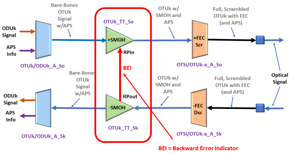
The OTUk_TT_Sk function will send a command to its collocated OTUk_TT_So function via the BEI (or RI_BEI) port.
I show a drawing of the OTUk_TT_Sk function, its collocated OTUk_TT_So function, and the BEI port below in Figure 8.
Figure 8, Illustration of the OTUk_TT_Sk, its collocated OTUk_TT_So function, and the BEI port.
The OTUk_TT_Sk function will use the BEI port to tell the OTUk_TT_So function what value it should set the BEI/BIAE nibble field to during its next outbound OTUk frame.
How does the OTUk Network Element transmit the SM-BEI Indicator?
The Network Element will transmit the SM-BEI indicator by setting the BEI/BIAE nibble-field within the SM (Section Monitoring) byte, to the BEI value, within each outbound OTUk frame.
The SM byte resides within the 3-byte SM (Section Monitoring) field of the OTUk Overhead.
Figures 9a, 9b, and 9c present the BEI/BIAE nibble-field location within an OTUk frame. First, Figure 9a shows the location of the SM field within the OTUk Overhead.
Figure 9a, The SM Field within the OTUk Overhead
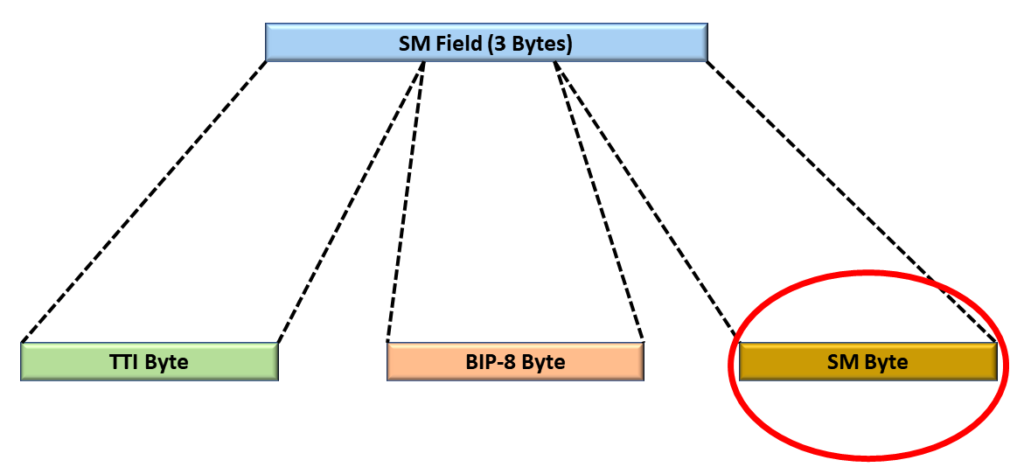
Second, Figure 9b shows the location of the SM byte within the 3-byte SM Field.
Figure 9b, The Location of the SM-Byte within the SM Field
Finally, Figure 9c presents the BEI/BIAE nibble-field location within the SM-byte.
Figure 9c, The Location of the BEI/BIAE nibble-field within the SM Byte, within the SM Field, of the OTUk Overhead.
What is the Official Interpretation of the SM-BEI/BIAE Nibble within the OTUk Frame?
The SM-BEI/BIAE Nibble does not just carry Backward Error Indication information. It also transports the BIAE (Backward Input Alignment Error Indicator).
Table 1 presents a list that defines how we should interpret each value for the SM-BEI/BIAE Nibble.
SM-BEI/BIAE[1:4] Nibble Value
Is OTUk_TT_Sk Declaring dIAE?
BEI Count (Value) if any
0000
NO
0
0001
NO
1
0010
NO
2
0011
NO
3
0100
NO
4
0101
NO
5
0110
NO
6
0111
NO
7
1000
NO
8
1001, 1010
NO
0
1011
YES (BIAE Indicator)
0
1100 through 1111
NO
0
This table shows that only nibble values of 0x01 through 0x08 reflect some (non-zero) Backward Error Indication count.
Summary
Each Network Element can use the BEI/BIAE Nibble-field within the SM byte to provide the remote Network Element with feedback on the number of SM-BIP-8 bit errors they are detecting.
The remote Network Element will note (and increment the pF_EBC parameter) each time it receives an OTUk frame, in which the SM-BEI/BIAE nibble-field ranges between 1 and 8.
In another post, I discuss the pF_EBC (Far-End – Error Block Count) parameter in greater detail.
Clueless about OTN? We Can Help!! Click on the Banner Below to Learn More!!
Discounts Available for a Short Time!!!
For More Information on OTN Posts in this Blog, click on the Image below.
This blog post briefly describes the Performance-Monitoring parameter or term pN_EBC (Near-End Errored Block Count) for the OTUk-Layer.
What is the pN_EBC (Near-End Errored Block Count) Performance-Monitoring Parameter for the OTUk Layer?
This blog post aims to briefly define and describe the pN_EBC (Near-End Errored Block Count) Performance Monitoring parameter that the Sink STE (or OTUk_TT_Sk Atomic Function) will compute and tally.
The Sink STE (or OTUk_TT_Sk function) will include information on the pN_EBC parameter within each Performance Monitoring report it sends to System Management.
NOTES:
The OTN PTE (or ODUP_TT_Sk Atomic Function) also monitors and generates information on the pN_EBC (Near-End Errored Block Count) parameter at the ODUk Layer. Please see the pN_EBC at ODUk Layer Post for more details on this parameter.
Throughout this post, I will use the terms: Sink STE and OTUk_TT_Sk Function interchangeably. In the context of this blog post, these two terms mean the same thing.
Introduction
At the OTUk Layer, the OTN (Sink) STE is the entity that is responsible for detecting and reporting Near-End Errored Block Counts (or SM-BIP-8 Errors).
NOTE: We refer to SM-BIP-8 errors as Near-End errors because these are errors that the Near-End Sink STE is detecting on its end. In contrast, we refer to the SM-BEI parameter as Far-End errors because that parameter reflects errors that a remote (or Far-End) Sink STE is detecting and reporting.
As the Sink STE receives and monitors its incoming OTUk signal, it will check for many things. It will continuously scan the incoming OTUk signal for bit (or symbol) errors (e.g., SM-BIP-8 errors, FEC errors, etc.) as well as Service-Affecting Defects (e.g., dTIM, dLOF, dLOM, dLOS-P, dAIS, etc.).
Definition of Terms:
Before we proceed, we need to define the following terms for this blog post:
Block: In this case, we define a block as an OTUk frame.
Errored Block: In this blog post, we define an errored block as any OTUk frame (or block) that contains at least one SM-BIP-8 error.
As the Sink STE checks the incoming OTUk signal for errors and defects, it will also keep a count of the number of errored blocks it detects for each one-second period.
At the end of a given one-second period, the Sink STE will load the total number of errored block counts (detected and tallied in the most recent one-second period) into the variable pN_EBC.
Since each type of OTUk signal (for a given value of k) transmits a different number of OTUk frames than does another OTUk signal (with a different value for k), each OTUk type will transmit a different number of blocks/second, as we show below in Table 1.
Table 1, Number of Blocks/Second for each OTUk Rate
OTUk Type
Number of Blocks/Second
OTU1
20,421
OTU2
82,026
OTU3
329,492
OTU4
856,388
OTUCn
n x 860,177
So How does the OTN STE tally Errored Blocks for the pN_EBC parameter?
As the Sink STE receives and monitors its OTUk signal, it will continually check for SM-BIP-8 errors.
Anytime the Sink STE receives an OTUk frame that contains at least one SM-BIP-8 error, then it will increment its internal (pN_EBC Counter) by 1.
Conversely, the Sink STE does not increment its internal pN_EBC Counter whenever it receives an OTUk frame that contains 0 SM-BIP-8 errors.
At the end of each one-second period, the Sink STE will load the contents of this internal counter into the pN_EBC parameter and include that information within its Performance Monitor report that it sends to System Management.
New Comprehensive OTN Training…Available Now. Click on the Banner Below to Learn More!!!
Discounts Available for a Short Time!!!
Are there any Times or Conditions during which the OTN STE will NOT tally Errored Block Counts for the pN_EBC parameter?
Yes, ITU-T G.798 states that the OTUk_TT_Sk function will stop tallying Errored Blocks for the pN_EBC parameter whenever the upstream circuitry (e.g., the OTSi/OTUk_A_Sk or OTSiG/OTUk_A_Sk Atomic function) asserts the CI_SSF input of the OTUk_TT_Sk function.
In other words, the OTN STE will not tally any Errored Block Counts (for the pN_EBC parameter) whenever it (e.g., the OTSi/OTUk_A_Sk or OTSiG/OTUk_A_Sk functions) declares any of the following service-affecting defects conditions.
Is there such a thing as Far-End Errored Block Counts?
Throughout this post, we have used the term Near-End Errored Block Count. Does this mean that there is another parameter called Far-End Errored Block Count?
This blog post briefly defines the pF_DS (Far-End Defect Second) Performance Monitoring parameter – for the OTUk Layer.
What is the pF_DS (Far-End Defect Second) Performance-Monitoring Parameter for the OTUk Layer?
This blog post aims to briefly define and describe the pF_DS (Far-End Defect Second) Performance Monitoring parameter that the OTN STE (or OTUk_TT_Sk Atomic Function) will compute and generate.
The OTN STE (or OTUk_TT_Sk function) will include information on pF_DS within each Performance Monitoring report it sends to System Management.
NOTES:
The OTN PTE (ODUP_TT_Sk Atomic Function) also monitors and generates information on the pF_DS (Far-End Defect Second) parameter at the ODUk Layer. Please see the pF_DS at ODUk Layer Post for more details on this parameter.
Throughout this post, I will be using the terms: OTN STE and OTUk_TT_Sk Function interchangeably. In the context of this blog post, these two terms mean the same thing.
Introduction
At the OTUk Layer, the OTN (Sink) STEis the entity that is responsible for detecting and reporting Far-End Defect Second events.
As the OTN STE receives and monitors its incoming OTUk signal, it will check for many things. It will continuously check the incoming OTUk signal for Service-Affecting Defects (e.g., dTIM(*), dLOF, dLOFLANE(*), dLOL(*), dLOM(*), dAIS (OTUk-AIS), dLOS-P, etc.) as well as bit (or symbol) errors (e.g., SM-BIP-8 errors, SM-BEI errors, FEC errors, etc.).
Another thing that the OTN STE will do (as it continuously monitors its incoming OTUk signal) is to divide each second of (monitoring) time into the following two categories:
Far-End Available (Working) Seconds, and
Far-End Defect Seconds
Anytime the OTN STE detects and categories a given one-second period as being a Far-End Defect Second, it will increment the pF_DS parameter and report that information to System Management.
New Comprehensive OTN Training…Available Now. Click on the Banner Below to Learn More!!
Discounts Available for a Short Time!!
So When does the OTN STE detect and flag a given One-Second Period as being a “Far-End Defect Second”?
ITU-T G.798 presents the following Performance Monitoring Equation for the OTUk_TT_Sk function.
dBDIis the current state of the OTUk-BDI or the Backward Defect Indicator Defect (at the OTUk Layer).
The OTN STE (or OTUk_TT_Sk function) will continuously evaluate the above equation as it monitors its incoming OTUk signal.
This equation states that the OTN STE will declare a given one-second period as being a Far-End Defect Second if it has declared the dBDI defect condition during any portion of that one second.
A given OTN STE will declare one second as a Far-End Defect Second if the remote OTN STE declares any of the following defect conditions:
OTUk-AIS
dTIM
dLOS-P
dLOFLANE
dLOL
dLOF
dLOM
In this case, the OTN STE will increment the pF_DS parameter for each second that it categorizes as a Far-End Defect Second.
Conversely, the OTN STE will declare one second as an Available Second if the remote OTN STE is not declaring any of the defects mentioned above. The OTN STE will NOT increment the pF_DS parameter in this case.
What Does This Mean in English?
Of course, if the OTN STE declares the dBDI defect condition, then this also means that the remote STE is declaring a service-affecting defect condition. In other words, the pF_DS parameter reflects the health of the remote (or Far-End) terminal.
If the remote terminal declares no service-affecting defects, the near-end terminal will not increment the pF_DS parameter. On the other hand, if the remote terminal declares a service-affecting defect, then the near-end terminal will increment the pF_DS parameters.
So, if the OTUk_TT_Sk function has declared the dBDI defect condition for even a fraction of a given one-second period, it will declare it as a Far-End Defect Second. It will also set the parameter pF_DS to 1 and report that information to System Management.
Conversely, suppose the OTN STE determines that the OTUk_TT_Sk function did not declare the dBDI defect condition during one second period. In that case, it will declare that one-second period as being a Far-End Available (Working) Second. In this case, the OTN STE will NOT set the parameter pF_DS to 1.
Are there any Times or Conditions during which the OTN STE should NOT tally the pF_DS Parameter?
Yes, ITU-T G.798 states that the OTUk_TT_Sk function (or System Management) should discard the previous and the current one-second period’s measurement of the pF_DS parameter whenever it declares either the dIAE (Input Alignment Error)(*) or dBIAE (Backward Input Alignment Error)(*) defect conditions.
We need to discard the previous one-second period reading to account for the propagation delay of the IAE signaling indicator coming from the remote terminal equipment.
Is there such a thing as a Near-End Defect Second?
Throughout this post, we have been using the term Far-End Defect Second. Does this mean that there is another parameter called Near-End Defect Second?
Answer: Yes, there is such a parameter. Please see the post on Near-end Defect Seconds (pN_DS) at the OTUk Layer for more details.
Clueless about OTN? We Can Help!! Click on the Banner Below to Learn More.
Discounts Available for a Short Time!!
And Finally, CLICK on the Image Below to see More OTN-Related Topics in this Blog.
This blog post briefly defines the pN_DS (Near-End Defect Second) Performance-Monitoring parameter – for the OTUk Layer.
What is the pN_DS (Near-End Defect Second) Performance-Monitoring Parameter for the OTUk Layer?
This blog post aims to briefly define and describe the pN_DS (Near-End Defect Second) Performance-Monitoring parameter that the Sink STE (or OTUk_TT_Sk Atomic Function) will report.
The Sink STE (or OTUk_TT_Sk function) will include information on pN_DS within each Performance Monitoring report it sends to System Management.
NOTES:
The OTN PTE (ODUP_TT_Sk Atomic Function) also monitors and generates information on the pN_DS (Near-End Defect Second) parameter at the ODUk Layer. Please see the pN_DS at ODUk Layer Post for more details on this parameter.
Throughout this post, I will use the terms: Sink STE and OTUk_TT_Sk Function interchangeably. In the context of this blog post, these two terms mean the same thing.
Introduction
At the OTUk Layer, the Sink STE is the entity that is responsible for detecting, flagging, and reporting Near-End Defect Second events.
As the Sink STE receives and monitors its incoming OTUk signal, it will check for many things.
It will continuously check the incoming OTUk signal for Service-Affecting Defects (e.g., dTIM, dLOF, dLOM, dLOFLANE, dLOL, dLOS-P, dAIS, etc.) as well as bit (or symbol) errors (e.g., SM-BIP-8 errors, FEC errors, etc.).
Another thing that the Sink STE will do (as it continuously monitors its incoming OTUk signal) is to divide each second of (monitoring) time into the following two categories:
Near-End Available (Working) Seconds, and
Near-End Defect Seconds
Anytime the Sink STE detects and categorizes a given one-second period as being a Near-End Defect Second. It will increment the pN_DS parameter and report that information to System Management.
So When does the OTN STE flag a given One-Second Period as being a “Near-End Defect Second”?
ITU-T G.798 presents the following Performance Monitoring Equation for the OTUk_TT_Sk function.
pN_DS <- CI_SSF or dTIM;
Where:
CI_SSF is the current state of the CI_SSF input pin to the OTUk_TT_Sk Atomic Function, and
dTIM is the current state of the Trail Trace Identifier Message (or OTUk-TIM) defect condition.
OK, What Does that Mean in Plain English?
The above equation means that the Sink STE will classify a given one-second period as being a Near-End Defect Second anytime it declares a service-affecting defect within its incoming OTUk signal during even a fraction of that one second.
Conversely, the Sink STE will classify a given one-second period as being a Near-End Available (or Working) second if it is NOT declaring a service-affecting defect within this OTUk signal during this one second.
How to Evaluate the Performance Monitoring Equation for pN_DS?
The Sink STE (or OTUk_TT_Sk function) will continuously evaluate the above-mentioned Performance Monitoring equation as it monitors its incoming OTUk signal.
Once again, this equation states that the Sink STE will declare a given one-second period as being a “Near-End Defect Second” if it determines that any of the following conditions are (or were ever) TRUE during that one second.
NOTE: The OTSi/OTUk_A_Sk and OTSiG/OTUk_A_Sk functions will assert their CI_SSF signal if these atomic functions declare any of the following defects conditions.
dLOS-P[i], where i represents any of the four electrical lanes in an OTL3.4/OTL4.4 Interface.
dLOFLANE[j], where j represents any one of 4 or 20 logical lanes in an OTL3.4/OTL4.4 Interface.
dAIS (OTUk-AIS) – for Single-Lane (OTSi/OTUk_A_Sk Function) Applications Only.
dLOL – for OTL3.4/OTL4.4 Applications ONLY.
dLOF
dLOM
Or if the OTUk_TT_Sk function declares the dTIM (OTUk-TIM) defect condition.
So, for example, if the OTUk_TT_Sk function has determined that the upstream circuitry asserted the CI_SSF input for even a fraction of a given one-second period, then it will classify that one-second period as being a Near-End Defect Second.
It will also set the parameter pN_DS to 1 and report that information to System Management.
Conversely, suppose the Sink STE determines that NONE of those conditions were true during the most recent one-second period. In that case, it will declare that one-second period as being a Near-End Available (Working) Second.
In this case, the Sink STE will not increment the pN_DS parameter.
New Comprehensive OTN Training…Available Now. Click on the Banner Below to Learn More!!!
Discounts Available for a Short Time!!!
Are there any Times or Conditions during which the OTN STE should NOT tally the pN_DS Parameter?
Yes, ITU-T G.798 states that the OTUk_TT_Sk function (or System Management) should discard the previous and the current one-second period’s measurement of pN_DS whenever it declares the dIAE (Input Alignment Error)(*) defect condition.
We need to discard the previous one-second period reading to account for the propagation delay of the IAE signaling indicator coming from the remote terminal equipment.
Is there such a thing as a Far-End Defect Second?
Throughout this post, we have been using the term Near-End Defect Second. Does this mean that there is another parameter called Far-End Defect Second?
This post briefly defines and describes Consequent Equations that ITU-T G.798 uses for OTN Applications.
What are Consequent Equations, and How Should You Interpret Them?
The purpose of this blog post is two-fold.
To describe the concept of Consequent Equations and
To discuss how we can use and interpret these Consequent Equations.
Introduction
Many ITU Standards (such as ITU-T G.798 for OTN Applications) will discuss many aspects of defects. These standards will define defects such as dAIS (Alarm Indication Signal) and dLOM (the Loss of Multi-frame).
These same standards will also define the criteria that an OTN Network Element (be it an STE or PTE) should use to declare or clear a given defect.
For example, ITU-T G.798 specifies all of the following defects that an OTN STE can declare and clear.
How should an STE/PTE Respond Whenever it Declares a Defect?
However, what else should an STE do whenever it declares (for example) the dLOF defect condition?
Does this STE have a responsibility to notify other STEs of this defect?
Similarly, what else should a PTE do whenever it declares (for example) the dTIM (ODUk-TIM) defect condition?
Again, does this PTE have a responsibility to notify other nearby PTEs of this defect?
The short answer to both of these questions is, “Yes, for those specific defects that I mentioned, they do have a responsibility to notify upstream and downstream equipment of the occurrence of those defect conditions.”
However, to confuse things, the PTE/STE must notify upstream and downstream PTE/STE whenever some defects occur, but not others.
How Do We Sort out This Confusion?
The Answer: Consequent Equations.
Let’s assume that a certain STE is declaring the dLOF Defect condition, as shown below in Figure 1.
Figure 1, Illustration of the STE (e.g., the OTSi/OTUk-a_A_Sk Atomic Function) declares the dLOF defect condition.
What happens next?
At this point, let’s write down the Consequent Equation that pertains to this STE (or the OTSi/OTUk-a_A_Sk function in this case):
AI_TSF-P is the current (logical) state of the AI_TSF-P input pin (to the OTSi/OTUk-a_A_Sk atomic function).
This consequent equation states that the STE (or OTSi/OTUk-a_A_Sk function) will assert its CI_SSF output pin anytime it declares any of the following defect conditions:
This consequent equation also states that the STE (the OTSi/OTUk-a_A_Sk function) will assert the CI_SSF output pin anytime the upstream atomic function asserts the AI_TSF input to this function.
NOTE: Please see the OTSi/OTUk_A_Sk Function Post for more information about this particular Atomic Function.
So What Does All of This Mean?
In Figure 2, I show the OTSi/OTUk_A_Sk function now asserting its CI_SSF output pin because it is currently declaring the dLOF defect condition.
Figure 2, Illustration of the OTSi/OTUk_A_Sk Atomic Function asserting its CI_SSF output because it is currently declaring the dLOF defect condition.
Please note that the CI_SSF output (from the OTSi/OTUk_A_Sk function) is connected to the CI_SSF input of the (downstream) OTUk_TT_Sk function.
OK, that’s great. The above Consequent Equation states that the STE (e.g., the OTSi/OTUk_A_Sk function will assert the CI_SSF output pin whenever it declares the dLOF defect.
How does that alert any other STE/PTE of the OTSi/OTUk_A_Sk function declaring the dLOF defect?
Answer: There is more to this, and it involves more Consequent Equations.
In Figure 3, I show the OTUk_TT_Sk and the OTUk/ODUk_A_Sk Atomic Functions.
I also show that the upstream (OTSi/OTUk_A_Sk function) circuitry is now asserting the CI_SSF input (to the OTUk_TT_Sk function) – as we described above.
Figure 3, Illustration of the OTUk_TT_Sk and OTUk/ODUk_A_Sk functions – with upstream circuitry asserting the CI_SSF input pin.
Now, the OTUk_TT_Sk Atomic Function happens to have two sets of Consequent Equations:
I will list each of these equations below.
aTSF <- CI_SSF or dAIS or (dTIM and (NOT TIMActDis))
aBDI <- CI_SSF or dAIS or dTIM
I will explain each of these equations below.
The First Consequent Equation – OTUk_TT_Sk Function
Let’s start with the first Consequent Equation for the OTUk_TT_Sk function.
aTSF <- CI_SSF or dAIS or (dTIM and (NOT TIMActDis))
Where:
aTSF is the current state of the AI_TSF output of the OTUk_TT_Sk Atomic Function.
CI_SSF is the current state of the CI_SSF input of the OTUk_TT_Sk Atomic Function.
dAIS is the current state of the dAIS defect condition, and
This Consequent Equation states that the OTUk_TT_Sk Atomic Function should assert the AI_TSF output signal anytime it declares any of the following defect conditions.
dTIM – Trail Trace Identifier Mismatch Defect
dAIS – AIS Defect
This Consequent Equation also states that the OTUk_TT_Sk function should assert the AI_TSF output whenever the upstream circuitry (e.g., the OTSi/OTUk_A_Sk function) asserts the CI_SSF input pin.
In Figure 4, I show the OTUk_TT_Sk function asserting its AI_TSF output pin because the upstream OTSi/OTUk_A_Sk function is asserting the CI_SSF input pin (to this function).
Figure 4, The OTUk_TT_Sk Atomic Function asserts the AI_TSF output pin because the upstream OTSi/OTUk_A_Sk function is asserting its CI_SSF input pin.
OK, now let’s look at the second Consequent Equation for the OTUk_TT_Sk Function.
The Second Consequent Equation – OTUk_TT_Sk Function
aBDI <- CI_SSF or dAIS or dTIM
Where:
aBDI is the state of the RI_BDI output (of the Remote Port Interface) of the OTUk_TT_Sk function.
Earlier in this post, we have defined CI_SSF, dAIS, and dTIM.
Therefore, this Consequent Equation states that the OTUk_TT_Sk function will assert the RI_BDI output pin anytime it declares the dAIS or dTIM defect conditions.
This equation also states that the OTUk_TT_Sk function will also assert the RI_BDI output pin anytime the upstream circuitry asserts the CI_SSF input (to the OTUk_TT_Sk function).
If you recall from the OTUk_TT_So and OTUk_TT_Sk posts, I state that anytime the OTUk_TT_Sk function asserts the RI_BDI output pin, it will command its collocated OTUk_TT_So function to transmit the OTUk-BDI indicator back out to the remote end.
I show this phenomenon below in Figure 5.
Figure 5, The OTUk_TT_Sk function asserts its RI_BDI output pin, commanding its Collocated OTUk_TT_So function to transmit the BDI (Backward Defect Indicator) back to the upstream STE because its CI_SSF is being driven HIGH.
Figure 5 shows that because the STE (OTSi/OTUk_A_Sk function) declared the dLOF defect, the downstream OTUk_TT_Sk function responded by commanding its collocated OTUk_TT_So function to transmit the OTUk-BDI indicator back to the upstream STE (the source of the defective OTUk signal).
However, we’re not done yet.
Since the OTUk_TT_Sk function is also asserting its AI_TSF output, it is also asserting the AI_TSF input to the (down-stream) OTUk/ODUk_A_Sk atomic function.
Has Inflation got You Down? Our Price Discounts Can Help You Fight Inflation and Help You to Become an Expert at OTN!!! Click Below to Learn More!!
Let’s move on to the OTUk/ODUk_A_Sk Atomic Function
As you can see in Figure 5, the OTUk_TT_Sk function, by asserting its AI_TSF output pin, is also asserting the AI_TSF input pin to the OTUk/ODUk_A_Sk function.
And the OTUk/ODUk_A_Sk function comes with several Consequent Equations of its own.
aSSF <- AI_TSF and (not MI_AdminState = LOCKED), and
aAIS <- AI_TSF and (not MI_AdminState = LOCKED)
Let’s take each of these equations, one at a time.
The First Consequent Equation – OTUk/ODUk_A_Sk Function
aSSF <- AI_TSF and (not MI_AdminState = LOCKED)
Where:
aSSF is the current state of the CI_SSF output pin (from the OTUk/ODUk_A_Sk function).
MI_AdminState reflects the current state of the MI_AdminState input signal (which the System Operator can set).
This Consequent Equation states that the OTUk/ODUk_A_Sk function will automatically assert its CI_SSF output signal whenever the upstream circuitry asserts its AI_TSF input, provided that the System Operator has not put the OTUk/ODUk_A_Sk function into the LOCKED state.
In Figure 6, I show the OTUk/ODUk_A_Sk function asserting its CI_SSF output pin because the upstream circuitry is asserting its AI_TSF input pin.
Figure 6, The OTUk/ODUk_A_Sk function asserts its CI_SSF output pin because the upstream circuitry (e.g., the OTUk_TT_Sk and OTSi/OTUk_A_Sk functions) is asserting its AI_TSF input pin.
I should also point out that APS (Automatic Protection Switching) systems often trigger (and start protection switching) whenever the OTUk/ODUk_A_Sk function asserts its CI_SSF output pin.
Now, let’s move on to the next Consequent Equation.
The Second Consequent Equation – OTUk/ODUk_A_Sk Function
If aAIS = TRUE, then the OTUk/ODUk_A_Sk function is overwriting its output signal with the ODUk-AIS Maintenance signal.
Conversely, if aAIS is FALSE, then the OTUk/ODUk_A_Sk function transmits an ODUk data stream, carrying regular client traffic.
Therefore, this Consequent Equation states that the OTUk/ODUk_A_Sk function will transmit the ODUk-AIS Maintenance Signal anytime the upstream circuitry pulls its AI_TSF input TRUE; provided that the System Operator has NOT put the OTUk/ODUk_A_Sk function into the LOCKED State.
In Figure 7, I illustrate the OTUk/ODUk_A_Sk function transmitting the ODUk-AIS Maintenance Signal because upstream circuitry (e.g., the OTUk_TT_Sk and OTSi/OTUk_A_Sk functions) is asserting its AI_TSF input.
Figure 7, The OTUk/ODUk_A_Sk function replaces the ODUk signal (carrying client data) with the ODUk-AIS Maintenance Signal whenever upstream circuitry asserts its AI_TSF input.
Then, we could state that if the OTN STE declares the dLOF defect (as we discussed earlier in this post), then that same OTN STE will do all of the following:
It will transmit the OTUk-BDI indicator back towards the upstream STE.
The OTN STE will also replace the missing (or defective) ODUk data stream (carrying client traffic) with the ODUk-AIS Maintenance Signal, and
It will also trigger APS (Automatic Protection Switching) activities by asserting the CI_SSF output (from the OTUk/ODUk_A_Sk function).
I show a drawing of these actions below in Figure 8.
Figure 8, Illustration of the OTN STE responding to the dLOF Defect Condition
Conclusion
Thanks to Consequent Equations, we can define and predict how an OTN STE or PTE will respond to certain defects.
I have presented Consequent Equations in each post pertaining to OTN Atomic Functions.
Clueless about OTN? We Can Help!! Click on the Banner Below to Learn More.
Discounts Available for a Short Time!!!
Click on the Image below to See More OTN- or Protection-Switching-Related Posts