What is Running Disparity (RD)?

The Running Disparity (or RD) is defined as the difference between the number of logic 1 bits and logic 0 bits between the start of a data sequence and a particular instant in time during its transmission.


What is Running Disparity (RD)?

We define the Running Disparity (or RD) as the difference between the number of logic 1 bits and logic 0 bits between the start of a data sequence and a particular instant in time during its transmission.

In other words, the RD for a character is the difference between the number of logic 1 bits and logic 0 bits in that character.

Hence, if there are more logic 1 bits than logic 0 bits (within a character or string of consecutive bits), we can state that the RD is positive.

If there are more logic 0 bits than logic 1 bits, then we can state that the RD is negative.

Finally, if the number of logic 1 and logic 0 bits are the same, we can state that the RD is neutral or zero.

We can express the Running Disparity as either an integer or as a ratio:

EXPRESSING RD AS AN INTEGER NUMBER:

If you wish to express the RD of a character or string (of consecutive bits) as an integer number, then you can calculate the RD with the following equation:

RD = (Number of Logic 1 bits in the character or string) – (Number of Logic 0 bits in the character or string)

For example:  

The running disparity of the hexadecimal expression of 0x78 is 0.

To understand why this is the case, if we were to express this value in its binary format, we get 0111 1000.  The binary expression (for this value) contains four 0s and four 1s.

Thus, RD = 4 – 4 = 0

On the other hand, the running disparity of the hexadecimal expression of 0x7F is +6.

Again, if we were to express this value in its binary format, we would get 0111 1111.  The binary expression (for this value) contains seven 1s and one 0.

Hence, RD = 7 – 1 = +6

EXPRESSING RD AS A RATIO:

If you wish to express the RD of a character or string (of consecutive bits) as a ratio, then you would do the following:

  • Count the total number of logical “1s” in the expression.
  • Count the total number of logical “0s” in the expression.

And then express this information in the following format:

Number of Logical 1s (in character/string) :  Number of Logical 0s (in character/string)

For example:

We express the running disparity of the hexadecimal expression of 0x78 as:

4:4, which we can reduce (or simplify) to 1:1.

Likewise, we can compute and express the RD for the value 0x7F as
7:1.

Some communication and data storage system standards (such as Gigabit Ethernet/1000BASE-X, Fibre-Channel, etc.) require that we maintain the RD as near to neutral as possible.

The system designer must ensure that the ratio of logical 1 bits to logical 0 bits (over time) should be kept close to 1:1.

Thus, the System Designer must follow any character/string with negative disparity with another character/string with an equal amount of positive disparity, and vice-versa.

Keeping RD to a minimum is to maintain dc balance on the transmission medium.

The System Designer must ensure that the RD does not increase without bounds.

The 8B/10B line code is a specific example of a line code that requires and exercises control over RD.

NOTE:  Controlling and monitoring RD can also help detect transmission errors.

Has Inflaton got You Down? Our Price Discounts Can Help You Fight Inflation and Help You Become an Expert on OTN!! Click on the Banner Below to Learn More!!

Discounts Available for a Short Time!!!

What does the expression 100GBASE-R Mean?

This post defines and describes the expression 100GBASE-R for 100Gbps Ethernet Applications.


What does the expression 100GBASE-R Mean?

For Ethernet applications, the IEEE 802.3 standard states that the term 100GBASE-R represents a group (or family) of Physical Layer (e.g., 100Gbps Transceiver) devices that do the following:

  • When it transmits its data towards the PMD (Physical Medium Dependent) device, it will:
    • Encode the CGMII data into the 64B/66B PCS (Physical Coding Sublayer) code.
      • This is what the -R suffix means, by the way.  
    • Divide (or de-multiplex) its outbound traffic into 20 PCS Lanes by routing each 66b (66 bit) block to a different PCS lane (in a round-robin manner).
    • It will often multiplex these 20 PCS Lanes into 4 or 10 physical (or electrical) lanes for CAUI-4 and CAUI-10 applications, as it transports this data to an Optical Transceiver (or PMD), respectively.
  • When it receives data (from the PMD), it will:
    • De-multiplexes these CAUI-4/CAUI-10 physical (or electrical) lanes of traffic that it receives from the Optical Transceiver into 20 PCS Lanes.
    • Combines (or multiplexes) these 20 PCS Lanes into a single stream of traffic as it routes this data towards the MAC (Media Access Control) device.
    • Decodes this data from the 64B/66B PCS code back into the CGMII (100Gbps Media Independent Interface) format.  

NOTE:  I discuss some of this processing (with 100GBASE-R data) for ITU-T G.709, Annex E mandated handling (before GMP Mapping this data into the OPU4 Payload) in Lesson 10; within THE BEST DARN OTN TRAINING PRESENTATION…PERIOD!!!

In Summary

In summary, these 100Gbps Ethernet devices will encode their “outgoing” data into the 64B/66B PCS code before transmitting it over some media.  

These 100Gbps Ethernet devices will also decode their “incoming” data from the 64B/66B PCS code (to restore the data to its original CGMII content) as it receives this data.

In other words, the 100Gbps Ethernet system will encode this data into the 64B/66B PCS format solely to transport this data across the communication media.  

Once this Ethernet data has arrived (at the other end of the media), the Ethernet system will decode this data (from the 64B/66B PCS format) to restore it to its original content.

The bit rate of this 64B/66B PCS encoded 100Gbps Ethernet data stream is 103.125Gbps ‡ 100pm.

Why Do We Encode our 100Gbps Ethernet Data into this 64B/66B PCS Code before we transmit this data over Optical Fiber?

We encode this 100Gbps Ethernet (CGMII) data into this 64B/66B PCS Code before we:

  • Transmit this data over Optical Fiber, or
  • Map this data into an OPU4 Frame (again for transmission over Optical Fiber).

There are several reasons we encode this data (before transmission over Optical fiber).  But the main goals are to convert this data into a more conducive format for transport over Optical Fiber.  More specifically, by converting this data into the 64B/66B code, we:

  • Minimize Running Disparity (e.g., maintain DC balance) with our data, and 
  • Ensure that we have no long strings of consecutive “1s” or consecutive “0s” within the data, we transport over Optical Fiber.  
  • Offer greater management capability (within our 100Gbps signal) by including Sync Bits within our 66-bit blocks.   These Sync bits permit us to designate certain 66-bit blocks as data blocks and other 66-bit blocks as control blocks.  I discuss some of this in detail in Lesson 10 within THE BEST DARN OTN TRAINING PRESENTATION…PERIOD!!!

Clueless about OTN? We Can Help!!! Click on the Banner Below to Learn More!!!

Discounts Available for a Short Time!!

The Various 100GBASE-R Transceiver Devices

IEEE 802.3 also states that the Physical Layer (Transceiver devices) supporting the following standards must support the 100GBASE-R PCS encoding/decoding scheme.

  • 100GBASE-CR4
  • 100GBASE-CR10
  • 100GBASE-SR4
  • 100GBASE-SR10
  • 100GBASE-KP4
  • 100GBASE-KR4
  • 100GBASE-LR4
  • 100GBASE-ER4

Please check out the post on 64B/66B encoding to learn more about that encoding scheme.

Where is this PCS Encoder/Decoder Located?

IEEE 802.3 states that the 100GBASE-R PCS block (e.g., the entity that performs the PCS Encoding/Decoding) resides between the Reconciliation Layer and the PMA (Physical Medium Attachment), as shown in Figure 1 below.

IEEE 802.3 100Gbps Ethernet Architectural Diagram

Figure 1, Architectural Positioning of 100Gigabit Ethernet (from the IEEE 802.3 Standard)

But, in a real system, this PCS Encoder/Decoder often resides in the same IC containing the MAC (Media Access Controller).  

Figure 2 illustrates a MAC that includes the PCS Encoder and Decoder functions.

100GBASE-R Encoder and Decoder in MAC IC

Figure 2, Illustration of a Connection between the MAC and a 100Gbps Transceiver IC

This figure also shows the MAC or Switch IC exchanging data with the 100Gbs Ethernet Transceiver IC over a CAUI-4 or CAUI-10 Interface.

Has Inflation got You Down? Our Price Discounts Can Help You Fight Inflation and Help You Become an Expert on OTN!! Click on the Banner Below to Learn More!!!

Temporary Discounts Available Now!!

Manchester Encoding

This post presents a description of the Manchester Line Code. It also describes the Manchester Line Code’s strength, weaknesses and where it is deployed.

What is the Manchester Line Code

The Manchester Line Code is a line code that transports both data and timing information on a single serial binary data stream.

We use the Manchester Line Code in the Physical Layer.

A Manchester Line Encoder works by encoding each data bit to be either low-then-high or high-then-low – for equal amounts of time.  

Since this encoded data is “high” and “low” for equal times, there is no DC bias within this signal.

More specifically, IEEE 802.3 specifies that a Manchester encoder should encode a “1” bit by setting the output to a logic “low” for the first half of a bit period and then by setting the output to a logic “high” for the second half of this bit period.  

This encoding scheme requires a rising clock edge at the middle of this bit period.  

Conversely, IEEE 802.3 also specifies that a Manchester encoder should encode a “0” bit by setting the output to a logic “high” during the first half of a bit period and then set the output to a logic “low” for the second half of the bit period.  

This situation requires a falling clock edge to occur in the middle of this bit period.

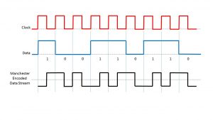
Figure 1 shows a drawing of a data stream that we have encoded into the Manchester format.  

The very top trace is the clock signal.  The middle signal trace contains the data (that we wish to encode).  Finally, the bottom signal trace presents the resulting encoded data.

Manchester Line Code

Figure 1, An Drawing of a Data Stream that we have encoded into the Manchester format

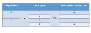
Manchester coding works by exclusive-ORing (XOR) the Original Data and the Clock signal, as Table 1 presents below.

Table 1, Encoding Data into the Manchester Line Code

Manchester Encoding Algorithm

Where did the Manchester Line Code come from?  

The University of Manchester (in the United Kingdom) developed the Manchester Line Code.

What are its strengths?  

The Manchester Line Code has two primary strengths:

  1. It is an electrically balanced line code and has no DC bias.
  2. It provides many clock edges for “clock and data recovery” at the remote receiving terminal.  The Manchester Line Code does not need to use any “Zero-Suppression” scheme.

What are its weaknesses?  

Since Manchester encoding requires a clock edge for each bit of data, the frequency content of a Manchester-encoded signal is relatively high.  

This fact limits the data rates at which the user can transmit a Manchester encoded data stream over a band-limited channel.  

In other words, the Manchester line code is not suitable for transmitting high-speed signals over band-limited channels.

Where is it used?  

10BASE-T (10Mbps Ethernet over Twisted Pair) applications use the Manchester Line Code.

Other Line Codes

  • RZ (Return to Zero)
  • NRZ (Non-Return to Zero)
  • NRZI (Non-Return to Zero-Inverted)

Stuck at Home? You Can Be an Expert on OTN Before You Return to Your Office!! Click on the Banner Below to Learn More!!

Discounts Available for a Short Time!!